

J. Cent. South Univ. (2018) 25: 2979-2991
DOI: https://doi.org/10.1007/s11771-018-3968-4

Geotechnical characterization of red shale and its indication for ground control in deep underground mining
WANG Dong-yi(������)1, LI Xi-bing(��Ϧ��)1, PENG Kang(����)2, 3,MA Chun-de(������)1, ZHANG Zhen-yu(������)2, 3, LIU Xiao-qian(������)2
1. School of Resources and Safety Engineering, Central South University, Changsha 410083, China;
2. State Key Laboratory of Coal Mine Disaster Dynamics and Control, Chongqing University,Chongqing 400044, China;
3. College of Resources and Environmental Science, Chongqing University, Chongqing 400044, China
 Central South University Press and Springer-Verlag GmbH Germany, part of Springer Nature 2018
Abstract:
Geotechnical properties of red shale encountered in deep underground mining were characterized on both laboratory and field scale to reveal its unfavorably in geoenvironment. Its constituents, microstructure, strength properties and water-weakening properties were investigated. In situ stress environment and mining-induced fractured damage zone after excavation were studied to reveal the instability mechanism. The results show that red shale contains swelling and loose clayey minerals as interstitial filling material, producing low shear strength of microstructure and making it vulnerable to water. Macroscopically, a U-shaped curve of uniaxial compressive strength (UCS) exists with the increase of the angle between macro weakness plane and the horizon. However, its tensile strength reduced monotonically with this angle. While immersed in water for 72 h, its UCS reduced by 91.9% comparing to the natural state. Field sonic tests reveal that an asymmetrical geometrical profile of fractured damage zone of gateroad was identified due to geological bedding plane and detailed gateroad layout with regards to the direction of major principle stress. Therefore, red shale is a kind of engineering soft rock. For ground control in underground mining or similar applications, water inflow within several hours of excavation must strictly be prevented and energy adsorbing rock bolt is recommended, especially in large deformation part of gateroad.
Key words:
red shale; soft rock; deep mining; geotechnical characterization; ground control��
Cite this article as:
WANG Dong-yi, LI Xi-bing, PENG Kang, MA Chun-de, ZHANG Zhen-yu, LIU Xiao-qian. Geotechnical characterization of red shale and its indication for ground control in deep underground mining [J]. Journal of Central South University, 2018, 25(12): 2979�C2991.
DOI:https://dx.doi.org/https://doi.org/10.1007/s11771-018-3968-41 Introduction
Soft rock usually tends to behave unfavorably in geoenvironment for engineering stability, such as low strength, excessive deformation and vulnerable to weathering, and it has been a major concern for stability of underground mining and geotechnical engineering under dynamic disturbance [1�C3]. The soft rock strength generally falls between soil and hard rock, and is weathering-dependent, resulting in the difficulties of sampling and testing with conventional techniques of rock mechanics for some specific soft rocks [4, 5]. Moreover, due to insufficient geotechnical characterization, the empirical design based on rock mechanics usually ignores the nature of soft rock but focuses on defects similar to conventional jointed rock mass,while the conservative design based on soil mechanics usually leads to high cost during construction and service periods [6]. Therefore, it is of great significance to conduct geotechnical evaluation of soft rock considering site-specific geoenvironment.
Since 1950s, several definitions of soft rock were proposed. Qualitatively, loose, weak, highly weathering and swelling rocks are generally sorted as the soft rock. However, such conceptual recognition is hard to be implemented into engineering design. Quantitatively, the ISRM and ISSMFE Technical Committee distinguished the soft rock using the intact uniaxial compressive strength (UCS). In the former classification, soft rock refers to the rock of intact UCS ranging 0.25�C 25 MPa labelled as extremely weak, very weak and weak rock sequentially, where the overlap exists between extremely weak rock and very stiff and hard clays in category of soil mechanics [7, 8], while in the latter, the soft rock denotes geomaterial of intact UCS ranging 0.5�C25 MPa [9]. Many other definitions of soft rock using similar indicators can be found in Ref. [6]. HE et al [10] proposed the concepts of geological soft rock and engineering soft rock, where the geological soft rock has the natural characteristics of low strength, large porosity and vulnerable to weathering, and the engineering soft rock refers to the rock of excessive plastic deformation under engineering disturbance, suggesting the significance of site-specific geotechnical and geological conditions when evaluating rock mass classification. Comprehensively considering mineral constituents, rock structure, plastic deformation mechanism, HE [4] further divided the soft rock into swelling soft rock, high-stress soft rock, jointed soft rock and combined-typed soft rock. These qualitative and quantitative concepts of soft rock have significantly advanced the understanding of soft rock and promoted the soft rock technology in geoengineering.
The intact mechanical behavior of soft rock on the laboratory scale, such as strength, deformability, swelling and weathering characteristics, is mainly influenced by mineral constituents. CIANTIA et al [11, 12] experimentally revealed the water-induced weathering process of soft carbonate rocks using scanning electron microscope, X-ray Micro- Computer-Tomography and Mercury Intrusion Porosimetry. Macroscopically, YOSHINAKA et al [13] characterized the mechanical behavior of soft rocks subjected to triaxial cyclic loading and found that their mechanical properties are dependent on plastic straining, following some simple exponential equations with coefficients dependent on the confinement.
In sampling and geotechnical testing, COVIELLO et al [14] conducted direct pull test, Brazilian test, three point bending tests, four point bending tests and Luong tests to evaluate tensile strength of soft rock, and found that the measured tensile strength of soft rock varies with the specific testing methods. This may beyond the scope of soft rock mechanics and the rationale is possibly due to schemes of different testing methods. ULUSAY et al [15] and PENG et al [16]used needle penetrometer (NP) developed in Japan to evaluate UCS of soft and weak-to-very weak rocks, showing that the UCS of soft rock can be expressed as a power function of needle penetration resistance at a confidence level of 95%. Hence, the NP can be used to evaluate UCS of soft and weak-to-very weak rocks up to 40 MPa excluding the soft rock of coarse grains. Furthermore, AYDAN et al [17]experimentally demonstrated that the needle penetrometer can also be used to evaluate the effects of water content, weathering state, number of cycles of freezing-thawing and time-dependent properties of soft rocks. For core recovery of soft rock from field, swivel type double barrels and sometimes triple barrels are encouraged to minimize drilling disturbance, and alternatively a new sampling system for regular and swelling samples is developed by State Key Laboratory of Geomechanics and Deep Underground Engineering, China, which consists of a compressed air driven drill, a portable sample cutting tool, and a portable sample box [5]. In order to improve core recovery of soft rock for the purpose of geotechnical evaluation, it is believed that further development for better sampling is essential for some critical soft rock.
The mechanical behavior of soft rock on field scale is also influenced by site-specific geological conditions. CORTH SY et al [18]modified doorstopper technique to measure in situ stress in soft rocks. TAHERI et al [19]developed a down- hole in situ triaxial testing system to measure the shear strength and deformability of soft rock at engineering sites. Except research efforts on field characterization, ground control for the underground mining and tunneling in soft rocks has been challenging and also been addressed. CHANG et al [20] used hydraulic expansion bolts to reduce floor heave in soft rock roadway, which can not only reinforce floor rock but also provide circumfluence constraint to plastic flow of floor rock. Starting from in situ stress measurement, SHEN [21]attributed the large deformation and instability of a longwall entry, China, to inappropriate entry layout to principle stress direction and unfavorable geotechnical properties of coal and surrounding weak rock, suggesting full length grouting and high pretension rock bolts and cables together with optical cable/bolt arrangement. KANG et al [22]improved the rock bolting system to control excessive deformation of a longwall mining entry by using competent load-bearing plates, steel-welded screens and high-strength rock bolts and cables with high pretension. ZHOU et al [23] conducted a series of geotechnical tests to evaluate the mechanical behavior of chlorite soft rocks and addressed the importance of sufficient pre- support in time in deep tunneling with sequential excavation methods. This is in good accordance with the principles of New Austrian Tunneling method.
Red shale can be encountered in underground mining. For example, at Kaiyang phosphorus mine group, Guizhou Province, and Xingcun coal mine, Shandong Province in China, main gateroads were developed in red shale strata. Different from panel entris of coal mines in soft rocks mentioned above, the targeted main gateroads are designed to serve through the whole mine service period, typical more than 50 years, instead of only serving a specific mining panel in short term.
Taking the red shale of Shabatu mine, Kaiyang County, Guizhou Province, China as the example, geotechnical characterization was conducted considering site-specific geological conditions. Firstly, the geotechnical properties of red shale encountered in underground mining environment were investigated. Subsequently, in situ stress measurement and field geotechnical characterization were conducted to evaluate the instability mechanism of targeted gateroad. Later on, suggestions for ground control improvement were presented.
2 Geological information and in situ stress measurement
Shabatu mine is located at the Kaiyang county of Guizhou Province in western China, producing high quality phosphate for fertilizer and causing serious environmental consequences at the same time [24, 25]. It was founded in 1950s and the annual production has been 2 million tons after half a century of mining. With the mining depth increasing, gateroads have suffered different degree of deformation and failure due to high earth pressure. Currently, the preparation of mine development has extended to the level of +600�C+800 m and the mining activities has reached the depth of 500�C600 m underground.
During the mining process, many challenges were encountered in ground control of main gateroads and existing support failed. Many induced seismicities have been monitored and located through the microseismic monitoring technology [26, 27]. In particular, collapse and large cracks appeared in roof corner, rib wall and floor corner on the unilateral side of gateroad, and severe squeeze occurred on the ditch side, destroying the ditch completely as shown in Figure 1. As a result, multiple maintenance and reinforcement are required to ensure normal production and the safety of miners, leading to heavy workload and high cost of support.
The problems of ground control mentioned above occurred in the gateroad that was developed in red shale strata. In order to explain the instability mechanism of gateroad, especially the severe asymmetrical deformation and damage phenomenon of gateroad, the macrostructure of red shale strata was visually investigated at mine site as shown in Figure 2. It can be seen that axial direction of the developed gateroad is parallel to the strike of the bedding plane and the dip of the bedding plane of red shale is inclined at 32�� to the horizon.
The in situ stress environment was evaluated using the LUT overcoring gauge. The LUT-gauge overcoring technique for stress measurement is in the category of stress relief method, where the stresses are inferred from strains developed by the relief process and measured on isolated rock samples. In LUT-gauge, twelve stress gages were mounted in the probe to monitor the strain of borehole while the elastic modulus E and Poisson ratio �� can be obtained by conducting laboratory biaxial tests over the cylindrical rock sample comprising the overcore. The six stress components can then be derived based on the elasticity theory and finally transformed to principal stresses.
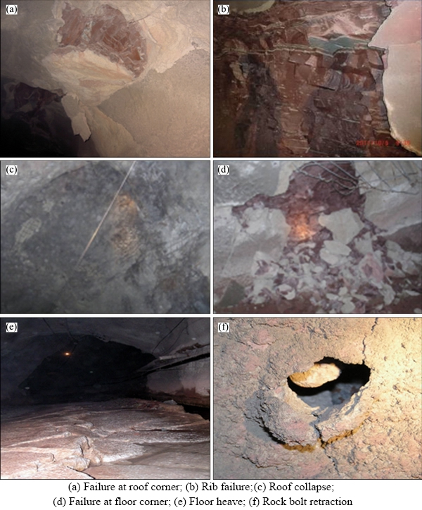
Figure 1 Failure patterns of main gateroad of Shabatu mine in red shale strata:
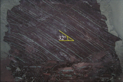
Figure 2 Bedding plane exposure at advance head of gateroad of Shabatu mine
The stress measurement in Shabatu mine was conducted in the measurement chamber of the main gateroad (location A) at 700 m deep level as shown in Figure 3. The in situ stress measurement shows that the major and intermediate principal stresses are horizontal stresses with a magnitude of 24.64 and 13.20 MPa, respectively, and the minor principal stress is vertical stress with a magnitude of 6.02 MPa. The ratio of the maximum horizontal stress to vertical stress is approximately 4.09, indicating that the mine region has a strong tectonic stress field. Figure 3 shows that the axial direction of main gateroad is not parallel with the direction of the maximum horizontal stress and hence much more severe damage occurred on the unilateral side of the developed gateroad due to stress concentration on this unilateral side after excavation [28, 29].

Figure 3 Locations of in situ stress measurement and horizontal stress distribution (Unit: m)
3 Experimental investigation
To describe the geotechnical properties of red shale and understand its mechanical behavior at mine site, geotechnical characterization of red shale was conducted in laboratory. Large red shale blocks were collected from the gateroads of Shabatu mine and transported to the laboratory for standard specimen preparation.
3.1 Microstructure analysis
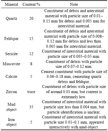
Thin section was made by grinding down a slice of red shale and its microstructure was analyzed using the petrographic microscope.Figure 4 shows the microstructure of red shale using the polarized and crossed-polarized light. It shows that the red shale has slit, clay structure and bedding features. Contents of debris and interstitial material are 45% and 55%, respectively. The main gradients of debris include sericite, quartz, muscovite, feldspar and traces of zircon, while the interstitial material includes the sericite, quartz, calcite, clay and iron minerals, belonging to the cemented rock type. The main mineral constituents of red shale are summarized in Table 1.
It can be seen that the red shale has significant microstructure characteristics with clayey minerals as the interstitial filling material. Therefore,shear-induced dislocation slip of microstructure can lead to tensile and shear failure of bedding plane as red shale strata has well-developed bedding planes as shown in Figure 1(b) and Figure 2. This can lead to complex stress and strain state of surrounding rock for underground engineering developed in red shale strata and hence exacerbate the instability of the surrounding rock.
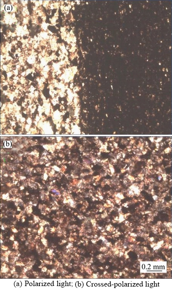
Figure 4 Microstructure of red shale:
Table 1 Main mineral constituents of red shale
3.2 Strength properties
Strength properties such as uniaxial compressive strength, tensile strength and shear strength were determined following the standard procedures suggested by International Society of Rock Mechanics (ISRM, 2007) [30].
3.2.1 UCS
The UCS of red shale specimens were measured using the Instron 1342 Servo Electric Test System. The red shale specimens prepared for UCS test are shown in Figure 5. It is known that the bedding plane has a negative effect on the UCS of rocks and impacts its stability in deep underground environment. The influence of bedding plane on the UCS of red shale was experimentally quantitated by considering different �� angles between the plane of weakness and the horizon, where two tests were conducted for each �� angle.
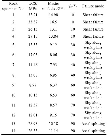
Table 2 summarizes the UCS, elastic modulus and failure modes of cylindrical red shale specimens. Note that the elastic modulus was obtained by taking the tangent modulus at 50% of the compressive strength. During the UCS tests, cylindrical red shale specimens failed in a brittle manner. As shown in Table 2, when �� falls in a range of 0�C10��, the red shale showed compressive shear failure mode. With �� increased from 30�� to 70��, the cylindrical red shale failed along the plane of weakness, indicating that the shear stress on the plane of weakness at failure is equal to, or greater than, the shear strength and leads to the slip along the plane of weakness. When the plane of weakness is parallel to the axial loading (��=90��), axial splitting occurred.
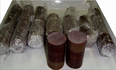
Figure 5 Red shale specimens for UCS test
Table 2 Results of UCS tests of cylindrical red shale specimens
The influence of the plane of weakness on the UCS is plotted in Figure 6 by taking the average UCS of two tests for each �� angle. It can be seen from Figure 6 that the UCS of red shale was significantly influenced by the plane of weakness. When the plane of weakness is vertical to the axial loading (��=0��), the UCS takes the maximum value, up to 34.87 MPa, and reduces to the minimum of 9.55 MPa at ��=60��. This indicates that when the angle between the plane of weakness and the horizon is smaller than a threshold of 10��, the failure plane is through the weakness plane, and when the angle between the plane of weakness and the horizon is larger than a threshold of 70��, the red shale tends to be axial splitting. However, when the angle between the plane of weakness and the horizon falls between 10�� and 70��, the weakness plane dominates in its mechanical behavior and slip along weakness plane occurs, where UCS tends to be relatively low values.
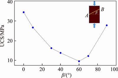
Figure 6 Influence of plane of weakness on UCS
Similarly, taking the average of elastic modulus of two tests of each ��, the influence of the weakness plane on the elastic modulus is plotted in Figure 7. The elastic modulus shows a similar U-shaped trend with UCS, as the angle �� changes. At ��=0��, the elastic modulus of red shale takes the maximum value of 15.74 GPa, tending to be behavior of intact specimen, while it takes the minimum value of 6.45 GPa at ��=60��. With the continual increase of �� angle to 90��, the elastic modulus tends to increase again.
3.2.2 Tensile strength
The tensile strengthes of diametric red shale specimens were measured by conducting the Brazilian tests with Instron 1342 Servo Electric Test System. Two kinds of tests were carried out: one is conducted with intact red shale and the other with red shale containing a single bedding plane so that the influence of weakness plane can be vividly captured. Table 3 shows that the tensile strength of red shale is significantly influenced by the weakness plane.
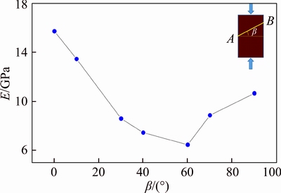
Figure 7 Influence of plane of weakness on elastic modulus
Table 3 Results of Brazilian tests of diametric red shale specimens
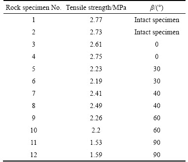
The influence of the plane of weakness on tensile strength is shown in Figure 8 by taking the average of two Brazilian tests of each �� angle. It shows that the tensile strength of red shale reduced with the angle between the weakness plane and the horizon. When the loading is parallel to the weakness plane (��=90��), the red shale has the weakest tensile capacity with a value of 1.56 MPa. However, when the plane of weakness is vertical to the loading direction (��=0��), the tensile strength is approximately equal to that of intact red shale specimen, which are 2.68 MPa and 2.77 MPa, respectively.
3.2.3 Shear strength
The shear strength is the strength of rock against shearing. The shear strength of both intact red shale and weak plane was experimentally studied by conducting direct shearing test on cubic specimens of a size of 50 mm��50 mm��50 mm under constant normal load conditions and is shown in Figure 9. For shear tests on specimens containing weak plane, the shearing direction is parallel to the weakness plane.
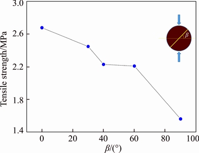
Figure 8 Influence of plane of weakness on tensile strength
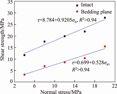
Figure 9 Shear strength of intact red shale and weakness plane under different normal stress
It shows that the shear strength of the plane of weakness of red shale tends to be considerably different from intact red shale. Assuming that both the failure of intact red shale and the plane of weakness follows the classic Mohr-Coulomb law:
 (1)
(1)
where �� is the shear strength, c is the cohesion, ��n is the normal stress and �� is angle of internal friction. Using least square method, the cohesion and angle of internal friction of intact red shale and the plane of weakness were estimated as shown in Figure 9, where the cohesion and angle of internal friction of intact red shale are approximately 8.78 MPa and 42.6��, while the cohesion and angle of internal friction of weakness plane are approximately 0.70 MPa and 27.8��.
3.3 Water-weakening properties
In Shabatu mine, the red shale is the primary water resisting stratum, however, it contains minerals sensitive to water, as shown in Table 1. In practical mining environment, the red shale in the gateroad floor has been significantly weakened due to mining-induced water inflow, resulting in severe floor heave as shown in Figure 1(e). Here, water-weakening properties of red shale were investigated to reveal its failure mechanism in present of water.
3.3.1 Water adsorption
The water adsorption capability of red shale was evaluated by immersing it into water for different times. For saturated water adsorption capability evaluation, the immersion time is extended longer enough to improve measurement accuracy.
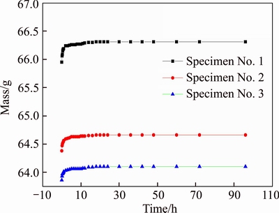
Figure 10 Mass of red shale specimen after immersing into water for different time

Figure 11 Water adsorption rate of red shale specimens with immersion time
Figure 10 shows the mass variation of red shale specimens with the immersion time and Figure 11 shows the variation of adsorption rate of red shale at different immersion time. Note that the measurement time t=0 in Figures 10 and 11 denotes the red shale in the natural state. In order to evaluate the water adsorption rate of red shale, the specimens were dried in the oven at 70 ��C for 24 h. It can be found that the mass of red shale sharply increased at the early time of water immersion, indicating strong water adsorption capability, then gradually reached a stable state, implying that the time required to be fully-statured state for investigated red shale is approximately 10 h. The water adsorption rates at the natural and saturated states are then calculated:
 (2)
(2)
 (3)
(3)
where �� is the water adsorption rate and m is the mass of red shale specimens. The subscripts o, d and s represent the natural, dried and saturated states. Therefore, the water adsorption rates at the natural and saturated states are 1.73% and 2.19%, respectively, on average.
3.3.2 Swelling
The axial and radial free swelling deformation was measured to evaluate the swelling of red shale when it is immersed in water, as shown in Figure 12. It can be seen that the axial and radial free swelling obviously increased with the immersion time, especially at the first 2 h. The swelling rate of red shale was calculated according to:
 (4)
(4)
 (5)
(5)
where V represents the swelling rate, H represents the axial dimension and D represents the radial dimension. It can be calculated that the axial free swelling rate is 0.3% and the radial free swelling rate is 0.6% after immersion of 50 h.
3.3.3 Water-degraded UCS
The water-weakened UCS of red shale was studied using the Instron 1342 Servo Electric Test System after immersing the specimens in water for different time, as shown in Figure 13. Measurement time t=0 means that the red shale specimens are in the natural state. The data show that the UCS of red shale is sharply degraded by water within 1 h, where the UCS is reduced from 22.20 to 10.33 MPa on average, approximately by 53.5%. When the immersion time is up to 24 h, the UCS of red shale is reduced by 75%. With continual immersion to 72 h, slaking occurs locally and its UCS reduces incredibly to 1.80 MPa, only approximately 8.1% of that in natural state.
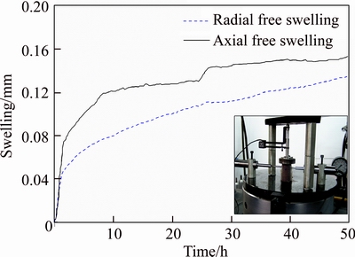
Figure 12 Axial and radial free swelling of red shale
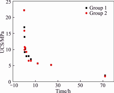
Figure 13 Water-degraded UCS of red shale at different immersion time
4 Field characterization
In underground mining, limit abutment pressure equilibrium exists from the excavation boundary to the far-field country rock, consisting of fractured damage zone, plastic zone and elastic zone. Field identification of fractured damage zone is crucial in support design. To describe the excavation-disturbed zone of the gateroad in red shale of Shabatu mine, ultra-sonic tests were conducted in field using BA-II (CT-2) rock fracture detector, as shown in Figure 14(a).
Measurement stations P1 and P2 were set up in field. The layout of borehole for sonic tests is schematically shown in Figure 14(b). At place P1, the gateroad is unsupported during the sonic tests, while at place P2, the gateroad is supported with existing plan, where combined bolt-mesh-shotcrete support is used as shown in Figure 15. The rock bolt is 32 mm in diameter and 2.5 m in length. The thickness of sprayed concrete is 120 mm.

Figure 14 Excavation disturbed zone detection:
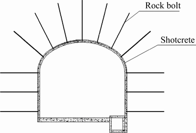
Figure 15 Schematic diagram of existing support
Figure 16 shows the development of fractured damage range at different gateroad locations after excavation. After three days of excavation, the fractured damage length along vertical direction of roof was 89 cm and 99 cm for unsupported and supported cases, respectively. This amount of deformation produced shortly after excavation, namely transient deformation here. Three months later, the cumulative fractured damage length along vertical direction of roof increased to 123 cm and 142 cm for unsupported and supported cases. Therefore, the transient deformation is approximately 72.4% and 69.7% of the cumulative deformation of three months. Comparing Figures 16(a) with (b), it can be seen that, with the existing support, the fractured damage range of surrounding rock only reduced by approximately 16% on average. Considering the severe deformation illustrated in Figure 1, the existing support plan should be optimized for ground control.

Figure 16 Development of fractured damage range of gateroad after excavation:
5 Indications to ground control
The red shale contains clayey minerals on the micro scale and tends to be vulnerable to the water. After water adsorption, the strength of red shale is significantly degraded and bulk swelling occurs. This produces a negative effect on the stability of gateroad situating in red shale strata. Taking the floor heave shown in Figure 1(e) as the example, the water-weakening properties of red shale result in the low load bearing capacity of gateroad floor, especially for fully-saturated state. Bulking swelling due to water adsorption puts the surrounding rock in a squeezing state and tends to deform towards the gateroad boundary. However, there is no reinforcement in the floor with the existing support plan. Thereby, the red shale in floor swells and becomes the main profile section of stress release, inducing the severe floor heave. Additionally, the high horizontal stresses are another contributor to the large deformation in floor and roof section of gateroad. Considering the water-weakening characteristics of red shale illustrated by laboratory tests, it is recommended that the water inflow within several hours of excavation must be strictly controlled. This is important for the gateroad stability developed in red shale stratum. Otherwise, the strength of red shale can be significantly reduced. In underground mining, concrete reinforcement is recommended in floor to isolate water together with rock bolting to prevent excessive floor deformation.
Macroscopically, the red shale is layered geologically, which significantly influences its mechanical properties. Figure 16 shows that the profile of fractured damage zone of gateroad in layered red shale stratum of Shabatu mine tends to be asymmetrical. The deformation in the right roof corner is larger than that of left roof corner, while the deformation in the right floor corner is smaller than that of left floor corner. Also, the deformation in the left wall is larger than that of right wall. These deformation characteristics are not only related with the bedding plane, but also related with the actual layout of the gateroad. As stated previously, the axial direction of main gateroad is not parallel with the direction of the maximum horizontal stress and hence much more severe damage occurs on the unilateral side of the developed gateroad due to stress concentration after excavation [29]. This is consistent with the detected geometrical profile of fractured damage zone of gateroad.
In field, the fractured damage zone in short time is approximately 70% of the cumulative fractured damage zone in long term. Considering its sensible property with water, the red shale can be categorized as the engineering soft rock. For better ground control at Shabatu mine, in-time support should be conducted and the energy adsorbing rock bolt, which consists of a certain of deformed sections to adsorb energy as the red shale deforms shortly after excavation, is recommended to ensure the rock bolt still an effective support after large deformation. Furthermore, it is recommended that the designed gateroad should reserve a certain deformation so that it can meet the production requirement after deformation. Also, once spalling occurs in reinforced gateroad skin, the repair should be conducted as earlier as possible in case of continual deterioration by water. However, the rock bolt length can still be 2.5 m as the fractured damage zone of gateroad excavation is less than 1.5 m, as shown in Figure 16.
6 Conclusions
Geotechnical characterization of red shale appeared in deep underground mining is conducted by carrying out laboratory and field investigation.
1) On the micro scale, the red shale contains clayey minerals filling the interstitial structure. This can lead to low shear strength of microstructure and make it vulnerable to water as well. The strength properties including UCS, tensile strength and shear strength, were experimentally investigated.
2) A U-shaped curve of UCS exists with the increase of the angle between the weakness plane and the horizon, and its failure mode varies with this angle during UCS tests as well. However, its tensile strength is reduced with this angle monotonically measured by Brazilian test. The shear strength of weakness plane of red shale tends to be considerably lower than that of intact red shale, especially the cohesion strength component if Mohr-Coulomb failure criterion is assumed.
3) The water adsorption rate under the saturated states is 2.19%. While immersed in water for 72 h, its UCS reduces to approximately 8.1% of that of red shale in the natural state.
4) With field sonic tests, an asymmetrical geometrical profile of fractured damaged zone of developed gateroad is identified, resulting from geological bedding planes and detailed gateroad layout with regards to in situ stress field. The main indications of this study are that the red shale is in a category of engineering soft rock.
5) For ground control in red shale stratum, water inflow within several hours of excavation must be strictly controlled and prevented. Energy adsorbing rock bolt should be installed to ensure that the rock bolt can still be an effective support after large deformation, and the floor reinforcement should be addressed to eliminate floor heave.
References
[1] LI X B, WENG L. Numerical investigation on fracturing behaviors of deep-buried opening under dynamic disturbance [J]. Tunn Undergr Space Technol, 2016, 54(4): 61�C72.
[2] LI X B, LI C J, CAO W Z, TAO M. Dynamic stress concentration and energy evolution of deep-buried tunnels under blasting loads [J]. Int J Rock Mech Min Sci, 2018, 104(4): 131�C146.
[3] LI X B, WANG S F, WANG S Y. Experimental investigation of the influence of confining stress on hard rock fragmentation using a conical pick [J]. Rock Mech Rock Eng, 2018, 51(1): 255�C277.
[4] HE M. Latest progress of soft rock mechanics and engineering in China [J]. Rock Mech and Geotech Eng, 2014, 6(4): 165�C179.
[5] KANJI M A. Critical issues in soft rocks [J]. Rock Mech Geotech Eng, 2014, 6(3): 186�C195.
[6] JOHNSTON I W. Geomechanics and the emergence of soft rock technology [J]. Aust Geomech, 1991, 21(12): 3�C26.
[7] BROWN E T. Rock characterization testing and monitoring, ISRM suggested methods [M]. Pergamon, Oxford, 1981.
[8] YANG X L, ZHANG J H, JIN Q Y, MA J Q. Analytical solution to rock pressure acting on three shallow tunnels subjected to unsymmetrical loads [J]. Journal of Central South University, 2013, 20(2): 528�C535.
[9] HE Xian-qun, XU Chao-shui, PENG Kang, HUAN Gun. Simultaneous identification of rock strength and fracture properties via scratch test [J]. Rock Mech Rock Eng, 2017, 50(8): 2227�C223.
[10] HE M, JING H, SUN X. Soft rock engineering mechanics [M]. Beijing: Science Press, 2002. (in Chinese)
[11] CIANTIA M O, CASTELLANZA R, CROSTA G B, HUECKEL T. Effects of mineral suspension and dissolution on strength and compressibility of soft carbonate rocks [J]. Eng Geol, 2015, 184: 1�C18.
[12] LI X, WANG S, WANG S. Experimental Investigation of the influence of confining stress on hard rock fragmentation using a conical pick [J]. Rock Mechanics & Rock Engineering, 2018, 51(1): 255�C277.
[13] YOSHINAKA R, TRAN T V, OSADA M. Mechanical behavior of soft rocks under triaxial cyclic loading conditions [J]. Inter J Rock Mech Min Sci, 1997, 34(3, 4): 3�C4.
[14] COVIELLO A, LAGIOIA R, NOVA R. On the measurement of the tensile strength of soft rocks [J]. Rock Mech Rock Eng, 2005, 38(4): 251�C273.
[15] ULUSAY R, ERGULER Z A. Needle penetration test: Evaluation of its performance and possible uses in predicting strength of weak and soft rocks [J]. Eng Geol, 2012, 149(2): 47�C56.
[16] PENG Kang, LI Xi-bing, WANG Ze-wei. A numerical simulation of seepage structure surface and its feasibility verifying [J]. Journal of Central South University, 2013, 20(5): 1326�C1331.
[17] AYDAN  , SATO A, YAGI M. The inference of geo-mechanical properties of soft rocks and their degradation from needle penetration tests [J]. Rock Mech and Rock Eng, 2014, 47(5): 1867�C1890.
[18] CORTHSY R, LEITE M H, GILL D E, GAUDIN B. Stress measurements in soft rocks [J]. Eng Geol, 2003, 69(3, 4): 381�C397.
[19] TAHERI A, TANI K. Characterization of a sedimentary soft rock by a small in-situ triaxial test [J]. Geotech Geol Eng, 2010, 28(3): 241�C249.
[20] CHANG Q, ZHOU H, XIE Z, SHEN S. Anchoring mechanism and application of hydraulic expansion bolts used in soft rock roadway floor heave control [J]. Inter J Min Sci Tech, 2013, 23(3): 323�C328.
[21] SHEN B. Coal mine roadway stability in soft rock: A case study [J]. Rock Mech Rock Eng, 2013, 47(6): 2225�C2238.
[22] KANG H P, LIN J, FAN M J. Investigation on support pattern of a coal mine roadway within soft rocks��A case study [J]. Coal Geol, 2015, 140(2): 31�C40.
[23] ZHOU H, ZHANG C, LI Z, HU D, HOU J. Analysis of mechanical behavior of soft rocks and stability control in deep tunnels [J]. Rock Mech Geotech Eng, 2014, 6(3): 219�C226.
[24] DONG L J, SHU W W, LI X B, ZHANG J M. Quantitative evaluation and case studies of cleaner mining with multiple indexes considering uncertainty factors for phosphorus mines [J]. J Clean Prod, 2018, 183(3): 319�C334.
[25] LI X B, DU J, GAO L, HE S Y, GAN L, SUN C, SHI Y. Immobilization of phosphogypsum for cemented paste backfill and its environmental effect [J]. J Clean Prod, 2017, 156(7): 137�C146.
[26] DONG L J, ZOU W, LI X B, SHU W W, WANG Z W. Collaborative localization method using analytical and iterative solutions for microseismic/acoustic emission sources in the rockmass structure for underground mining [J]. Eng Fract Mech, 2018, 5(2):1�C18. DOI: https://doi.org/ 10.1016/ j.engfracmech. 2018.01.032.
[27] DONG L J, SUN D Y, LI X B, DU K. Theoretical and experimental studies of localization methodology for AE and microseismic sources without pre-measured wave velocity in mines [J]. IEEE Access, 2017, 5(9): 16818�C16828.
[28] HE Xian-qun, XU Chao-shui, PENG Kang, HUAN Gun. Simultaneous identification of rock strength and fracture properties via scratch test [J]. Rock Mechanics and Rock Engineering, 2017, 50(8): 2227�C2234.
[29] MA Nian-jie, HOU Chao-jiong. Mining pressure theory and application of mining roadway [M]. Beijing, China: China Coal Industry Publishing House, 1995. (in Chinese)
[30] ULUSAY R, HUDSON J A. The complete ISRM suggested methods for rock characterization, testing and monitoring: ISRM Turkish national group, Ankara, Turkey [J]. Bull Eng Geol Environ, 2009, 68: 287�C288.
(Edited by FANG Jing-hua)
���ĵ���
���ҳ�ҵ������Լ�����������ѹ���Ƽ���
ժҪ��������һ�ֶԵ��ʹ�����Σ�������塣������Ҫ�о��������ʱ��ҳ�ҵ�ʵ������ʵ��Ӧ���еĵ������ԡ�ͨ���ɷַ��������ṹ��ǿ�����ԵȲ��ԣ�������ˮ����ʵ�飬��ʾ��ԭ��Ӧ�������л��Ŷ����ض�����к�ҳ�ҵ�ʧ�Ȼ�����ʵ������������ҳ����ʧ��ʱ���������ԣ�����ǿ�ȱ�ͣ���ˮ��������ʧȥճ��������Ϊ������ʵ����ԡ�������������ˮƽ�ߵļнDz��������ڵ��Όѹǿ��ͼ���Ͽ����Լ��������߳�U�ͣ���ҳ�ҵ�ʧ��ģʽ��������кܴ�Ĺ�����ǿ��ʵ���к�ҳ�ҵĿ���ǿ��������Ƕȵ������������С������ǿ��Ҳ��������ҳ�ҵĵ͡���ʹ��Ħ������ǿ������ʱ���ھ���Ҳ��������Ƕȵ��������С����ҳ���ڽ�ˮ72 h���Όѹǿ�ȱ�ԭʼ״̬�ļ���91.9%��ͨ���ֳ�������ʵ�飬���ڲ�����Ĵ��ڣ����������Ӧ��������ʱ��۲쵽һ�����ԵIJ��Գƶ����档�����о���ʵ��������ҳ��Ϊ�������ң�������ɵ�ѹ���ƻ���ͬ���������Ӧ�ϸ����ˮ�������ڱ��νϴ�������ʹ��ԤӦ��ê�ˡ�
�ؼ��ʣ���ҳ�ң����ң�����ɣ��������ԣ���ѹ���ƣ�ˮ����
Foundation item: Projects(51774058, 51674047) supported by the National Natural Science Foundation of China; Projects(cstc2016jcyjA1861, cstc2018jcyjA3320) supported by Chongqing Basic Science and Cutting-edge Technology Special Projects, China; Project(2015M570607) supported by Postdoctoral Science Foundation of China
Received date: 2017-09-30; Accepted date: 2018-03-13
Corresponding author: PENG Kang, PhD, Associate Professor; Tel: +86-15974269965; E-mail: pengkang@cqu.edu.cn; ORCID: 0000- 0002-1405-3272
Abstract: Geotechnical properties of red shale encountered in deep underground mining were characterized on both laboratory and field scale to reveal its unfavorably in geoenvironment. Its constituents, microstructure, strength properties and water-weakening properties were investigated. In situ stress environment and mining-induced fractured damage zone after excavation were studied to reveal the instability mechanism. The results show that red shale contains swelling and loose clayey minerals as interstitial filling material, producing low shear strength of microstructure and making it vulnerable to water. Macroscopically, a U-shaped curve of uniaxial compressive strength (UCS) exists with the increase of the angle between macro weakness plane and the horizon. However, its tensile strength reduced monotonically with this angle. While immersed in water for 72 h, its UCS reduced by 91.9% comparing to the natural state. Field sonic tests reveal that an asymmetrical geometrical profile of fractured damage zone of gateroad was identified due to geological bedding plane and detailed gateroad layout with regards to the direction of major principle stress. Therefore, red shale is a kind of engineering soft rock. For ground control in underground mining or similar applications, water inflow within several hours of excavation must strictly be prevented and energy adsorbing rock bolt is recommended, especially in large deformation part of gateroad.
