

![]()

Trans. Nonferrous Met. Soc. China 22(2012) 2241-2247
Numerical simulation of optimum mining design for high stress hard-rock deposit based on inducing fracturing mechanism
YAO Jin-rui1, 2, MA Chun-de1, LI Xi-bing1, YANG Jin-lin1
1. School of Resources and Safety Engineering, Central South University, Changsha 410083, China;
2. Guizhou Kaiyang Phosphate Mine Group Co., Guiyang 550302, China
Received 20 November 2011; accepted 25 July 2012
Abstract:
The 3D numerical simulation model of deep hard-rock deposit in Kaiyang Phosphate Mine of Guiyang was established based on the practical engineering using 3DEC numerical simulation software. The distribution characteristics of displacement fields and plastic zones of the orebody were simulated in three different excavation cases, including the case of excavation artificial inducted roadway in the orebody, the case of horizontal or vertical excavation direction and the case of the upward or downward excavation order. The simulation results indicate that the plastic zone and displacement field of surrounding rock around the inducted roadway are continuously increasing with the increase of the exposure time after digging an artificial inducted roadway in the orebody. Thus the raw rock ore becomes easier to be fragmented, which provides advantageous conditions for roadheader to cut high stress hard-rock. It is worthy noting that there is a large difference in effective utilization of deep ground pressure between horizontal and vertical excavation directions. The later can produce larger deformation and fracture zone than the former on the rock mass around the deduced roadway, which means that the later may utilize the high ground pressure more effectively to break hard-rock. And the obtained results also show that upward excavation order is more helpful for ground pressure to break rock than downward excavation order.
Key words:
inducted fracturing; high stress hard-rock deposit; excavation case; roadheader excavation; numerical simulation;
1 Introduction
In deep mining practice, the traditional drilling and blasting method predominantly used in hard-rock mining has been exposed its defects increasingly [1,2], including dangerous operation process, low production efficiency, low energy efficiency, and large derivative damages to nearby roadway. Meanwhile, the blasting is also an important factor in inducing rock burst [3-6]. Several mining industry developed countries have started some research projects [7-10] to study the non-blasting mining methods in hard-rock mines since the end of the 20 century. Their main purpose is to find a new efficient method to break rock instead of using tradition blasting method. In recent decades, the mechanical rock breaking becomes the most typical non-blasting mining method, such as tunnel boring machine and roadheader, which was firstly used in soft rock mines, and its suitable compressive strength range is from 10 MPa to 70 MPa. But when it was used in hard-rock mines, its actual application effect was restricted greatly. In recent years, a few new tunnel boring machines have appeared in the world which can cut some hard-rocks with 100-300 MPa compressive strength, but they are generally used in drifting roadways or secondary rock breaking, not in large-scale mining, as they crack and break rock ore only by external power considering high stiffness and abradability of hard-rock. In addition, as to large-scale mining, the price and working cost of machines are also too expensive.
Some scholars realize that high stress hard-rock is actually an energy storage body, inspired by the phenomena of blasting inducing rock burst and drilling and blasting easily in deep mining [11-14]. The gravity and tectonic stress make it store high elastic strain energy inside, where a tendency to break rock easily exists. Therefore, its internal stored energy could turn to useful power to break itself if an appropriate inducing fracturing method is formed, then high-efficiency continuous mining may become a reality in no or little explosive condition, which is called non-blasting continuous mining in high stress hard-rock [15].
Kaiyang Phosphate Mine of Guiyang is the largest underground phosphate mine in China, and its mining depth reaches about 800 m underground, where the deep ground pressure is very high. There are two roadheaders (type: EBJ160TY and EBZ230, and the strength is less than 80 MPa) used in drifting roadway in soft rock originally. However, the average compressive strength is over 120 MPa, which greatly exceeds their application of the strength range. Some early cutting phosphate ore tests with roadheaders showed that they can hardly break such rock ore, and the cutting teeth are abraded rapidly and the working face is full of dust. This indicates that the cutting ability of these roadheaders cannot satisfy the requirement of directly mining and the only way for roadheader to cut deep hard-rock is to reasonably utilize deep ground pressure to break rock ore first. To find the most reasonable way of using ground pressure to break rock ore and realize non-blasting continuous mining in high stress hard-rock, the inducing fracturing engineering and some different mining cases are calculated using numerical simulation method based on the real geological and mechanical conditions of the deposit in Kaiyang Phosphate Mine.
2 Calculation model and parameter selection
2.1 Calculation model
There are four kinds of ore-rocks in Kaiyang Phosphate Mine from top to bottom, including dolomite, phosphate, sandstone and red shale. The dip angle of deep phosphate deposit is nearly 35�㣬and its real thickness is 6-7 m, as shown in Fig. 1.
The displacement fields and plastic zone distribution rules of several different mining cases were calculated using the 3DEC. The calculation region is selected as 200 m �� 200 m �� 200 m. Model boundary displacement is fixed all around and at the bottom, while on the top boundary stress is loaded. The model is located at 640 m level, and its stratum thickness is about 700 m in z direction. The numerical simulation model of deep deposit is shown in Fig. 2.
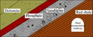
Fig. 1 Distribution characteristics of deep ore-rocks

Fig. 2 Numerical simulation model of deep deposit
In this simulation process, the rock mass was taken as elasto-plastic model of which yield criterion is Mohr-Coulomb strength theory, while for the bedding elastic model, coulomb sliding theory is the most appropriate yield criterion.
2.2 Physico-mechanical parameters of ore-rocks
The physico-mechanical parameters of four types of ore-rocks in Kaiyang Phosphate Mine were obtained from engineering geological survey reports and laboratory rock mechanics tests, as listed in Table 1.
In the discrete element method calculation program, the relationships among the shear modulus (G), volume modulus (K), Poisson ratio (��) and elastic modulus (E) were described as follows:
![]() (1)
(1)
![]() (2)
(2)
For joints, normal stiffness and shear stiffness are calculated by the following formula:
![]() (3)
(3)
![]() (4)
(4)
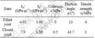
where kn and ks are respectively normal stiffness and shear stiffness; Em and Er are respectively elastic modulus of the continuum and rock; Gm and Gr are respectively shear modulus of the continuum and rock; s is the mean spacing of joints. Considering that joint strength would be weakened by joints filling, normal stiffness and shear stiffness are gained when joints are filled or closed. The mechanical parameters of joints are listed in Table 2.
Table 1 Physico-mechanical parameters of ore-rocks

Table 2 Mechanical parameters of joints
2.3 In-situ stress boundary condition
According to ground stress survey report in Kaiyang Phosphate Mine, the in-situ stress was measured in the whole mine area. Based on the results, laws of in-situ stress and buried depth can be gained by using linear regression method, and their regression equations are expressed as follows:
 (5)
(5)
where ��hmax, ��hmin and ��z are respectively the maximum principal stress, the minimum horizontal stress and vertical principal stress, and H is buried depth.
With these practical ground stress boundary conditions and rock mechanics parameters, the calculation model can be established.
3 Numerical simulation and result analysis
3.1 Simulation analysis on excavation inducted roadway in orebody
Because the roadheader was incapable of cutting the primary orebody directly and efficiently, a slightly inclined roadway was excavated in the orebody using drilling and blasting method firstly. This roadway not only can provide operational room for roadheader, but also can make the orebody near the free face crack and thus be cut easily due to the high stress concentration coming from deep ground pressure. Considering such factors as flexibility and climbing ability of cantilevered roadheader, the gradient of the inclined roadway is 10�� and its sizes are 6 m��3 m��100 m.
Using the established model, according to calculation and analysis of the stress, the displacement and plastic zone in the orebody after excavation, the variation of the plastic zone and the displacement around the roadway with the exposure time were obtained, where the step size represented the exposure time after excavation.
As can be seen from Fig. 3, the deep inducing fracturing roadway has a wide displacement distribution during excavation. It is noticeable that the more away from the center of the roadway, the smaller the displacement of the surrounding rock. At the moment of excavation, the displacement mainly appeared in the left side of the roadway. The distribution of the upper left corner is wide while the right corner is small. With the extension of exposure time after excavation, the displacement of surrounding rock will adjust with the stress adjustment. The location of the maximum displacement moves from the left side to the roof constantly, and the distribution gradually becomes smaller. When reaching to the 900th step, the displacement around the roadway is basically stable. The maximum displacement mainly concentrates in the roof of the roadway. The failure appears at the joint area of the dolomite and phosphate rock.
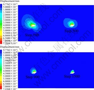
Fig. 3 Displacement field of inducted fracturing roadway vs exposure time
While excavation started, the surrounding rock was in the shearing state and the plastic zone increased along with the step, spreading perpendicularly to the roadway. Conversely, the plastic zones in the two sides were relatively small, basically unchanged. When the steps reached 900, the destruction area maintained generally stable. The plastic flow destruction occurred as local rocks were subject to the joint effects of tension and shear stress (see Fig. 4). In Fig.4, shear(p) represents a zone of the surrounding rock was in a plastic state previously because of shere; shear(n) represents a zone of the surrounding rock is in a plastic state now because of shere; tension(p) represents a zone of the surrounding rock was in a plastic state previously because of tension; tension(n) represents a zone of the surrounding rock is in a plastic state previously now because of tension.To sum up, the high stress orebody in the two sides of the roadway collapsed with the increase of exposure time as a result of the excavation of a gently inclined roadway, which was conducive to cutting the ores easily. However, this would severely undermine the roof and the floor, which implied that immediate support should be taken.

Fig. 4 Plastic zone of inducted fracturing roadway vs exposure time: (a) Step 100; (b) Step 500; (c) Step 900; (d) Step 1500
3.2 Simulation analysis in different excavation directions
Based on the structure and construction characteristics of the roadheader, it should take forward drifting method. Seen from section of orebody, there are horizontal and vertical directions for extraction way to be chosen, as shown in Fig. 5.
The numerical model loaded with practical ground stress on the boundary was calculated and analyzed to compare the effects of breaking ore-rock in two extraction directions. Figure 6 shows displacement field of surrounding ore-rock near free face in different excavation directions. It is noticed that the distribution characteristic of displacement field is totally different in different excavation directions even if the size of section is the same. When excavated vertically, the deformations on two sides of roadway are very obvious, especially on the middle part of the left side. But when excavated horizontally, the deformation is concentrated on the roof, mainly at the top left corner and the influence area is smaller than another case. This indicates that when selecting mining methods, vertical excavation should be better than horizontal excavation by using ground pressure effectively.

Fig. 5 Sketch in different extraction directions: (a) Vertical excavation; (b) Horizontal excavation

Fig. 6 Displacement field in two excavation directions
Figure 7 shows the plastic zone distribution of surrounding ore-rock near free face in different excavation directions. When excavated in different directions, the plastic zone is eventually different. When excavated vertically, the plastic zone is larger obviously than that in horizontal excavation and its surrounding ore-rock at two sides of roadway moves to free face potentially, which is significant to break ore-rock by using high ground pressure in Kaiyang Phosphate Mine.

Fig. 7 Plastic zone distribution in two excavation directions: (a) Vertical excavation; (b) Horizontal excavation
3.3 Simulation analysis of different excavation orders
The above results of numerical simulation show that high ground stress will be sufficiently used when taking vertical excavation direction. Therefore, this method should be adopted in the next mining process. Restricted by roadheader��s effective excavation section, the whole section of vertical roadway cannot be excavated at only one time and has to do it by two steps. Thus, it exists a problem of excavation order. In order to study the effects of different excavation orders in the direction of vertical excavation on using deep ground pressure reasonably, two cases are set in the same excavation direction and different excavation orders which divide into first-up-then-down and first-down-then-up, as shown in Fig. 8. Section sizes of roadways �� and �� are both 4 m��4 m.
The distribution characteristics of displacement and plastic zone in surrounding rock ore of roadway excavated in two orders by numerical simulation results are shown in Figs. 9 and 10.
From Fig. 9, two kinds of excavation orders were analyzed. In the case I, the displacement distribution range is larger after excavating roadway �� firstly but those values are smaller and in the scope of 5-7 mm. In the case II, displacement concentration occurs in lower right corner of roadway after excavating roadway �� firstly and those values are in the scope of 7-12 mm. Displacement on the left side of roadway is almost the same, but displacement on the right side in the case I is concentrated at the lower position while in the case II is at the upper position where values are one order of magnitude bigger than those in the case I. In summary, the case II is beneficial to use ground pressure to extract ore.

Fig. 8 Sketch of vertical extraction in different excavation orders: (a) Case I, first �� then ��; (b) Case II, first �� then ��

Fig. 9 Displacement of roadway in different excavation orders: (a),(a��) Case I; (b),(b��) Case II

Fig. 10 Plastic zone of roadway in different excavation orders: (a),(a��) Case I; (b),(b��) Case II
Figure 10 also shows that surrounding rock ores in cases I and II are both under shear force in Step 1, which causes failure partly but cracks do not run through. When in Step 2, surrounding rock ore in the case I is still damaged by shear force, but in the case II it is damaged by shear and tensile forces. However, the rock mass tends to fracture under tensile force. In conclusion, upward excavation order in the case II is better.
4 Conclusions
1) Excavating a slightly inclined inducted roadway in the orebody before using roadheader cutting raw ore directly is a useful way to make use of deep ground pressure to fracture hard-rock. The results of numerical simulation show that deformation and damage zone of the inclined inducted roadway will both extend with the increase of exposure time, which will make the hard-rock ore easy to be cut.
2) The obtained results from numerical simulations show that there are great differences in different excavation directions and excavation orders on sufficiently using deep ground pressure to break rock ore. The vertical excavation direction and upward excavation order can get better effects than horizontal excavation direction and downward excavation order.
3) The results from the presented investigation may be benefit to the design of non-explosive continuous mining method, efficiently using ground pressure breaking rock, and reasonable excavation cases in high stress conditions in deep mines.
References
[1] DONG Long-jun, LI Xi-bing, LI Ping-ping. Crucial understanding and decision-making technology for deep mining [J]. Nonferrous Metal, 2009, 61(1): 116-120. (in Chinese)
[2] LI X B, DONG L J. Comparison of two methods in acoustic emission source location using four sensors without measuring sonic speed [J]. Sensor Letters, 2011, 9(5): 2025-2029.
[3] XU Ze-min, HUANG Run-qiu. Relationship between rock burst and blasting [J]. Chinese Journal of Rock Mechanics and Engineering, 2003, 22(3): 414-419. (in Chinese)
[4] XIE Yong-mou, LI Tian-bin. Primary discussion on blast��s affection on rockburst [J]. The Chinese Journal of Geological Hazard and Control, 2004, 15(1): 61-64. (in Chinese)
[5] ZHANG Li-ming, WANG Zai-quan, HE Jun-zheng. Analysis of failure characteristics of rock under unloading conditions and their effects on rock burst [J]. Journal of Xi��an University of Architecture & Technology: Natural Science Edition, 2007, 39(1): 110-113. (in Chinese)
[6] JIANG Yao-dong, ZHAO Yi-xin, SONG Yan-qi, LIU Wen-gang, ZHU Dao-jian. Analysis of blasting tremor impact on roadway stability in coal mining [J]. Chinese Journal of Rock Mechanics and Engineering, 2005,24(17):3131-3136.
[7] WANG He-xiang. Research progress of no-blasting mining technology of underground hard rock [J]. Xinjiang Youse Jinshu, 1996(4): 13-16 .(in Chinese)
[8] WILKE FL, SPACHTHOLZ FX. Operational conditions for continuous mining systems in hard rock open pit mines [EB/OL]. Brite EuRam II project BE 6044 of the European Commission. www.tu-berlin.de, 1993.
[9] SINGHS P. Non-explosive applications of the PCF concept for underground excavation[J]. Tunnelling and Underground Space Techn, 1998, 13(3): 305-311.
[10] PICKERING R, YOUNG C, DIMILLO T. The innovative application of tunnel digging machines and non-explosive rock breaking to high speed development [C]//The 6th International Symposium on Mine Mechanization and Automation. Johannesburg: South African Institute of Mining and Metallurgy, 2001: 49-54.
[11] ZHU Qi-hu, LU Wen-bo, SUN Jin-shan. Discussion on mechanism of rockburst and stress state based on energy principles [J]. Engineering Journal of Wuhan University, 2007, 40(2): 84-87. (in Chinese)
[12] XU Ze-min, WU Pei-guan, WANG Su-da, TANG Zheng-guang. Analysis of energy released in process of rock-burst [J]. Journal of Natural Disasters, 2003, 12(3): 104-110. (in Chinese)
[13] CAI Mei-feng, WANG Jin-an, WANG Shuang-hong. Analysis on energy distribution and prediction of rock burst during deep mining excavation in Linglong Gold mine [J]. Chinese Journal of Rock Mechanics and Engineering, 2001, 20(1): 38-42. (in Chinese)
[14] XIE He-ping, JU Yang, LI Li-yun. Criteria for strength and structural failure of rocks based on energy dissipation and energy release principles [J]. Chinese Journal of Rock Mechanics and Engineering, 2005, 24(17): 3003-3010. (in Chinese)
[15] LI Xi-bing, GU De-sheng. The hazard control and cataclastic mutagenesis induced by high stress in hard rock mining at depth [C]//The 175th Xiangshan Science Congress. Beijing: China Environmental Science Press, 2002: 101-108. (in Chinese)
���ڵ�ѹ�յ����ѵĸ�Ӧ��Ӳ�ҿ��Ż��ز���ֵģ��
Ҧ����1, 2��������1����Ϧ��1�������1
1. ���ϴ�ѧ ��Դ�밲ȫ����ѧԺ����ɳ 410083��
2. ���ݿ����ţ����� 550302
ժ Ҫ��������ɢԪ��ֵģ���������3Dec�����ݹ����������Ӳ�ҿĹ���ʵ�����������ά��ֵģ��ģ�ͣ��Կ������Ӳ�ҿ�3�ֲ�ͬ���ڹ�������ģ����㣬�����ڿ����п��ڵ�ѹ�յ������������ͬ����(ˮƽ�������)����ͬ˳��(���Ϻ���/���º���)���ں�����Χ�����λ�ƺ��������ֲ����������������ڿ����п����յ��������ʱ������ܱ�������������λ�Ƴ����ű�¶ʱ����ӳ������������ҳ�����������������Ʒ�չ����Ϊ������ĸ�Ч�и�ز��ṩ��������������ͬ���ڷ���Գ���������ѹЧ����ͬ�������ڱ�ˮƽ�����ڿ��γɸ����λ�Ƴ��������ƻ�������ѹ���ѵ�Ч�������ԣ����º���ʽ���ڱ����Ϻ���ʽ���ڲ������ٿ��渽�����Ҳ�������ı��������ƻ�����������Ч���������Ӧ�����ҡ����о��Կ��������Ӧ��Ӳ�ҿ���DZ�������������ɵIJɿ���ơ�������õ�ѹ���Һͺ���ȷ�����ڷ�ʽ������Ҫ�����塣
�ؼ��ʣ���ѹ�յ����ѣ���Ӧ��Ӳ�ҿ����ڹ�����������زɣ���ֵģ��
(Edited by LI Xiang-qun)
Foundation item: Projects (50934006, 10872218) supported by the National Natural Science Foundation of China; Project (2010CB732004) supported by the National Basic Research Program of China
Corresponding author: MA Chun-de; Tel: +86-13319515799; E-mail: cdma@mail.csu.edu.cn.
DOI: 10.1016/S1003-6326(11)61455-6
Abstract: The 3D numerical simulation model of deep hard-rock deposit in Kaiyang Phosphate Mine of Guiyang was established based on the practical engineering using 3DEC numerical simulation software. The distribution characteristics of displacement fields and plastic zones of the orebody were simulated in three different excavation cases, including the case of excavation artificial inducted roadway in the orebody, the case of horizontal or vertical excavation direction and the case of the upward or downward excavation order. The simulation results indicate that the plastic zone and displacement field of surrounding rock around the inducted roadway are continuously increasing with the increase of the exposure time after digging an artificial inducted roadway in the orebody. Thus the raw rock ore becomes easier to be fragmented, which provides advantageous conditions for roadheader to cut high stress hard-rock. It is worthy noting that there is a large difference in effective utilization of deep ground pressure between horizontal and vertical excavation directions. The later can produce larger deformation and fracture zone than the former on the rock mass around the deduced roadway, which means that the later may utilize the high ground pressure more effectively to break hard-rock. And the obtained results also show that upward excavation order is more helpful for ground pressure to break rock than downward excavation order.
