
J. Cent. South Univ. Technol. (2011) 18: 1133-1138
DOI: 10.1007/s11771-011-0814-3![]()
Static characteristics of new type externally pressurized spherical air bearings
WANG Fu-sheng(������), BAO Gang(����)
School of Mechanical and Electrical Engineering, Harbin Institute of Technology, Harbin 150001, China
? Central South University Press and Springer-Verlag Berlin Heidelberg 2011
Abstract:
In order to provide some theoretical guideline for the structure design of the new type externally pressurized spherical air bearings, the static characteristics and the factors affecting the static characteristics of the air bearings were analyzed. A finite volume method was adopted to discretize the three-dimensional steady-state compressible Navier-Stokes equations, and a modified SIMPLE algorithm for compressible fluid was applied to solve the discretized governing equations. The pressure field and velocity field of the air bearings were obtained, and the factors and rules affecting the static characteristics were analyzed. The results show that the pressure of near air intakes can reach above 80% of air supply pressure, and there is a pressure steep fall around the air intakes. When the film thickness is greater than 20 ��m, the bearing capacity rapidly decreases as film thickness increases. As the air supply pressure increases from 0.2 to 0.6 MPa, the maximum static stiffness increases by more than three times. The calculation method proposed well fits the general principle, which can be extended to the characteristic analysis of other air bearings.
Key words:
static characteristics; spherical air bearings; air film; finite volume method��
1 Introduction
Air bearings can offer a nearly torque-free environment, perhaps as close as possible to that of space, and for this reason it is the preferred technology for accurate mass properties measurement [1] and ground- based research in spacecraft dynamics and control [2-3]. Compared with the early adopted orifice compensated air bearings, externally pressurized spherical air bearings with inherent compensation have some advantages, such as simple structure and easy processing. In addition, they are able to ensure the stability in the large scale of pressure [4]. As a result, externally pressurized spherical air bearings have been widely used in mass properties measuring instruments and air bearing tables for satellite control system simulation in recent years [5-6].
Mass properties measuring instruments are particularly recommended for determining mass properties of rockets, satellite and ballistic objects. The instruments have high accuracy over a wide range of test object weight and moment of inertia. This permits the measurement of moment of inertia about an axis which does not pass through the center of mass of the test object. Externally pressurized spherical air bearing is the key component of the mass properties measuring instruments. WILLIS performed the first investigation of externally pressurized air lubricating films as part of an experimental study of radial air flow between parallel surfaces. CROSSMAN [7] studied the application of flow and stability theory to the design of externally pressurized spherical gas bearings. GUO et al [4] and REN et al [8] studied the static characteristics of conventional spherical gas bearings using finite element method and finite volume method, respectively.
This research is emphasized on the new type externally pressurized spherical air bearings used in mass properties measuring instruments. In order to study the static characteristics of externally pressurized spherical air bearings, a calculation method based on three- dimensional model was developed. Due to the complex geometry of the computational domain, an unstructured collocated grid technology was used for grid generation in bearings. A finite volume method was adopted to discretize the three-dimensional steady-state compressible Navier-Stokes equations, and a modified SIMPLE algorithm for compressible fluid was applied to solve the discretized governing equations. The validity of the above-mentioned method was proven in Ref.[9] by comparing with the two-dimensional finite-element method and the experiment results. Upon the completion of the above computation, the pressure field and velocity field of the air bearings were obtained, from which the carrying capacity, static stiffness and mass flow of the air bearings can be derived, and the factors and rules affecting the static characteristics of the spherical air bearings were analyzed. The research results are expected to be able to provide basis for the structure design of the new type spherical air bearings using mass properties measuring instruments.
2 Model of new type air bearings
Figure 1 shows the structure of the new type externally pressurized spherical air bearings to be studied. Pressurized air from a constant pressure reservoir flows through the orifice into the bearing clearance. The air flows through the clearance space to the rim of the socket and exhausts to the atmosphere. The ball head radius is denoted by R1 and the ball center is denoted by O1, whereas R2 and O2 refer to the radius and center of the ball socket, respectively. The six proportionally- spaced air intakes have a diameter of d0. The torsion rod connected to ball head has a diameter of d1, and the air central outlet of ball socket has a diameter of d2. The inlet pressure is ps. After being throttled in the torus formed by the air intake and the air film clearance, the air flow leaves through the air film boundary with the atmospheric pressure pa. The central air film has the thickness of h. The wrap angle of ball socket corresponding to the air intake is denoted by ��1, and the wrap angle of ball socket surface is denoted by ��2.
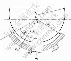
Fig.1 Structure of new type spherical air bearings
3 Mesh generation
The six air intakes are evenly distributed along the circumferential direction, and the ball head is not affected by the horizontal force when it is in the float state. Hence, the flow is axis-symmetrical. For air lubrication, the air film thickness is usually tens of microns, which is far smaller than the size of the other two directions, so it leads to the large aspect ratio of the mesh element. In order to reduce the truncation error as well as to avoid the numerical divergence, the unstructured hexahedral mesh and pyramid mesh are mainly used in mesh generation. Both the pressure and the velocity vary rapidly around the air intake and the air central outlet of ball socket, in which the structured hexahedral mesh and local mesh refinement method were used. Figures 2 and 3 illustrate the meshes generated in the entire computational domain and a close-up around an air intake, respectively.
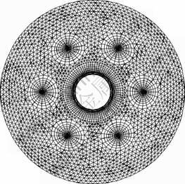
Fig.2 Mesh in computational domain
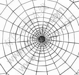
Fig.3 Mesh around air intake
4 Discretization and solution of governing equations
The governing equations for steady-state three- dimensional compressible flows can be found in Ref.[10].
The continuity equation is
![]() (1)
(1)
where div(��) is the divergence operator, �� is the density and u is the velocity vector.
The momentum equations are
 (2)
(2)
where u, v and w are the components of the velocity vector u on x, y and z axes, respectively; �� is the dynamic viscosity, grad is the gradient function, and p is pressure; Su, Sv and Sw are the generalized source terms of the momentum equations.
The energy equation is
![]() (3)
(3)
where T is the temperature, k is the heat transfer coefficient, cp is the specific heat, and ST is the viscous dissipation term.
In order to analyze and solve the above governing equations conveniently, those equations are rewritten in the following general form:
![]() (4)
(4)
where f is the general variable, and the general equation represents the continuity equation, the momentum equations and the energy equation when f is set as 1, u, v, w and the temperature T, respectively. �� and S are the generalized diffusion coefficient and generalized source term, respectively.
From Eq.(4), the integral of the general governing equation can be written as
![]() (5)
(5)
where P0 denotes the control volume, ![]() and
and ![]() are the volume and surface area of P0, respectively. A is the area vector of the control volume interface, which is composed of Aj (j=1, 2, ��, N). The positive direction of Aj coincides with the unit vector of the surface normal pointing outside, and N equals 6 and 5 for the hexahedral mesh and the pyramid mesh, respectively.
are the volume and surface area of P0, respectively. A is the area vector of the control volume interface, which is composed of Aj (j=1, 2, ��, N). The positive direction of Aj coincides with the unit vector of the surface normal pointing outside, and N equals 6 and 5 for the hexahedral mesh and the pyramid mesh, respectively.
For the control volume P0, Eq.(5) can be rewritten as
![]() (6)
(6)
where the items of the equation from left to right are convective term, diffusive term and source term.
4.1 Discretization of governing equations
The midpoint rule [11] is adopted in the discretization process to calculate both the surface integral and the volume integral. The former is approximated as the product of the integrand at the cell-face center and the cell-face area, and the latter is approximated as the product of the integrand at the cell-node center and the cell-node volume. Through discretizing the three items given in Eq.(6), the discretized governing equation for the control volume P0 can be obtained, and the generalized form is
![]() (7)
(7)
where a0 is the center coefficient, aj is the influence coefficient of the adjacent elements, and b0 is the constant of the source term.
4.2 Under-relaxation method
The under-relaxation technique is usually adopted in the numerical iteration to avoid potential divergence. For the discretized governing equations, the under-relaxation factor can be affiliated directly into the process of solving the algebraic equations, which means that the under-relaxation factor is contained in the main diagonal coefficient of the generated algebraic equations [12]. Therefore, the discrete governing equation given in Eq.(7) is rewritten as
![]() (8)
(8)
where ![]() denotes the under-relaxation factor of the variable f, and
denotes the under-relaxation factor of the variable f, and ![]() is the result of
is the result of ![]() from the last iteration.
from the last iteration.
4.3 Boundary conditions
The boundary conditions are implemented in accordance with the following steps:
Step 1: Let pi equal ps at the pressure inlet.
Step 2: Let pi equal pa at the pressure outlet.
Step 3: Let ?pi/?n equal zero at the periodic boundary, where n is the surface normal of the periodic boundary.
4.4 Solution of governing equations
A modified SIMPLE algorithm suitable for compressible flows is adopted to solve the discretized governing equations. The algorithm can be summarized as follows [13-14]:
Step 1: Start the iterative process by guessing the pressure field and density field, which are denoted by p* and ��*, respectively.
Step 2: Use the values of p* and ��* to solve u, v and w from the momentum equations. Since these velocities are associated with the values of p* and ��*, they are denoted by u*, v* and w*.
Step 3: Since they are obtained from the guessed values of p* and ��*, the values u*, v* and w*, when being substituted into the continuity equation, will not necessarily satisfy that equation. Hence, using the continuity equation, a pressure correction p�� is constructed. When it is added to p*, the velocity field gets more agreement with the continuity equation, that is, the ��corrected�� pressure p is
p=p*+p�� (9)
The velocity corrections u��, v�� and w�� as well as density correction �ѡ� can be obtained from p��, then the corresponding corrected items u, v, w and �� can be obtained:
 (10)
(10)
��=��*+�ѡ� (11)
Step 4: Return to Step 2, designate the corrected values p and �� as the new values of p* and ��*, and repeat the process until a velocity field is found that does satisfy the continuity equation.
4.5 Analysis of static characteristics
Upon the completion of the above computation, the pressure field and velocity field of the air bearing can be obtained, from which the carrying capacity, static stiffness and mass flow of the air bearings can be derived.
Evaluating the integral of pressure over the upper surface of the air film, the carrying capacity of the air bearing can be determined by
![]() (12)
(12)
where Aa denotes the upper surface area of the air film, Ai denotes the area vector of the i-th mesh, and n denotes the number of the meshes on the upper surface of the air film.
Defining KW=dW/dh as the static stiffness, in order to facilitate the calculation, the finite-difference method is applied to obtain the static stiffness of the air bearing:
![]() (13)
(13)
where ��h refers to the calculation step with respect to the central air film thickness, which is set as 0.5 ��m in this work.
Next, the mass flow can be obtained by using the following equation:
![]() (14)
(14)
where Ab denotes the area of the air intake, and m denotes the number of the meshes on the air intake section.
5 Computations and analysis
Upon the method of the above computation, the bearing capacity, static stiffness and mass flow of the new type externally pressurized spherical air bearings are considered, respectively.
The structural parameters of the air bearings are set as follows. The ball head radius is R1=50 mm, the ball socket radius is R2=50 mm, the wrap angle of air intake is ��1=30��, the outer wrap angle of ball socket is ��2=60��, the number of air intake is 6, and the air intake diameter is d0=1.2 mm. The air central outlet diameter of ball socket is d2=10 mm and the torsion rod diameter connected to ball head is d1=9 mm. The air parameters are set as follows. The ambient temperature is 20 ��C, the ambient pressure is standard atmospheric pressure, the air density is ��a=1.226 kg/m3, and the air dynamic viscosity is ��=1.833 Pa?s. The mesh parameters are set as follows. The number of points around the air outlet is 180, the number of points along the air film thickness direction is 20, and the total number of the meshes is 338 000.
5.1 Pressure distribution of bearings
When the air supply pressure is 0.4 MPa and the central air film thickness is 20 ��m, the pressure distribution of the new type externally pressurized spherical air bearings is shown in Fig.4. It can be seen that the pressure of near air intakes is the maximum, which can reach above 80% of air supply pressure. The pressure of circumference located in air intakes is basically the same, which is about 60% of air supply pressure. Due to the second closure effect of air outlet, the pressure damping on the inner side and outer side of circumference located in air intakes is relatively slow, and the pressure reaches 50% of air supply pressure.
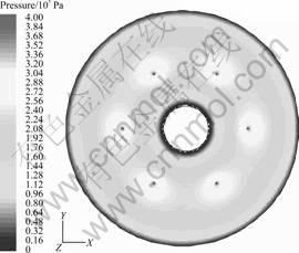
Fig.4 Pressure distribution of spherical gas bearing
When the central air film thickness is 20 ��m, the pressure distribution of across air intake center along radial axis of spherical air bearings is shown in Fig.5. It can be seen that after air outflows from the air intakes, there is a steep fall of pressure around the air intakes. This is due to the existence of air film, the size of throttle surface increasing, and the rapid increase of air flow velocity. As air film thickness increases, the high speed airflow in air bearings results in the production of a supersonic region near the air inlet because of the existence of shock waves, which is followed by a region where the conversion from supersonic flow to subsonic flow takes place [15-16]. But, the steep fall of pressure only exists in the smaller area near air intakes, which has little effect on the bearing capacity.
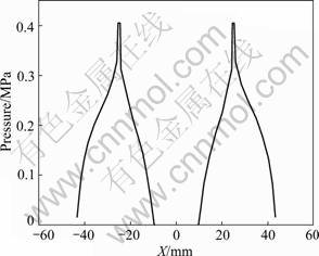
Fig.5 Pressure distribution of across air intake center along radial axis
5.2 Bearing capacity
When the air supply pressure is ps=0.2, 0.4, 0.6 MPa, the bearing capacity of the new type externally pressurized spherical air bearings varying with central film thickness is shown in Fig.6. It can be seen that if the air film thickness is less than 20 ��m, the bearing capacity slowly decreases as central air film thickness increases due to the throttle effect at air outlet; and if the air film thickness is greater than 20 ��m, the bearing capacity rapidly decreases as central air film thickness increases due to the weakening of throttle effect. For the same central air film thickness, the increase of air supply pressure results in the increase of the bearing capacity, and the bearing capacity and the air supply pressure are approximately in linearity. Therefore, for the same spherical air bearing, reducing the central air film thickness or increasing air supply pressure can increase its bearing capacity.

Fig.6 Bearing capacities of spherical air bearing varying with central film thickness
5.3 Static stiffness of bearings
When the air supply pressure is ps=0.2, 0.4, 0.6 MPa, the static stiffness of spherical air bearings varying with central film thickness is shown in Fig.7. It can be seen that for the same air film thickness, the higher the air supply pressure, the greater the static stiffness of spherical air bearings. As the air supply pressure increases from 0.2 to 0.6 MPa, the maximum static stiffness increases from 8.26 to 36.4 N/��m. The increase of static stiffness is very obvious. Therefore, in order to improve the static stiffness of spherical air bearings, it is the most effective means to increase the air supply pressure on the premise of ensuring the bearings stability. Under the different air supply pressures, the corresponding central air film thickness for the maximum static stiffness of spherical air bearings can be changed. As the air supply pressure is ps=0.2 MPa, the corresponding central air film thickness for the maximum static stiffness is 38 ��m; as the pressure is ps=0.4 MPa, the corresponding central air film thickness for the maximum static stiffness is 30 ��m; as the pressure is ps=0.6 MPa, the corresponding central air film thickness for the maximum static stiffness is 24 ��m. By contrasting Fig.6 and Fig.7, it can be found that the maximum static stiffness point and the maximum slope point of bearing capacity are coincident, which conforms the definition of static stiffness completely.
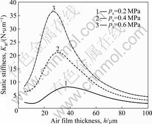
Fig.7 Static stiffnesses of spherical air bearing varying with central film thickness
5.4 Mass flow of bearings
When the air supply pressure is ps=0.2, 0.4, 0.6 MPa, the mass flow of spherical air bearings varying with central film thickness is shown in Fig.8. It can be seen that for the same air film thickness, the higher the air supply pressure, the greater the mass flow of spherical air bearings, and the mass flow is approximately proportional to the air supply pressure. This is because air is compressed and Mach number of bearing clearances increases as air supply pressure is increased. For the same air supply pressure, the mass flow of spherical air bearings increases as the central air film thickness increases because of the enlargement of air open area. Therefore, for the same spherical air bearing, reducing the air supply pressure or the central air film thickness can reduce the mass flow (air consumption) of the bearing. For the same load (bearing capacity), when the air supply pressure decreases, the central air film thickness reduces, which results in the decrease of the mass flow of spherical air bearing.
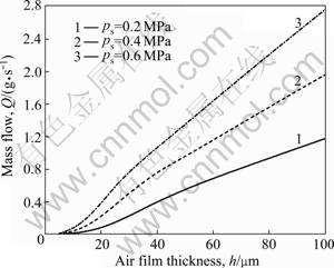
Fig.8 Mass flows of spherical air bearing varying with central film thickness
6 Conclusions
1) The pressure of near air intakes is the maximum, which can reach above 80% of air supply pressure. After air outflows from the air intakes, there is a steep fall of pressure around the air intakes.
2) The capacity of the new type externally pressurized spherical air bearings greatly increases as air supply pressure increases and the central air film thickness decreases. For the same central air film thickness, the bearing capacity and the air supply pressure are approximately in linearity. The static stiffness of bearings and the central air film thickness have similar parabolic relation. As the air supply pressure increases from 0.2 to 0.6 MPa, the maximum static stiffness increases by more than three times.
3) The mass flow of air bearings increases as air supply pressure and the central air film thickness increase. And the mass flow is approximately proportional to the air supply pressure and film thickness.
References
[1] RICHARD B, KURT W. A new high accuracy instrument for measuring moment of inertia and center of gravity [R]. Los Angeles: Society of Allied Weight Engineers, 1988.
[2] JAE J K, BRIJ N A. Automatic mass balancing of air-bearing-based three-axis rotational spacecraft simulator [J]. Journal of Guidance, Control, and Dynamics, 2009, 32(3): 1005-1017.
[3] SHAN J J. Dynamics and control of a tri-axis satellite attitude simulator [J]. Aircraft Engineering and Aerospace Technology, 2010, 82(2): 116-125.
[4] GUO Liang-bin, WANG Zu-wen, BAO Gang, LI Jun. Finite element analysis the pressure distribution of externally pressurized spherical air bearings with inherent compensation [J]. Tribology, 2004, 24(6): 531-535. (in Chinese)
[5] Space Electronics Inc. Combined center of gravity and moment of inertia measurement [EB/OL]. http://www.space-electronics.com/ Products/KSR_Series.php.
[6] MATTHEW C V, CHRISTOPHER D H. Decentralized coordinated attitude control within a formation of spacecraft [J]. Journal of Guidance, Control, and Dynamics, 2006, 29(5): 1101-1109.
[7] GROSSMAN R L. Application of flow and stability theory to the design of externally pressurized spherical gas bearings [J]. Journal of Basic Engineering, 1963, 12: 495-502.
[8] REN Di, WANG Zu-wen, YANG Qing-jun, BAO Gang. Effect of manufacturing errors on static characteristics of externally pressurized spherical air bearings [J]. Chinese Journal of Mechanical Engineering, 2009, 22(6): 896-902.
[9] REN Di, YANG Qing-jun, WANG Zu-wen, BAO Gang. Three dimensional calculation method of bearing capacity for externally pressurized spherical air bearings [J]. Journal of Dalian Maritime University, 2008, 34(2): 79-82. (in Chinese)
[10] VERSTEEG H K, MALALASEKERA W. An introduction to computational fluid dynamics: The finite volume method [M]. New Jersey: Prentice Hall, 2007: 10-25.
[11] FERZIGER J H, PERIC M. Computational methods for fluid dynamics [M]. Berlin: Springer-Verlag, 2002: 72-76.
[12] ZHANG Ling, ZHOU Jun-li, CHEN Xiao-chun, LAN Li, ZHANG Nan. Numerical simulation of flow around square cylinder using different low-Reynolds number turbulence models [J]. Journal of Central South University of Technology, 2008, 15(4): 564-568.
[13] ACHARYA S, BALIGA B R, KARKI K, MURTHY J Y, PRAKASH C, VANKA S P. Pressure-based finite-volume methods in computational fluid dynamics [J]. Journal of Heat Transfer, 2007, 129(4): 407-424.
[14] KIRIL S S, STEFAN K S. Pressure based finite volume method for calculation of compressible viscous gas flows [J]. Journal of Computational Physics, 2010, 229(2): 461-480.
[15] MOHAMED E, ELESHAKY. CFD investigation of pressure depressions in aerostatic circular thrust bearings [J]. Tribology International, 2009, 42(3): 1108-1117.
[16] SHIGEKA Y, MAKOTO Y, KAZUYUKI T. Numerical calculations of pressure distribution in the bearing clearance of circular aerostatic thrust bearings with a single air supply inlet [J]. Journal of Tribology, 2007, 129(4): 384-390.
(Edited by YANG Bing)
Foundation item: Project(2002AA742049) supported by the National High Technology Research and Development Program of China
Received date: 2010-05-28; Accepted date: 2010-09-14
Corresponding author: WANG Fu-sheng, PhD Candidate; Tel: +86-451-86412443-233; E-mail: wangfs0822@163.com
