
Trans. Nonferrous Met. Soc. China 28(2018) 920-930
Influences of gap size and cyclic-thermal-shock treatment on mechanical properties of TLP bonded IN-738LC superalloy
Vahid MALEKI1, Hamid OMIDVAR1, Mohammad-Reza RAHIMIPOUR2
1. Department of Mining and Metallurgical Engineering, Amirkabir University of Technology (Tehran Polytechnic), Tehran 15875-4413, Iran;
2. Department of Ceramic, Materials and Energy Research Center, Karaj 31787-316, Iran
Received 19 September 2016; accepted 18 April 2017
Abstract:
Influences of gap size and cyclic-thermal-shock treatment on the mechanical properties of transient liquid phase (TLP) bonded IN-738LC superalloy were investigated. For this purpose, TLP bonding of IN-738LC superalloy was carried out in a vacuum furnace using powdered AMS 4777 as the filler metal. The results showed that isothermal solidified zone (ISZ) consisted of Ni solid-solution and the distribution of alloying elements was homogeneous. High hardness of HV 409 and high shear strength of 506 MPa were observed in 40 ��m gap sample. Alloying elements formed �á� precipitates and the solid-solution in the ISZ. Hardness and shear strength of bonds were reduced with increasing the gap size (in range of 40-120 ��m). The fractured surfaces of complete isothermal solidified bonds showed dimpled rupture, but athermal solidified bonds showed cleavage fracture surface. 10, 20, 30 and 40 thermal-shock cycles were applied to 80 ��m gap samples, respectively. The shear strength of the bond was measured to be 268 MPa after the 40th thermal-shock cycle. The sample with gap size of 80 ��m was failed due to crack nucleation on faying surface at 45th thermal-shock cycle. The amount of the produced brittleness due to quenching the samples in water bath was attributed to the number of thermal-shock cycles.
Key words:
IN-738 superalloy; TLP bonding; mechanical properties; cyclic-thermal-shock treatment; shear strength;
1 Introduction
BIEBER et al patented IN-738 as an investment casting Ni-based superalloy in 1969 [1]. It is produced in two different versions of low-carbon (IN-738LC) and high-carbon (IN-738C). IN-738LC superalloy is a high-temperature alloy due to the presence of �á� precipitates (significantly in Ni3Al) in a �� solid-solution matrix. This alloy is widely used in hot sections of gas-turbine engines because of its excellent high-temperature mechanical properties and hot corrosion resistance [2,3]. It is of great importance in aerospace industry, since there is often no substitute for it in this industry. Other typical applications include stator parts such as vanes and integral wheels [4].
Welding processes are often inappropriate for bonding precipitation hardened Ni-base superalloys because of their susceptibility to fusion zone and heat affected cracking [5-7]. It is reported that the welds exhibited detrimental specifications decreasing high-temperature properties. The conventional brazing processes are suggested as an alternative approach for bonding these alloys [8].
TLP bonding is a diffusion brazing process patented by PAULONIS et al in 1971 [9]. It is a flexible process for joining non-weldable superalloys because it enjoys the advantages of both brazing and solid-state diffusion bonding. The eutectic compounds achieved during the TLP process are detrimental to mechanical properties of bonds. This technique is superior to conventional brazing, since it can achieve a free eutectic compound [10,11].
A filler alloy with a lower melting point than the base alloy is almost similar chemical composition; it is often pre-placed inter-gaps in TLP bonding, while all parts are heated to a bonding temperature afterwards. The TLP bonding involves three stages: 1) melting the braze alloy which in turn dissolves the substrate due to heating; 2) increasing the solidus and liquidus temperatures of the filler due to equilibrium state and increasing diffusion into the base alloy; and 3) the liquid begins to solidify by the diffusion of melting point depressant (MPD) elements into the base alloy [12-14]. Additionally, homogenization stage can exist as a supplementary stage for this process.
Complete isothermal solidified (CIS) bond can be made by the diffusion of MPD elements such as boron and silicon into the base metal; afterwards, a proper bond quality can be achieved. Certain value of holding time is required to obtain a CIS bond with good microstructure and mechanical properties [15]. Hence, when the holding time is low, athermal solidification of the residual liquid phase leads to the formation of brittle eutectic compounds. These compounds decrease mechanical strength, service temperature, and corrosion resistance of the bonds compared to the free eutectic bonds [16]. Even though the TLP bonding uses the isothermal solidification to prevent the formation of brittle phases in the bonding zone, it is limited to the small gaps not exceeding 250 ��m [17]. Therefore, the key advantage of the TLP bonding is the proper process optimization to prevent the formation of the eutectic compounds [18].
Low cycle fatigue and stress-rupture properties of bonds brought about by the diffusion brazing were about 90% and 85% of their base metal properties, respectively [19]. SHAKERIN et al [20] also reported that the shear strength of the bonds made by the TLP bonding process was measured to be more than 80% of the base metal shear strength. TLP is expected to generate high-strength bonds with excellent properties when proper optimized process parameters of bonding treatment are used.
A great number of researchers have investigated the microstructural and mechanical evolution taking place in TLP bonds due to changes in filler alloy composition, bonding time, heat treatment and bonding temperature. But, no research activities have been performed on the effect of cyclic-thermal-shock treatment, but only a few research activities have been carried out on the effect of the gap size on the mechanical properties of the TLP bonds in a large range. The present research is based on previous findings of other studies; it aims to determine mechanical changes for 40, 80, 120, 160, and 200 ��m gap bonds and also thermal-shock properties of the 80 ��m gap bonds.
2 Experimental
2.1 Materials
IN-738LC superalloy and AMS 4777 paste (American Welding Society designation BNi-2) with chemical compositions shown in Table 1 were used as the base alloy and filler alloy, respectively. Liquidus temperatures of the base alloy and filler alloy were 1315 and 1038 ��C respectively. Their solidus temperatures were 1230 and 966 ��C, respectively.
2.2 Experimental techniques
The base alloy was divided into 100 mm �� 10 mm �� 5 mm pieces by a wire electro discharge machine (WEDM) and their faying surfaces were polished by 60- to 1200-grade SiC paper to remove oxide layers formed during WEDM cutting. The pieces were ultrasonically cleaned in an acetone bath for 20 min to remove surface contaminants. Fixed gap (40, 80, 120, 160 and 200 ��m) specimens (100 mm �� 10 mm �� 10 mm) were produced using 40 and 60 ��m thick stainless steel spacers between the two base metal pieces (Fig. 1(a)). A stainless steel fixture was used to prevent the movement of the parts in the furnace (Fig. 1(b)). The filler alloy, in a paste form, was preplaced above the fixed gap; afterwards, all parts were immediately placed in the tubular vacuum furnace for TLP bonding operation.
Table 1 Chemical composition of base alloy and used filler alloy (mass fraction, %)
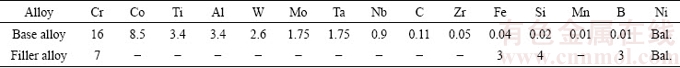

Fig. 1 Schematic illustration of specimen before TLP operation (a), used fixture during operation (b), position of shear, hardness and microscopic examination samples on specimen after operation (c) (unit: mm)
TLP bonding temperature for all specimens was selected to be 1120 ��C and the operation was performed under a vacuum of approximately 5.32��10-3 Pa. Furnace heating rate was about 15 ��C/min and the specimens were furnace-cooled to room-temperature (20 ��C) after bonding. Cooling rate of furnace was about 6 ��C/min. The minimum retention time in the furnace to form CIS bond was obtained to be 45, 60 and 105 min for 40, 80 and 120 ��m specimens, respectively. Retention time for 160 and 200 ��m gaps was 120 min, but no CIS bond was observed. These data were also reported in other study [21]. Different samples for intended tests were cut perpendicularly to their bonding zone from TLP bonded specimens by a WEDM (as shown in Fig. 1(c)). 10 mm �� 10 mm �� 5 mm sections were named ��samples A�� and used to microhardness test, optical microscopy test and SEM-EDS analysis. 10 mm �� 10 mm �� 10 mm sections were named ��samples B�� and used to shear strength test and cyclic-thermal-shock treatment. Remaining sections (part C) were discarded.
Optical microscope (OM) tests were performed by a POLYVAR-Reichert-Jung optical microscope. Intended samples were etched by Kalling��s reagents with 1.5 g CuCl2, 33 mL HCl, 33 mL H2O and 33 mL ethanol to run the tests. Micro X-ray diffraction (XRD) method was performed by a PHILIPS machine using Cu K�� radiation with 10�� and 80�� start and end angles, to determine different phases of fractured surfaces after shear strength tests. Furthermore, CAMBRIDGE 360 scanning electron microscope (SEM) was used to study fracture surfaces. A MIRA TESCAN scanning electron microscope equipped with an energy dispersed X-ray spectrometer system was applied to SEM-EDS analysis.
2.3 Cyclic-thermal-shock treatment
Parts made of the IN-738LC superalloy work at high temperatures, therefore thermal-shock affects their service life, because those often work above 700 ��C. To study the impact of the number of thermal-shock cycles on bond��s mechanical properties, cyclic-thermal-shock treatment was carried out in this research.
Cyclic-thermal-shock treatment was only performed on 80 ��m gap samples under CIS condition. For this purpose, samples were positioned in an electric resistance oven with the heating rate of 2.75 ��C/s. At each thermal-shock cycle, the sample was put in the oven at 700 ��C for 10 min and then, immediately quenched in a room-temperature (20 ��C) water bath (Fig. 2(a)). This treatment can be considered as a cyclic-thermal-shock treatment, since no thermal stress was applied to samples during the thermal cycle. This process was performed for 10, 20, 30, 40 and 45 cycles, and then shear strength test was carried out on the samples. The fracture surfaces of the shear samples were studied using SEM and the location of the crack nucleation and crack diffusion path were evaluated. Quantitative and qualitative measurements were obtained to characterize fracture modes before and after thermal-shock treatment.
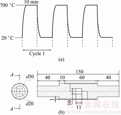
Fig. 2 Schematic illustration of sequences of cyclic-thermal-shock treatment (a) and shear test fixture (unit: mm) (b)
2.4 Mechanical evaluation
Microhardness across the bonding zone was measured by a CV microhardness tester with a 50 g load on bonds. An average of five measurements was obtained for each point according to the ASTM standard E384. Room-temperature (20 ��C) shear strength test was carried out on samples. The test was carried out at a cross-head speed of 1 mm/min using a SANTAM STM-600 tensile machine in accordance with ASTM standard D1002-05. The shear strength measurements were reported as an average of three measurements. A cylindrical fixture (Fig. 2(b)) was used on the tensile machine to apply shear stress on the bonds during the shear test.
3 Results and discussion
3.1 Bond microstructure
During the TLP bonding process, the filler alloy melts at the bonding temperature and brings about a liquid phase formed between the faying surfaces of the base metals. Si and B in the chemical composition of the filler alloy are MPD elements [22]. Therefore, when the filler alloy melts, these elements diffuse into the base metal and increase the melting point of the filler alloy. Consequently, the filler alloy starts to solidify at bonding temperature.
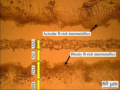
Fig. 3 Optical micrograph of undesirable bond (athermally solidified) for 120 ��m gap sample prepared at 60 min
At the TLP bonding, an undesirable bond (Fig. 3) has four distinct zones as: ASZ (athermal solidified zone), ISZ, DAZ (diffusion affected zone), and base metal (BM). But, this bond will be a suitable bond if ASZ is removed by increasing temperature or retention time in the furnace. For each bonding temperature, a minimum bonding time is required to remove eutectic compounds from the bond area and improve its shear strength [23]. Based on the investigations [1], the microstructure of ASZ is not homogeneous. It consists of Ni solid-solution, Ni-rich and Cr-rich borides which are hard and brittle and are formed by a eutectic-type transformation. These phases are detrimental to the mechanical properties of the bonds. The microstructure of ISZ contains Ni solid-solution and is homogeneous [3]. The homogeneity around the centerline of a 40 ��m gap bond was observed by SEM/EDS X-ray mapping which is depicted in Fig. 4. This figure indicated that the distribution of the elements was homogeneous in the bond area without eutectic compound. JALILVAND et al [2,5] reported the EDS X-ray mapping of a bond area with eutectic compounds which was not homogeneous. Another zone is DAZ, which consists of extensive blocky and acicular B-rich intermetallics as depicted in Fig. 3. These intermetallics are formed because of the diffusion of B from bond zone to the base alloy. Their density is increased near the interface of the base metal and bonding area. The fourth zone is base metal which does not often perform any important evolution in TLP bonding. According to other articles, CIS bond will be made if the whole gap area is formed by ISZ after TLP bonding [20,21].
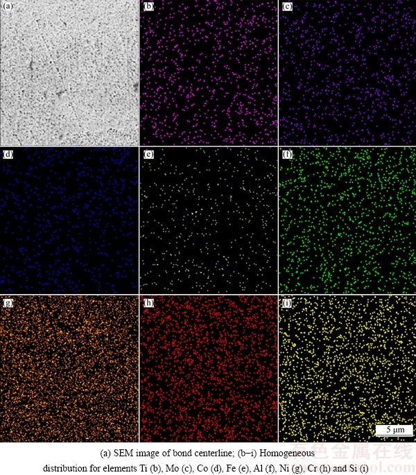
Fig. 4 SEM/EDS X-ray mapping over ISZ centerline for 40 ��m gap sample
Optical micrographs of different bonds (athermal and isothermal solidified) are observed in Fig. 5. The figure illustrates different CIS bonds. In addition, athermal solidification for 160 and 200 ��m gaps samples is shown in the figure. Eutectic constituents in the centerline of 160 and 200 ��m gaps bonds are made because of athermal solidification.
3.2 Microhardness evaluation
In TLP bonding, solid state diffusion of the alloying elements entering the base metal area and the bonding region determines the ISZ hardness. Figure 6 shows ISZ microhardness for different CIS bonds. According to the figure, ISZ hardness was reduced with increasing the gap size from 40 to 120 ��m. This result is consistent with the findings of BAKHTIARI and EKRAMI [19] in the TLP bonded FSX-414 superalloy.
Increasing the gap size led to increasing penetration distance of elements from the base metal into the bond centerline and volume size in which the elements were distributed. Therefore, the distribution of alloying elements such as Al and Ti in larger gaps was lower. These elements led to the formation of �á� precipitates and improved the mechanical properties of the bond. Solid-solution elements such as Co also raised the ISZ hardness [5]. High hardness of HV 409 was observed in 40 ��m gap bond associated with higher �á� precipitates in the ISZ. Figure 7 illustrates the amount of diffused alloying elements from the base metal into the ISZ for different samples. According to this figure, higher presence of alloying elements such as Co, Al, Ti, W, Mo, and Nb in the centerline of the 40 ��m gap is depicted. Therefore, 40 ��m gap bond had more concentration of alloying elements in comparison with 80 and 120 ��m gaps. Thus, it was observed that the presence of these elements was commensurate with the ISZ hardness.
The microhardness profile across the bond area is a quantitative indication of mechanical property variation and used to find the effect of secondary precipitated phases on the bond��s mechanical properties [14].
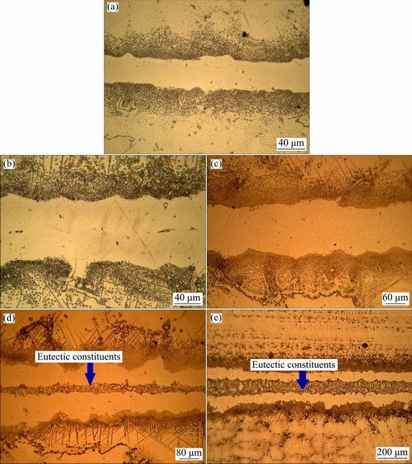
Fig. 5 Optical micrographs of bonded samples with 40 ��m (a), 80 ��m (b), 120 ��m (c), 160 ��m (d) and 200 ��m (e) gaps, respectively
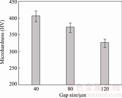
Fig. 6 Microhardness variations of ISZ for different CIS gaps at load of 50 g
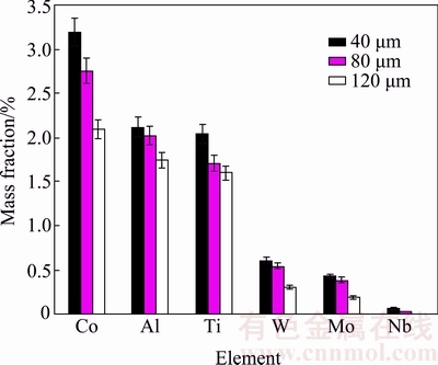
Fig. 7 Mass fractions of elements obtained from SEM/EDS of ISZ centerline at 40, 80 and 120 ��m gaps in CIS condition
Figure 8 shows the microhardness profile for 40, 80 and 120 ��m gaps samples. This figure indicates two distinct zones (ISZ and DAZ). ISZ hardness is increased near the faying surface. Approaching the faying surface results in the increase in the diffused alloying elements into ISZ; thus, more �á� precipitates are present on faying surface. The increase in hardness due to the presence of significantly more Ti and Al near the faying surface was also reported in other study [20]. DAZ is the second zone with a hardness peak. The peak can be attributed to the stable B-rich brittle intermetallic compounds in the bonding temperature made from Cr-B and Ni-B systems.
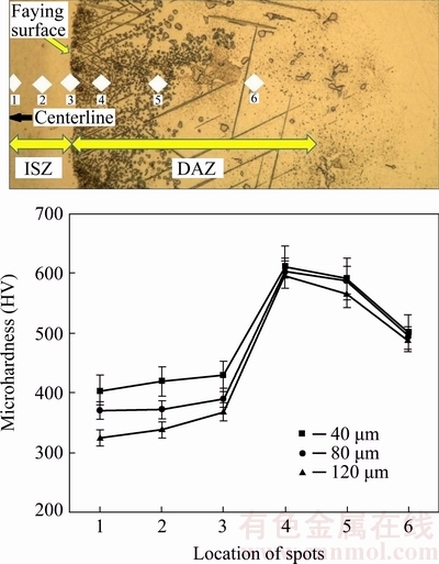
Fig. 8 Microhardness profile over half of bond area for different CIS gaps at load of 50 g
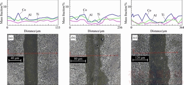
Fig. 9 SEM/EDS line scan over bonding area of CIS bonds at 40 ��m (a), 80 ��m (b) and 120 ��m (c) gaps
Figure 9 illustrates that a wider gap has a lower amount of diffused alloying elements from the base metal into the bond region. The elements are the causes for the formation of �á� precipitates. Therefore, lower microhardness was attributed to the less alloying elements such as Al, Ti, and Co in the bond area.
3.3 Shear strength evaluation
To further investigate the mechanical properties of TLP bonds, shear strength evaluation was performed by the application of shear stress to the bond area. 40, 80, and 120 ��m gaps samples were CIS and free from any centerline eutectic compounds. Two samples (160 and 200 ��m) were athermal solidified (Fig. 5).
High shear strength of 506 MPa was observed in 40 ��m gap bond (Fig. 10). Shigley��s Mechanical Engineering Design Textbook [24] suggested that the shear strength of a homogeneous metal should be considered about 0.6 of its tensile strength. Accordingly, tensile strength of 40 ��m gap bond will be 843 MPa. The tensile strength of the base metal is 1033 MPa, hence, tensile strength of a 40 ��m gap sample is achieved at about 82% of the base metal. Since IN-738LC superalloy is a high strength alloy, attaining 82% of strength can be an acceptable strength for a bond. For the CIS bonds which have no eutectic compounds in their bond areas, the bond shear strength is proportional to the �á� precipitates whose solvus temperature is 1160-1175 ��C [25]. Hence, those were not dissolved at the bonding temperature.
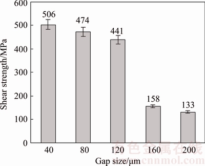
Fig. 10 Shear strength variations of TLP bonds for different gaps
As previously mentioned in Section 3.2, narrower gap has more �á� precipitates than wider one. However, increasing the gap size enhances the possibility of the existence of defects such as grain boundary defects; therefore, a wider gap will have a wider weak area. According to Fig. 10, shear strength of CIS bonds is decreased with increasing the gap size (in the range of 40-120 ��m). This result is proportional to the microhardness data in Section 3.2. The ratio of the hardness of bond to its shear strength was also reported in several studies [20,26,27].
160 ��m gap sample in comparison with 120 ��m gap has a great reduction of shear strength. It is attributed to the existence of centerline eutectic compounds in a 160 ��m gap (Fig. 10). As seen in Fig. 5, 200 ��m gap has a thicker continuous centerline eutectic compared to 160 ��m gap, which can be attributed to increasing the diffusion distance of elements in 200 ��m gap. This thicker centerline eutectic is the cause of the lower strength of a 200 ��m gap compared to a 160 ��m gap. As noted earlier, the centerline eutectic is a brittle, hard, and continuous phase; on the contrary, the applied shear force is not flexible and causes crack initiation in the bond area. The improvement of the bond��s shear strength with a decrease in the width of centerline eutectic was reported by JALILVAND et al [2]. Furthermore, 200 ��m gap has a wider DAZ compared to a 160 ��m gap, but this wider DAZ does not have any significant effect on the shear strength of the bond, since its intermetallic compounds are discontinuous. However, the shear failure of TLP-bonded samples often occurs in a bond area not in the BM (because of the weaker mechanical properties of the bond compared to that of the BM). JALILVAND et al [5] have also shown that discontinuous intermetallic compounds in the DAZ have less detrimental effect on the shear strength of the bond compared to continuously distributed compounds along the bond/BM interface.
Various intermetallic compounds form at the joint interface during the TLP bonding process [28]. To examine the fractured surfaces and to discuss the fracture mode of shear test samples, their micro XRD patterns are presented in Fig. 11. This figure shows different phases on the fracture surfaces for different gaps. For example, Ni solid-solution (��) is illustrated for 40, 80 and 120 ��m gaps samples. Ni solid-solution is a high rough phase which leads to ductile fracture [1,2]. In contrast, brittle B-rich phases are harmful to the superior properties of the bond [6,19] as demonstrated for 160 and 200 ��m gaps samples. The the bond area has been a ��-single phase in 40, 80 and 120 ��m gaps samples, whereas it has been a multiple-phase in 160 and 200 ��m gaps samples. The dimpled fracture of a ��-single phase was reported by other researchers [20].
Multiple sources [29-31] believe that dimples and cleavage surfaces are characteristics of ductile and brittle fracture, respectively. The results of the investigations performed on the morphology of fractured surfaces of shear test samples are shown in Fig. 12. Ductile fracture in alloys occurs by the mechanism of microvoids nucleation around the rigid inclusions [29]. Since the plastic flow of the matrix during strain exertion can occur around the inclusions, the matrix may become disparted and cracks germinate [30]. But, in a ductile fracture mode, the major contribution of stress is to crack propagation controlled by the crack growth. Hence, the higher number of dimples per unit area on the fractured surfaces is a good factor to increase the strength of material. According to Figs. 12(a), (b), and (c), the fracture mode has been ductile dimpled in 40, 80 and 120 ��m gaps sample. The yellow arrows in these figures show the dimpled locations. In Fig. 12(a), dimples are finer and in greater numbers than those in Fig. 12(b). In Fig. 12(c), dimples are coarser and in smaller numbers than those in Fig. 12(b). As a result, the greater shear strength of 40 ��m gap in comparison with 80 and 120 ��m gaps is justified. It seems that for CIS bonds, increasing the gap size leads to the decrease in the number of dimples and the increase in their size.
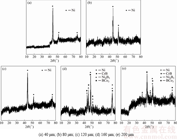
Fig. 11 XRD patterns of fractured surfaces for different gaps

Fig. 12 SEM images of fractured surfaces for 40 ��m (a), 80 ��m (b), 120 ��m (c), 160 ��m (d) and 200 ��m (e) gaps samples
Brittle cleavage fracture against ductile fracture is controlled by crack nucleation which often occurs on low index crystallographic planes and affects the bond rupture along these planes. It has a weak dependence on temperature and is usually characterized by the presence of river lines [30]. In this fracture mode, a major contribution of stress is made to crack the nucleation which quickly grows after the nucleated crack.
As mentioned above, eutectic compounds in bond centerline (ASZ) of 160 and 200 ��m gaps samples are hard and brittle. Consequently, those lack the five active slip systems required for homogeneous plastic deformation [29-31]. Accordingly, stress concentration occurs at points of discontinuity such as B-rich phase in ASZ. In accordance with Figs. 12(d) and (e), the fracture mode in 160 and 200 ��m gaps samples is brittle cleavage. The yellow arrows in Figs. 12(d) and (e) show the location of the river lines (to show the river line, magnification of Figs. 12(d) and (e) has increased relative to Figs. 12(a), (b), and (c)). The fractured surface of 200 ��m gap sample shows larger cleavage surfaces, which are probably created due to wider ASZ in the bond area. A wider ASZ causes to more stress concentration in bond area and therefore faster propagation of crack in nucleation resulting in failure. As a result, the lower shear strength of 200 ��m gap in comparison with 160 ��m is justified.
3.4 Cyclic-thermal-shock treatment
��Thermal-shock phenomenon was first studied thoroughly by KINGERY in 1955�� [30]. When material is exposed to rapid temperature change, which leads to sudden changes in local stress/strain stages, crack nucleation and growth will occur due to cracking under down quench. Such fractures are often characterized as the thermal-shock response of the material.
Figure 13 demonstrates the effect of the number of thermal-shock cycles on shear strength of TLP bonds. Increasing the number of thermal-shock cycles has led to a decrease in the shear strength of the bonds. After 40th thermal-shock cycle, shear strength of the bond was obtained to be 268 MPa. The bond failed at 45th thermal-shock cycle, so, cracking was established all along the bond area (Fig. 14). Thermal-shock failure occurs in metals, polymers, or ceramics; however, it occurs more in ceramics due to their intrinsic brittleness [30].
Applying cyclic-thermal-shock treatment to 80 ��m gap TLP bonds indicated that each bond endured a number of thermal-shock cycles without fail. In fatigue discussion, HERTZBERG [29] stated that crack nucleation occurred due to defects in metal. So, crack nucleation probably occurred due to stress concentration on defects and microcracks in the bond area. The location of crack nucleation, which has brought about the failure of the bond, has been on the faying surface. The area is a suitable location to form alloying precipitates (Fig. 14). Crack nucleation on faying surface of TLP bond has also been reported by other researchers [32].
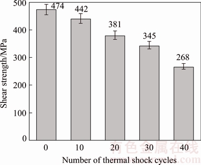
Fig. 13 Shear strength variations of bonds with 80 ��m gap after cyclic-thermal-shock treatment
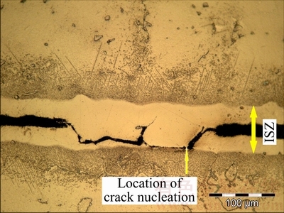
Fig. 14 Optical micrograph illustrating crack nucleation on faying surface of 80 ��m gap sample at 45th thermal-shock cycle
Fractured surfaces of thermal-shocked TLP bonds illustrated a brittle behavior during the shear strength test. The brittleness was due to the formation of microcracks on the fractured surfaces of thermal-shocked TLP bonds depicted in Fig. 15. Quench environment is an effective factor in thermal-shock resistance of the material, for example, ��BeO (beryllium oxide) exhibits much better shock resistance than aluminum oxide (Al2O3) when both materials are air quenched, but there are different results when both are water quenched�� [33]. Therefore, the amount of produced brittleness due to quenching the samples in water bath, which was observed on the fractured surfaces, was attributed to the number of thermal-shock cycles. Accordingly, created microcracks, observed on the fractured surfaces, were attributed to a decrease in the shear strength of the bond. In comparison with Fig. 15(a), Fig. 15(b) illustrates larger cleavage surfaces during the shear test, which are more critical and can be attributed to more brittleness in the bond area. Accordingly, the greater shear strength of the 10th cycle sample is consistent with the characteristics of their fractured surfaces compared to the 40th cycle sample. However, fracture mode has been in cleavage form in both. Additionally, after cyclic-thermal-shock treatment, river lines have no possible effect on the fractured surfaces.

Fig. 15 SEM images of fractured surface of 80 ��m gap sample
4 Conclusions
1) TLP bonding of IN-738LC nickel-based superalloy, using powdered AMS 4777 filler metal was carried out at 1120 ��C. CIS bonds were prepared at a minimum required holding time.
2) CIS bonds showed homogeneous distribution of alloying elements around the centerline and fracture surfaces of those showed that with an increase in the gap size, the number of dimples per unit area was decreased, but size of dimples was increased.
3) ISZ microhardness and shear strength were reduced with increasing the gap size.
4) For athermal solidified bonds, the characteristic of fracture was absolutely brittle cleavage, because those showed river lines at fractured surfaces.
5) Each bond endured a number of thermal-shock cycles without fail. The amount of the produced brittleness due to quenching the samples in water was attributed to the number of cycles.
References
[1] MOSALLAEE M, EKRAMI A, OHSASA K, MATSUURA K. Microstructural evolution in the transient-liquid-phase bonding area of IN-738LC/BNi-3/IN-738LC [J]. Metallurgical and Materials Transactions A, 2008, 39A: 2389-2402.
[2] JALILVAND V, OMIDVAR H, SHAKERI H R, RAHIMIPOUR M R. A study on the effect of process parameters on the properties of joint in TLP-bonded Inconel 738LC superalloy [J]. Metallurgical and Materials Transactions B, 2013, 44: 1222-1231.
[3] JALILVAND V, OMIDVAR H, SHAKERI H R, RAHIMIPOUR M R. Microstructural evolution during transient liquid phase bonding of Inconel 738LC using AMS 4777 filler alloy [J]. Materials Characterization, 2013, 75: 20-28.
[4] WIKSTROM N P, OJO O A, CHATURVEDI M C. Influence of process parameters on microstructure of transient liquid phase bonded Inconel 738LC superalloy with Amdry DF-3 interlayer [J]. Materials Science and Engineering A, 2006, 417: 299-306.
[5] JALILVAND V, OMIDVAR H, RAHIMIPOUR M R, SHAKERI H R. Influence of bonding variables on transient liquid phase bonding behavior of nickel based superalloy IN-738LC [J]. Materials and Design, 2013, 52: 36-46.
[6] EGBEWANDE A T, CHUKWUKAEME C, OJO O A. Joining of superalloy Inconel 600 by diffusion induced isothermal solidification of a liquated insert metal [J]. Materials Characterization, 2008, 59: 1051-1058.
[7] POURANVARI M, EKRAMI A, KOKABI A H. Diffusion brazing metallurgy of IN718/Ni-Cr-Si-B-Fe/IN718 [J]. Welding Research, 2014, 93: 60-68.
[8] ABDELFATAH M M, OJO O A. On the extension of processing time with increase in temperature during transient-liquid phase bonding [J]. Metallurgical and Materials Transactions A, 2009, 40: 377-385.
[9] COOK III G O, SORENSEN C D. Overview of transient liquid phase and partial transient liquid phase bonding [J]. Materials Science, 2011, 46(16): 5305-5323.
[10] WIKSTROM N P, EGBEWANDE A T, OJO O A. High temperature diffusion induced liquid phase joining of a heat resistant alloy [J]. Alloys and Compounds, 2008, 460: 379-385.
[11] CAO J, WANG Y F, SONG X G, LI C, FENG J C. Effects of post-weld heat treatment on microstructure and mechanical properties of TLP bonded Inconel718 superalloy [J]. Materials Science and Engineering A, 2014, 590: 1-6.
[12] GALE W F, BUTTS D A. Transient liquid phase bonding [J]. Science and Technology of Welding and Joining, 2004, 9(4): 283-300.
[13] POURANVARI M, EKRAMI A, KOKABI A H. Transient liquid phase bonding of wrought IN718 nickel based superalloy using standard heat treatment cycles: Microstructure and mechanical properties [J]. Materials and Design, 2013, 50: 694-701.
[14] POURANVARI M. TLP bonding of a gamma prime strengthened superalloy using Ni-Si-B interlayer at 1150 ��C. Part II: Mechanical properties [J]. World Applied Sciences, 2011, 15(11): 1507-1511.
[15] POURANVARI M, EKRAMI A, KOKABI A H. Effect of the bonding time on the microstructure and mechanical properties of a transient-liquid-phase bonded IN718 using a Ni-Cr-B filler alloy [J]. Materials and Technology, 2013, 47(5): 593-599.
[16] POURANVARI M. Isothermal solidification during transient liquid-phase bonding of GTD-111/Ni-Si-B/GTD-111 [J]. Materials and Technology, 2014, 48(1):113-118.
[17] YANG Y H, XIE Y J, WANG M S, Ye W. Microstructure and tensile properties of nickel-based superalloy K417G bonded using transient liquid-phase infiltration [J]. Materials and Design, 2013, 51: 141-147.
[18] GHONEIM A, OJO O A. Microstructure and mechanical response of transient liquid phase joint in Haynes 282 superalloy [J]. Materials Characterization, 2011, 62: 1-7.
[19] BAKHTIARI R, EKRAMI A. The effect of gap size on the microstructure and mechanical properties of the transient liquid phase bonded FSX-414 superalloy [J]. Materials and Design, 2012, 40: 130-137.
[20] SHAKERIN S, OMIDVAR H, MIRSALEHI S E. The effect of substrate��s heat treatment on microstructural and mechanical evolution of transient liquid phase bonded IN-738 LC superalloy [J]. Materials and Design, 2016, 89: 611-619.
[21] MALEKI V, OMIDVAR H, RAHIMIPOUR M R. Effect of gap size on microstructure of the transient liquid phase bonded IN-738LC superalloy [J]. Transactions of Nonferrous Metals Society of China, 2016, 26: 437-447.
[22] LIN T S, LI H X, HE P, YANG X, HUANG Y D, LI L, HAN L. Effect of bonding parameters on microstructures and properties during TLP bonding of Ni-based super alloy [J]. Transactions of Nonferrous Metals Society of China, 2012, 22: 2112-2117.
[23] BAKHTIARI R, EKRAMI A, KHAN T I. The effect of TLP bonding temperature on microstructural and mechanical property of joints made using FSX-414 superalloy [J]. Materials Science and Engineering A, 2012, 546: 291-300.
[24] BUDYNAS R, NISBETT K. Shigley��s mechanical engineering design [M]. 10th ed. New York: McGraw-Hill, 2014.
[25] DONACHIE M J, DONACHIE S J. Superalloys: A technical guide [M]. 2nd ed. Ohio: ASM International, 2002.
[26] POURANVARI M, EKRAMI A, KOKABI A H. TLP bonding of cast IN718 nickel based superalloy: Process�Cmicrostructure�Cstrength characteristics [J]. Materials Science and Engineering A, 2013, 568: 76-82.
[27] POURANVARI M, EKRAMI A, KOKABI A H. Microstructure�C properties relationship of TLP-bonded GTD-111 nickel-base superalloy [J]. Materials Science and Engineering A, 2008, 490: 229-234.
[28] SAMAVATIAN M, HALVAEE A, AMADEH A A, KHODABANDEH A. Transient liquid phase bonding of Al 2024 to Ti-6Al-4V alloy using Cu-Zn interlayer [J]. Transactions of Nonferrous Metals Society of China, 2015, 25: 770-775.
[29] HERTZBERG R W. Deformation and fracture mechanics of engineering materials [M]. 4th ed. New York: John Wiley & Sons, 1996.
[30] SOBOYEJO W. Mechanical properties of engineered materials [M]. New York: CRC Press, 2002.
[31] MILLS K. Metals handbook: Fractography (Volume 12) [M]. 9th ed. Ohio: ASM International, 1989.
[32] SEYYED AFGHAHI S S, EKRAMI A, FARAHANY S, JAHANGIRI A. Fatigue properties of temperature gradient transient liquid phase diffusion bonded Al7075-T6 alloy [J]. Transactions of Nonferrous Metals Society of China, 2015, 25: 1073-1079.
[33] LU T J, FLECK N A. The thermal shock resistance of solids [J]. Acta Materialia, 1998, 46(13): 4755-4768.
��϶�ߴ��ѭ���ȳ��������˲ʱҺ����ɢ����IN-738LC���ºϽ���ѧ���ܵ�Ӱ��
Vahid MALEKI1, Hamid OMIDVAR1, Mohammad-Reza RAHIMIPOUR2
1. Department of Mining and Metallurgical Engineering, Amirkabir University of Technology (Tehran Polytechnic), Tehran 15875-4413, Iran;
2. Department of Ceramic, Materials and Energy Research Center, Karaj 31787-316, Iran
ժ Ҫ���о���϶�ߴ��ѭ���ȳ��������˲ʱҺ����ɢ����IN-738LC���ºϽ���ѧ���ܵ�Ӱ�졣�÷�ĩ״ AMS 4777��Ϊ���������¯�ж�IN-738LC���ºϽ����˲ʱҺ����ɢ�������顣���������������������Ni��������ɣ��ҺϽ�Ԫ�طֲ����ȡ���϶�ߴ�Ϊ40 ��m����Ʒ����HV409�ĸ�Ӳ�Ⱥ�506 MPa�ĸ�ǿ�ȡ��ڵ������������Ͻ�Ԫ���γɦá������༰Ni�����塣�Ͻ����Ӵ���Ӳ�Ⱥ�ǿ�����϶�ߴ�(40~120 ��m)����������͡���ȫ�����������Ӵ��Ķ��ѱ�������Ѷ��ѣ������������Ӵ��ʽ������ѡ��Լ�϶�ߴ�Ϊ80 ��m����Ʒ�ֱ����10��20��30��40��ѭ���ȳ�����顣����40��ѭ���ȳ���Ͻ����Ӵ��ļ���ǿ��Ϊ268 MPa����ѭ���ȳ������Ϊ45ʱ�����ڽӺ����ϵ������κˣ���϶�ߴ�Ϊ80 ��m�ĺϽ���Ʒ�������ѡ������ܵ�ѭ���ȳ������ˮԡ�жԺϽ���Ʒ����ˮ�����Ʒ������ǿ��
�ؼ��ʣ�IN-738���ºϽ�˲ʱҺ����ɢ���ӣ���ѧ���ܣ�ѭ���ȳ������������ǿ��
(Edited by Wei-ping CHEN)
Corresponding author: Hamid OMIDVAR; Tel: +98-21-64542977; E-mail: omidvar@aut.ac.ir
DOI: 10.1016/S1003-6326(18)64726-0
Abstract: Influences of gap size and cyclic-thermal-shock treatment on the mechanical properties of transient liquid phase (TLP) bonded IN-738LC superalloy were investigated. For this purpose, TLP bonding of IN-738LC superalloy was carried out in a vacuum furnace using powdered AMS 4777 as the filler metal. The results showed that isothermal solidified zone (ISZ) consisted of Ni solid-solution and the distribution of alloying elements was homogeneous. High hardness of HV 409 and high shear strength of 506 MPa were observed in 40 ��m gap sample. Alloying elements formed �á� precipitates and the solid-solution in the ISZ. Hardness and shear strength of bonds were reduced with increasing the gap size (in range of 40-120 ��m). The fractured surfaces of complete isothermal solidified bonds showed dimpled rupture, but athermal solidified bonds showed cleavage fracture surface. 10, 20, 30 and 40 thermal-shock cycles were applied to 80 ��m gap samples, respectively. The shear strength of the bond was measured to be 268 MPa after the 40th thermal-shock cycle. The sample with gap size of 80 ��m was failed due to crack nucleation on faying surface at 45th thermal-shock cycle. The amount of the produced brittleness due to quenching the samples in water bath was attributed to the number of thermal-shock cycles.
