

Detection of stacking orientation error of CFRP composite laminates using ultrasound waves
Sun-Kyu KIM1, David HSU2, Young-Hwan SEO3, Kwang-Hee IM4
1. Division of Mechanical System Engineering, Chonbuk National University, Jeonju 561-756, Korea;
2. Center for Nondestructive Evaluation, Iowa State University, Ames, Iowa 50011, USA;
3. Department of Physical Education, Chosun University, Kwangju 501-759, Korea;
4. Department of Automotive Engineering, Woosuk University,
490, Hujung-ri, Samrae-up, Wanju-kun, Chonbuk, 565-701, Korea
Received 2 March 2009; accepted 30 May 2009
Abstract:
A jig was developed for generating a shear wave. A pyramid with an isosceles triangle with two 45o was made of aluminum to generate shear waves using two longitudinal transducers based on ultrasonic-polarized mechanism. Also, the signal splitter was connected to the pulser jack on the pulser/receiver and to the longitudinal transducers. Therefore, an experimental way was performed in order to make shear wave on the bottom of aluminum alloyed pyramid. Also, a jig was manufactured and developed for generating a shear wave based on the computer numerical simulation. It is found that the experimentally shear wave variation of newly-designed jig is consistent with computer numerical simulation results and shear wave ultrasonic application can be very useful to detect the defects in CFRP composites.
Key words:
carbon-fiber reinforced plastics (CFRP); polarized mechanism; stacking orientation defect; composite laminates;
1 Introduction
Many important engineering materials (Carbon fiber reinforced plastics composite, CFRP composites) are largely manufactured according to requirement. CFRP composite laminates are widely used because of their high specific strength and stiffness and low density. So, the importance of CFRPs has been generally recognized[1-6]. Increasingly more high performance engineering structures are being built with composite materials. So, a defect is needed to be inspected before determining the design parameters for a composite laminate[7-11]. Many researchers investigated on various defects of CFRP composite laminates and these material properties using ultrasound. Especially, fiber laminates often possess strong in-plane elastic anisotropy attributable to the specific fiber orientation and layup sequence[12]. One of the important factors is the layup sequence, which can greatly influence the CFRP composite performance. If one ply is misaligned in the layup sequence, it can drastically alter the mechanical performance of the composite laminates.
In this work, a newly-generated shear wave on the bottom of aluminum alloyed pyramid was made, and a jig was manufactured and developed for generating a shear wave based on the computer numerical simulation. The design and use of a shear wave transducer was presented for alleviating the couplant problem and the fiber orientation of composite laminates was characterized. Also, a technique was proposed for detecting stacking orientation error of CFRP composite laminates based on the theoretical ply-by-ply vector decomposition[13]. Finally, a numerical computer simulation was performed for the characterization on mechanism generation of ultrasonic shear wave.
2 Experimental
CFRP laminates used in this work were made from uni-directional prepregs of carbon fibers(CU125NS) by Korea HANKUK Fiber Cooperation based on the manufacturer��s specifications. Three types of specimens were used in this experimentation. Their lay-up, stacked with 40 plies, indicating that specimen A was [(0/45/90/-45)10]T, specimen B is [(0/45/90/-45)5]S and specimen C was [(0/45/90/-45)5]S with the 20th ply at +45? instead of -45?. Fig.1 shows the mechanism way how generate shear wave by using two longitudinal transducers on the side of pyramid-shaped aluminum- alloy. Two wave transducers with 1 MHz in resonance frequency and 12.7 mm in diameter were used in contact transmission mode, both of which serve as transmitters. The two transducers were supported on the side of pyramid-shaped aluminum-alloy. Two longitudinal wave transducers will be driven at 180? out of phase to generate a pure shear wave at the bottom base. The polarity of the driving voltage was reversed on one in order to produce a wave 180? out of phase with respect to the other by means of the signal splitter. Also through- transmission mode of experimentation was made for obtaining peak-to-peak amplitude in CFRP composites.
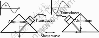
Fig.1 Schematic mechanism and signal splitter for generating shear waves
A wedge was fabricated from aluminum such that the cross section consists of an isosceles triangle with two 45?. It was necessary to keep the cases insulated from each other because the transducer cases are normally grounded and changed the polarity of one transducer to change this condition. The system was assembled for experimental acquisition of data by firstly placing the test specimen face down on the transmitter face plate and aligning its 90? axis between two transducers as shown in Fig.2(a). Fig.2(b) shows a photo developed to evaluate error layup of composite laminate. A 1 MHz shear wave transducer (Panametrics Co.) was connected to the receiver jack. Especially, the signal was at a maximum when the shear transducer was oriented parallel to this axis.
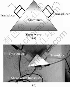
Fig.2 Conceptual sketch for measurement and jig for generating shear waves: (a) System was assembled for experimental acquisition of data by first placing the test specimen face down on the transmitter face plate and aligning its 90? axis between two transducers; (b) Photo developed to evaluate error layup of composite laminate
3 Results and discussion
3.1 Relationship between experimental and modeling solutions
Simulation was firstly made in order to confirm the generation of ultrasonic shear wave on the pyramid- shaped aluminum ally. Experiments were performed on unidirectional specimens fabricated from 40 plies of graphite/epoxy prepreg sheets to verify the simplified ply-by-ply vector decomposition model.
To verify the reduced model worked at various transducer angles, the first set of experiments were performed using one specimen of 40 aligned plies. Fig.3 shows comparison results between the experimental signal and the modeling signal. The slight differences in amplitudes can be attributed to a change of couplant conditions and ply orientation errors due to some variation of random layups. This agreement between the experimental and modeled wave forms verifies the adequateness of the simplified model to some degree. It is found that peak positions are well agreed between experimental and modeling data. Also, a typically peak- to-peak amplitude was measured in through-transmission mode experimentation. Experimentation consists of performing a polar scan using a through transmission with the transducers in a crossed arrangement, that is, the receiver polarization is oriented at 90? to the polarization of the transmitter. When the fixture is assembled for experimental data acquisition by first placing the test specimen face down on the transmitter face plate and aligning its 0?-90? axis between two transducers, it is found that the result are very sensitive with an angle of 90? between the transmitter and receiver in the through- transmission method.

Fig.3 Comparison of modeling and experimental solution for typically peak-to-peak amplitude (1��Experimental; 2��Modeling)
Specimens A, B and C were compared to demonstrate the test��s capability and sensitivity in determining a misoriented ply or an unsymmetrical layup with the same base sequence as a symmetrical layup with the experimental and theoretical results. First of all, in the case of specimen A with unsymmetric layups, it is found that experimental and theoretical results are shown to agree qualitatively. Fig.4(a) shows comparison between experimental and theoretical results in the case of specimen B (no error sample) with symmetric layups and specimen C (error sample) with a single misoriented ply with an otherwise symmetric layup. It is found that there is good coincidence in the amplitude and angle between experimental and theoretical results. This was done for transmitter orientations from 0? to 360? in 5? increments. The results are shown in Fig.4(a) for comparing difference between test and model. Modeling results were obtained by implementing the simplified ply-by-ply vector decomposition model. A program was made to compute the reference signal coefficients for any transducer and ply orientations. These results show a good qualitative agreement between the experimental and modeling solutions. Fig.4(b) shows relationship between angle location and peak amplitude for both no error and error samples. A difference was observed between no error and error samples due to a ply error in CFRP composite laminates. Therefore, it is thought that shear wave ultrasonic signals are very sensitive in the fiber direction of CFRP laminates.
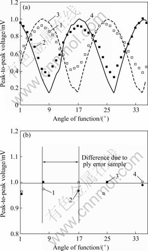
Fig.4 Modeling and experimental solutions for no error specimen B [(0/45/90/-45)5]S (a) and specimen C [(0/45/90/-45)5]S (b) (1��Experiment of no error sample; 2��Modeling of no error sample; 3��Experiment of error sample; 4��Modeling of error sample)
3.2 Simulation for generating shear wave
The simulation was performed with the numerical Wave-2000 Code (Cyber Logic. Co. Ltd.). A jig of pyramid-shaped aluminum alloy shown in Fig.5 is represented in the numerical model, including two ultrasonic transducers and jig. Approximately 12.7 mm in diameter for transducers were included in the model which was positioned on the 45?-skwed side of pyramid aluminum alloy. However, the trend of wave propagation can be observed in this model. The resolution of simulation is 1 MHz as shown in Fig.4. In Fig.5, wave propagations are displayed. Firstly, longitudinal wave is coming out from the transducer on the pyramid; in the mid area, this wave is supposed to propagate to the 45? direction, two ultrasonic waves meet at the bottom and eventually mode conversion occurs. Horizontal shear wave is generated at the bottom of pyramid-shaped aluminum alloy. So, it is found that there exists a good trend in the wave propagation between experimental and calculated results.
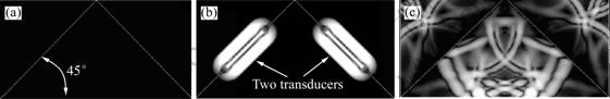
Fig.5 Simulation in order to generate shear wave on pyramid: (a) Pyramid drawing; (b) Ultrasonic wave generation; (c) Shear wave generation bottom
4 Conclusions
1) An experimental way is performed in order to make shear wave on the bottom of aluminum alloyed pyramid. A jig is manufactured and developed for generating a shear wave based on the computer numerical simulation.
2) Apyramid with an isosceles triangle with two 45? is made of aluminum to generate shear waves using two longitudinal transducers based on ultrasonic-polarized mechanism. It is found that shear wave can be generated at the bottom of aluminum-alloyed pyramid.
3) The shear wave ultrasonic technique is carried out in order to detect stacking orientation error for quasi-isotropy composite laminates.
4) Ultrasonic newly-generated shear wave is fairly sensitive to fiber direction of CFRP composite laminates. It is found that the experimentally shear wave behavior of newly-designed jig is consistent with simulated result on the bottom of pyramid for detecting the defects in CFRP composites.
References
[1] FEI D, HSU D K. Ultrasonically mapping the ply layup of composite laminate[J]. Mat Eval, 2002, 60: 1099-1109.
[2] FEI D, HSU D K, WARCHOL M. Simultaneous velocity, thickness and profile imaging by ultrasonic scan[J]. Journal of NDE, 2002, 20(3): 95-112.
[3] FEI D, HSU D K, LIU Z. Fiber orientation study using ultrasonic c-scan of ply interfaces[J]. Rev of Prog in Quantitative NDE, 2002, 21: 1070-1077.
[4] LIU Z, FEI D, HSU D K, DAYAL V, HALE E. Ultrasonic NDE and mechanical testing of fiber placement composites[J]. Rev of Prog in Quantitative NDE, 2002, 21: 1078-1085.
[5] IM K H, PARK N S, HSU D K, KIM S K, PARK J W, YANG I Y. Characteristic evaluation of CRRP composites under falling weight impact loading[J]. Rev of Prog in Quantitative NDE, 2002, 21: 1046-1053.
[6] FEI D, HSU D K. Interaction of shear wave with fiber orientation in composite laminate: Model and experiment[J]. Adv Com Mater, 2002, 11(1): 61-69.
[7] IM K H, KIM S K, YANG I Y. Impact damage and hygrothermal effects on fatigue bending strength of orthotropy composite laminates[J]. KSME International Journal, 1999, 13(7): 524-535.
[8] HSU D K, MARGETAN F J. Examining CFRP laminate layup with contact-mode ultrasonic measurements[J]. Adv Comp Lett, 1993, 2(2): 51-55.
[9] HSU D K. Material properties characterization for composites using ultrasonic methods[J]. Proceeding of Noise-Con, 1993, 94: 821-830.
[10] TIPPLER P A. Physics[M]. 2nd ed. New York, 1982: 863.
[11] URABE K, YOMODA S. Nondestructive testing method of fiber orientation in fiber reinforced composites by microwave[J]. Bulletin of Industrial Products Research Institute, 1987, 107: 11-21.
[12] URABE K, YOMODA S. Non-Destructive testing method of fiber orientation and fiber content in FRP using microwave[J]. Progress in Science and Engineering of Composites, 1982, 1(1): 1543-1550.
[13] FISHER B, HSU D K. A novel technique for characterizing shear wave ultrasonic transducers[J]. Review of Progress in QNDE, 1996, 15: 1191.
Corresponding author: Kwang-Hee IM; Tel: +82-63-290-1473; E-mail: khim@core.woosuk.ac.kr
(Edited by CHEN Can-hua)
