
Trans. Nonferrous Met. Soc. China 24(2014) s20-s28
Nonlinear buckling finite element analysis of stiffened B-Al plates
Ezgi GUNAY1, Cevdet AYGUN1, Yunus Onur YILDIZ2
1. Mechanical Engineering Department, Gazi University, Ankara 06570, Turkey;
2. Mechanical Engineering Department,  University,
  23119, Turkey
Received 18 June 2013; accepted 8 November 2013
Abstract:
Nonlinear buckling behavior of stiffened composite B-Al plates was analyzed by means of finite element analysis (FEA) method. In the method, the composite material was taken as B matrix into which Al fibers were embedded in different configurations. The laminated B-Al material in the form of rectangular plates was subjected to lateral compressive loading. It is observed that stiffeners have significant effect on the buckling behavior of plates under compressive loading and for various geometrical configurations. The stiffeners used in the modeling are one-sided and have rectangular cross-sections. It is found that there are physically important loading intervals and the critical buckling modes make transitions back and forth between stable and unstable states. Bifurcation buckling regions resulting from various configurations of fiber orientations and different plate aspect ratios are determined. The whole analysis is performed by using ANSYS finite element computations. Only the buckling patterns of stiffened plate configurations under simply supported boundary conditions are studied. Distributions of compressive stresses (��x) vs in-plane contractions (u) and compressive stresses (��x) vs out-of plane deflections (��) are obtained. Nonlinear analysis of the C2 fiber configuration yields the safest critical buckling stress amongst C1, C2, C3 and C4 configurations. It is concluded that FEA method for the nonlinear buckling analysis generates accurate results.
Key words:
nonlinear buckling; stiffener; composite plate; bifurcation; FEM modeling;
1 Introduction
Stiffened composite plates and shells that are strengthened with various supporting elements are used for the structural parts of ships, boats, aircraft, and satellite panels. Additionally, their increasing use is foreseen for many diverse applications such as sporting goods, new aerospace components, and new generation of automobiles. Because of their high strength, lightweight, and ease of use for production, stiffened composite plates are particularly suitable for critical structures, which require high specific strength. Studies show that stiffeners have significant effect on the buckling behavior of plates under various loading conditions and for different geometrical configurations. The determination of critical buckling loads in conjunction with the corresponding buckling modes for thin composite plates is one of the major problems in structural engineering.
Development of an effective method to calculate the strength of a plate, the stiffness of which was increased by adding stiffeners, was first conceived during the early ages (1920s) of the analyses of aircraft structures. TIMOSHENKO [1] suggested that the stiffness of a one-sided stiffener might be taken into account by replacing the moment of inertia of the stiffener about its center of gravity by an effective moment of inertia, and this value was used in the solutions valid for stiffeners with their centers of gravity located in the midplane of the plate. In this sense, usage of analytical methods to validate is cited by TIMOSHENKO [2] for dealing with problems of linear buckling analyses.
HU et al [3] used the analytical methods to analyze the nonlinear buckling. For this purpose, a theoretical study was undertaken on the behavior of simply supported square plates under compression, and the effect of the small deviations from flatness on effective width and buckling of plane was evaluated. SEIDE [4] calculated the effect of longitudinal stiffeners located on one side of a plate under the compressive buckling stress of the plate-stiffener combination. KUMAR and MUKHOPADHYAY [5] used finite element method for buckling analysis of laminated stiffened plates. PAIK and KIM [6] formulated the ultimate strength applicable to stiffened panels and their buckling modes under combined axial load, in-plane bending and lateral pressure. GUO et al [7] worked on the buckling behavior of stiffened laminated plates. BYKLUM and AMDAHL [8] developed the computational models using semi-analytical procedures. To this effect, a simplified method was used to calculate elastic large deflection of plates and stiffened panels. In this simplified method, local buckling formulations were analytically derived from energy equations. In a separate study, semi-analytical models were used for global buckling and post-buckling analysis of stiffened panels [9]. MALLELA and UPADHYAY [10] used the finite element method in a parametric study to calculate the buckling of laminated composite stiffened panels subjected to in-plane shear. GHANNADPOUR and ALINIA [11] used FEA method to work on the large deflection behavior of functionally graded square plates. The results were in accordance with the solutions presented by TIMOSHENKO and WOINOWSKY- KRIEGER [12]. ALINIA and DASTFAN [13] worked on the post-buckling capacity, deformability, energy dissipation and the cyclic behavior of stiffened and unstiffened panels under shear. It was concluded that an optimum amount of stiffeners was needed to achieve both sufficient rigidity and deformability. ALINIA and MOOSAVI [14] studied the buckling of web panels and their longitudinal stiffeners. YILDIZ [15] analyzed the linear and nonlinear buckling of stiffened steel and composite plates under axial loading by using ANSYS. Critical buckling loads and corresponding modes were solved and compared. SANAL and GUNAY [16] analyzed buckling of transversely stiffened rectangular composite thin plates under shear by using FEA method. ALINIA et al [17] worked on the nonlinear postbuckling behavior of thin shear panels, emphasizing on an intermediate limit state when panels experience first yield points and the growth pattern of yield zone. STAMATELOS et al [18] presented a methodology for making an analytical assessment of local buckling and post-buckling behavior of orthotropic stiffened plates. The approach considered the stiffened panel segment located between two stiffeners, while the remaining panel was replaced by equivalent transverse and rotational springs of varying stiffness, which acted as elastic edge supports. More recently, YAN et al [19,20] solved the critical buckling load of the stiffeners in press bend forming process. They modeled a special simulation procedure and a new calculation method of the punch and die boundary conditions based on the bending line positions was proposed. Stress and strain distributions were analyzed, and the deformation mechanics of the process was revealed.
In the current study, the rectangular cross-sectioned composite stiffeners were used on one surface of the composite plates. The loading type was compressive and applied through the lateral sides of the plate in order to simulate locally and globally buckled plates. Under these conditions, finite element method (FEM) was introduced for different aspect ratios, ��. The aspect ratio is defined as the ratio of the length of the plate to the width. By using the FEM and the corresponding nonlinear solutions, the critical buckling stresses ��cr, critical buckling strains ��cr, and out-of plane maximum deflections ��max for different buckling modes, and compressive stresses under stepwise incremental ��x were demonstrated. Critical buckling stresses ��cr and bifurcation critical points were determined and explained according to the number of rectangular cross sectional stiffeners and the orientation of the fibers in both the laminated plates and stiffeners.
2 Modeling
2.1 Finite element modeling of fiber composite stiffened plates
Buckling analyses of simply supported thin plates under compressive load are performed by employing shell mesh element SHELL91 (ANSYS). The element is defined by eight nodes, layer thicknesses, layer material direction angles, and orthotropic material properties. It has six degrees of freedom at each node [15]. A segment of plate is defined by the length a, width b, and thickness t, as shown in Fig. 1. Two, three and four sub-segments are designed from one segment by dividing it by one, two or three stiffeners, respectively. The width and the height of the solid rectangular stiffener are denoted by ts and h, respectively.
The aspect ratio (a/b) and slenderness ratio (b/a) of the plate are denoted by �� and 1/��. The geometric properties of composite plates for 0.4��1/�ա�1 are listed in Table 1. The elasticity modulii parallel and perpendicular to the fiber direction are E1=227 GPa and E2=139 GPa, respectively, and the shear modulii of materials in the 1-2 and 2-3 planes are G12=57.6 GPa and G23=49.1 GPa, respectively. Additionally, the Poisson ratios of the materials in the 1-2 and 2-3 planes are v12=0.24 and v23=0.36, respectively. K and Pcr denote the buckling coefficients and critical buckling load, respectively.
Rectangular cross-section stiffeners are used on the one surface of the plates, which are called single sided stiffeners throughout the remaining text. The composite material is made up of Boron matrix, and Al fibers are embedded into the matrix material. Such structures are named as metal matrix composites (MMCs).

Fig. 1 Geometrical arrangements of rectangular cross-section stiffeners on plates
Table 1 Geometric properties of laminated composite plates and their stiffeners

Geometrical ratio of the composite plate is defined as the ratio of the length of the plate to its thickness (a/t). Geometrical ratios are respectively selected as 25, 100, 125, 166 and 250, as listed in Table 1. Fiber configurations of the stiffened composite plates are denoted as C1 configuration [0��/90��/0��]plate+[(0��/ 90��)2]sstiffener, C2 configuration [0��/45��]plate+[(0��/ 45��)2]sstiffener, C3 configuration [(0��/45��)2]plate+[(0��/ 45��)4]stiffener, and C4 configuration [(0��/30��/45��/60��)2]plate+ [(0��/30��/45��/60��)2]stiffener, as shown in Fig. 2. The alphanumerics 0R, 1R, 2R and 3R denote the unstiffened plate and the stiffened plates with one, two and three stiffeners, respectively.
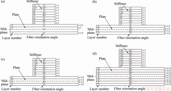
Fig. 2 Fiber orientations of C1 (a), C2 (b), C3 (c) and C4 (d) configurations
2.2 Numerical solutions
The basic task of this work is about to search for numerical solutions of the following Eq. (1), which is the mathematical formulation of buckling eigenvalue problem. Numerically calculated i-th eigenvalue (��i) from solution procedure yields critical buckling stresses related to the plate.
 (1)
(1)
where [KG], [M] and {��}i denote general geometric stiffness matrix, stress matrix and i-th eigenvector respectively.
The relationship between buckling coefficient (K) and aspect ratio (��) for simply supported boundary condition is given as
 (2)
(2)
Simply supported boundary conditions are illustrated in Fig. 3(a), and the compressive loading used on the singly stiffened composite plate is illustrated in Fig. 3(b) [15]. Unit loads are applied at the intermediate nodes as a total of two half loads whereas half loads are applied at the corner nodes.

Fig. 3 Characteristic specifications of analysis
The buckling analyses of the composite plates are made as follows. In the first stage of the solution, linear buckling analysis is started by applying unit displacements at the nodes located on the boundaries of the plate. At the end of this stage, the complete series of buckling modes are obtained. In order to analyze the buckled shape of the plate in terms of out-of plane deflections (��) in z-direction and in-plane contractions (u) in x-direction, nonlinear solution procedures are needed as a second stage solution. In the second stage of solution, the first buckling mode loading values are used to start the nonlinear buckling analyses. In this stage, the nodal displacements vector {U} is updated with the new displacement components. These new components are calculated by adding the first buckling mode shape values multiplied by 0.1% of the lateral nodal displacements {U} of the plate to the deflection values obtained from previous iteration. Nonlinear solution procedure is performed until twice the critical buckling load is attained. This critical buckling load is referred to as failure load in this work and in recent literature [9].
3 Results and discussion
Solution of compressive stresses (��x) vs in-plane contractions (u) is illustrated in Fig. 4. The (x, y) coordinates of locations of out-of plane maximum deflections on the plates for C1, C2, C3 and C4 configurations are calculated and indicated on the figures of compressive stresses (��x) vs out-of plane maximum deflection in z direction (��max). In Fig. 4, the critical stress markers available on the ��x axis denote calculated critical buckling stresses.

Fig. 4 Variations of ��x vs u for C1 type plates with dimensions of 200 cm��200 cm��2 cm
Figure 5 illustrates the variations of compressive stresses vs out-of plane maximum deflections for C1 configuration. As observed in Figs. 5(b)-(c), critical buckling stresses (��cr) are obtained as 79 MPa and 54 MPa for the plates with geometric ratios of 116 and 250, respectively. The unstiffened composite plates exhibit sharp bends of in-plane contractions between compressive stress (��x) values of 60 MPa and 80 MPa. In these figures, bifurcation regions clearly indicate the existence of unstable phenomena, which form sharp bends in out-of plane maximum deflection (��max).

Fig. 5 Variations of ��x vs ��max for C1 type plates with different dimensions
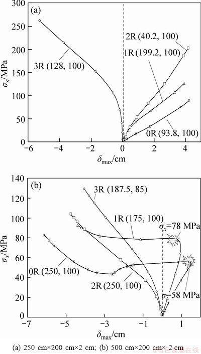
Fig. 6 Variations of ��x vs ��max for C2 type plates with different dimensions
Figure 6 demonstrates the buckling behaviour of different composite plates for C2 configuration by increasing the dimensions of the plate length, whereas the plate width remains the same. Figure 6(a) illustrates that the plate with 3R stiffeners warps toward the negative side of the midplane. In Fig. 6(b), because of longer plate length, the instability conditions emerge at smaller stress values of 58 MPa and 78 MPa for the 0R and 1R plates, respectively. In addition, the 3R-plate with geometric ratio of 166 with 3 stiffeners results in a convex (up) buckling shape but the other plates (0R, 1R and 2R) result in slightly convex (down) buckled plates in Fig. 6(b). Figure 7 demonstrates the buckling behaviour of various composite plates for C3 configuration by increasing the dimensions of the plate length whereas the plate width remains the same. Figure 7(b) illustrates that the plate with 3R stiffeners warps toward the negative side of the midplane. While the 3R-plate results in a convex (up) and unstiffened plate (0R) results in a convex (down) buckled shape in the negative deflection direction, remaining plates (1R and 2R) result in slightly convex buckled shapes. Because of the longer lengths of the plates, the instability condition emerges at smaller stress values of 72 MPa for the unstiffened plate. The same phenomenon appears in Fig. 7(c) at 40.63 MPa for the unstiffened plate with geometric ratio of 250. The transition or bifurcation region is that the applied stress is equal to the critical value. At this point, the plate is on the verge of unstable buckling stage. By adding a small increment to the compression loading, the plate makes a transition from stability to unstability. It assumes a buckled shape and at the same time loses its natural equilibrium. In this way, the plates collapse in negative z-direction. On the other hand, the 1R-plate remains stable in the positive z-direction.

Fig. 7 Variations of ��x vs ��max for C3 type plates with different dimensions
Figure 8 reflects the buckling behaviour of B-Al composite plates for C4 configuration. The rectangular plate with the geometric ratio of 166 is illustrated in Fig. 8(a). As the loading increases, the onset of bifurcation in 0R-plate at stress value of 60 MPa becomes noticeable. It is observed that the similar bifurcation behaviour is clearly visible in terms of out-of plane maximum deflection. The last rectangular plate with the geometric ratio of 250 is presented in Fig. 8(b). It displays the buckling modes for 0R-plate and 1R-plate for the case of geometric ratio of 250. As observed, the bifurcation behaviours for 0R-plate and 1R-plate occur at 41 MPa and 64 MPa, respectively.

Fig. 8 Variations of ��x vs ��max for C4 type plates with different dimensions
Figure 9 illustrates four different states of global buckling mode shapes, which are obtained during the initiation and progression course of the solution procedure as the compressive loading increases. Top and side views of each global buckling state are displayed separately in the same figure.

Fig. 9 Global buckled mode shapes of 500 cm��200 cm��2 cm unstiffened plate of C4 configuration
Figure 10 illustrates distributions of critical normalized buckling stress values vs slenderness ratios for multilayered fiber composite plates. Normalization is conducted by dividing critical normalized buckling stress values of 1R, 2R and 3R plates by critical normalized buckling stress values of 0R plates. Four different configurations C1, C1, C3 and C4 are used as varying parameters in the same figure to demonstrate the effects of fiber orientations. The critical buckling stress values increase as the number of stiffeners increases from one to three. Higher global buckling critical buckling stresses are observed in the composite plates with slenderness ratio of 1.4. The critical buckling stresses are normalized by dividing stresses of the stiffened plates by stresses of the unstiffened plates. It is observed that as the number of stiffeners increases, the plate is getting more stable. For the case of three stiffeners, C1 configuration displays more stable behavior than the C2 configuration and the C2 configuration exhibits more stable behavior than the other two configurations. This phenomenon can be explained by means of the effects of the bending- extension submatrix B in the stiffness matrix which is zero for both C1 and C2 configurations [21]. On the other hand, third column extensional stiffness submatrix [A] terms are all zero in C1 configuration, while these terms are non-zero in C2 configuration. These non-zero terms introduce the mid-plane strains to the constitutive equation. Thus, in-plane stress distributions become larger accordingly. Results obtained from Fourier series solutions [2, 4] and FEA buckling critical stress solutions of singly stiffened and simply supported square 300 cm��300 cm��1 cm steel plate (Est=210 GPa and vst=0.3) are presented in Table 2. The linear static analysis for the 3R square plates gives the critical buckling stresses in an order as 169.5 MPa (C1), 156.8 MPa (C2), 152.8 MPa (C3) and 151.2 MPa (C4). Nonlinear FE solutions of the same plates give the corresponding critical stresses as 193.5 MPa (C1), 203.8 MPa (C2), 200 MPa (C3) and 189.5 MPa (C4).
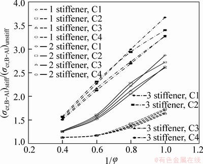
Fig. 10 Distributions of critical normalized buckling stress values vs slenderness ratios for plates with 1, 2 and 3 stiffeners
Table 2 Comparison of Fourier series and FEA buckling critical stress solutions of singly stiffened and simply supported square 300 cm��300 cm��1 cm steel plate (Est=210 GPa and vst=0.3)

4 Conclusions
1) The nonlinear analysis of the C2 configuration yields the safest buckling fiber orientations for stiffened plates.
2) The linear static analysis for the 3R square plates gives the critical buckling stresses in an order as 169.5 MPa (C1), 156.8 MPa (C2), 152.8 MPa (C3) and 151.2 MPa (C4). Nonlinear FE solutions of the same plates give the corresponding critical stresses as 193.5 MPa (C1), 203.8 MPa (C2), 200 MPa (C3) and 189.5 MPa (C4).
3) The rectangular cross-sectional stiffeners located parallel to the width of the plate cause stress concentrations in the adjacent sub-segments. The global buckling response of plates turns into a local buckling response as the plates are increasingly strengthened with stiffeners one by one. The global buckling phenomenon develops solely in square plates.
4) For 0R and 1R plates, transitions from stable to unstable state and back to stable state are caused by bifurcation regions.
Acknowledgements
In this work, use of ANSYS is officially endorsed by FIGES Company of Turkey and we greatly appreciate the support of FIGES in course of this work.
Appendix

where  is the stiffness matrix, A is the extensional stiffness submatrix, B is the bending and extension coupling stiffness submatrix, and D is the bending stiffness submatrix

Plate: C1 configuration-fiber orientations [0o/90o]s

Stiffener: C1 configuration-fiber orientations [(0o/90o)2]s

Plate: C2 configuration-fiber orientations [0o/45o]s

Stiffener: C2 configuration-fiber orientations [(0o/45o)2]s

References
[1] TIMOSHENKO S P. On the stability of stiffened plates [R]. Washington DC: Navy Yard, 1935.
[2] TIMOSHENKO S. Theory of elastic stability [M]. New York: McGraw- Hill Book Co. Inc., 1936: 350-437.
[3] HU P C, LUNDQUIST E E, BATDORF S B. Effect of small deviations from flatness on effective width and buckling of plates in compression [R]. Langley Field, Virginia: Langley Aeronautical Memorial Laboratory, 1946.
[4] SEIDE P. The effect of longitudinal stiffeners located on one side of a plate on the compressive buckling stress of the plate-stiffener combination [R]. Langley Field, Virginia: Langley Aeronautical Memorial Laboratory, 1953.
[5] KUMAR S Y V, MUKHOPADHYAY M. A new finite element for buckling analysis of laminated stiffened plates [J]. Composite Structures, 1999, 46: 321-331.
[6] PAIK J K, KIM B J. Ultimate strength formulations for stiffened panels under combined axial load, in-plane bending and lateral pressure [J]. Thin-Walled Structures, 2002, 40(1): 45-83.
[7] GUO M W, HARIK I E, REN W X. Buckling behavior of stiffened laminated plates [J]. International Journal of Solids and Structures 2002, 39: 3039-3055.
[8] BYKLUM E, AMDAHL J. A simplified method for elastic large deflection analysis of plates and stiffened panels due to local buckling [J]. Thin-Walled Structures, 2002, 40: 925-953.
[9] BYKLUM E, STEEN E, AMDAHL J. A semi-analytical model for global buckling and postbuckling analysis of stiffened panels [J]. Thin-Walled Structures, 2004, 42: 701-717.
[10] MALLELA U K, UPADHYAY A. Buckling of laminated composite stiffened panels subjected to in-plane shear: A parametric study [J]. Thin-Walled Structures, 2006, 44: 354-361.
[11] GHANNADPOUR S A M, ALINIA M M. Large deflection behavior of functionally graded plates under pressure loads [J]. Composite Structures, 2006, 75: 67-71.
[12] TIMOSHENKO S, WOlNOWSKY-KRlEGER S. Theory of plates and shells [M]. New York: McGraw-Hill, 1959: 41-56.
[13] ALINIA M M, DASTFAN M. Cyclic behaviour, deformability and rigidity of stiffened steel shear panels [J]. Journal of Constructional Steel Research, 2007, 63: 554-563.
[14] ALINIA M M, MOOSAVI S H. A parametric study on the longitudinal stiffeners of web panels [J]. Thin-Walled Structures, 2008, 46: 1213-1223.
[15] YILDIZ Y O. Buckling analysis of stiffened composite plates with finite element method [D]. Gazi University, Ankara, 2007.
[16] SANAL O, GUNAY E. Finite element buckling analyses of transversely stiffened orthotropic rectangular thin plates under shear loads [J]. Journal of Reinforced Plastics and Composites, 2009, 28: 109-127.
[17] ALINIA M M, HABASHI H R, KHORRAM A. Nonlinearity in the postbuckling behaviour of thin steel shear panels [J]. Thin-Walled Structures, 2009, 47: 412-420.
[18] STAMATELOS D G, LABEAS G N, TSERPES K I. Analytical calculation of local buckling and post-buckling behaviour of isotropic and orthotropic stiffened panels [J]. Thin-Walled Structures, 2011, 49: 422-430.
[19] YAN Y, WANG H, WAN M. Prediction of stiffener buckling in press bend forming of integral panels [J]. Transactions of Nonferrous Metals Society of China, 2011, 21: 2459-2465.
[20] YAN Y, WANG H, WAN M. FEM modelling for press bend forming of doubly curved integrally stiffened aircraft panel [J]. Transactions of Metals Society of China, 2012, 22: 39-47.
[21] JONES R M. Mechanics of composite materials [M]. Philadelphia, USA: Taylor&Francis, Inc., 1999: 55-87, 187-201.
��-��ǿ����ķ�������������Ԫ����
Ezgi GUNAY1, Cevdet AYGUN1, Yunus Onur YILDIZ2
1. Mechanical Engineering Department, Gazi University, Ankara, Turkey;
2. Mechanical Engineering Department, University, , Turkey
ժ Ҫ��ͨ������Ԫ������FEA������ǿ�����ϰ�ķ�����������Ϊ����ģ������-�����ϲ�����������Ƕ�����еIJ�ͬ��̬��Al��ά��ɡ���Ƭ��ṹ��B-Al���ΰ�ʩ�Ӻ���ѹ��Ӧ��������ǿ����ά�Ծ��в�ͬ������״��ĵ�������Ϊ������Ӱ�졣��ģ�в��õ����о��ν����ǿ����ά��������������ع����д���һ��Ҫ���غɷ�Χ���ٽ�����ģʽ����̬�ͷ���̬֮�䷴��ת�䡣ȷ���ɲ�ͬ����ά��̬�Ͱ�ĸ߿�����ɵķֲ�ʧ������ͨ��ANSYS����Ԫ���㣬�о���֧�߽�������ǿ����ĵ�ʧ��ģʽ���ֱ�õ�ѹӦ��(��x)��ƽ������(u)�Լ�ѹӦ��(��x)�������Ӷ�(��)�Ĺ�ϵ���ߡ�ͨ�������Է�������C1�� C2�� C3 �� C4 ������̬����ά�У�Ƕ��C2��ά�İ�Ļ���ȫ���ٽ�����Ӧ�������������FEA�����������������Եõ���ȷ�Ľ����
�ؼ��ʣ���������������ǿ����ϰ壻�ֲ�ʧ�ȣ�����Ԫ��ģ
(Edited by Jing-hua FANG)
Corresponding author: Ezgi GUNAY; Tel: +90-312-582-3411; Fax: +90-312-230-8434; E-mail: egunay@gazi.edu.tr
DOI: 10.1016/S1003-6326(14)63283-0
Abstract: Nonlinear buckling behavior of stiffened composite B-Al plates was analyzed by means of finite element analysis (FEA) method. In the method, the composite material was taken as B matrix into which Al fibers were embedded in different configurations. The laminated B-Al material in the form of rectangular plates was subjected to lateral compressive loading. It is observed that stiffeners have significant effect on the buckling behavior of plates under compressive loading and for various geometrical configurations. The stiffeners used in the modeling are one-sided and have rectangular cross-sections. It is found that there are physically important loading intervals and the critical buckling modes make transitions back and forth between stable and unstable states. Bifurcation buckling regions resulting from various configurations of fiber orientations and different plate aspect ratios are determined. The whole analysis is performed by using ANSYS finite element computations. Only the buckling patterns of stiffened plate configurations under simply supported boundary conditions are studied. Distributions of compressive stresses (��x) vs in-plane contractions (u) and compressive stresses (��x) vs out-of plane deflections (��) are obtained. Nonlinear analysis of the C2 fiber configuration yields the safest critical buckling stress amongst C1, C2, C3 and C4 configurations. It is concluded that FEA method for the nonlinear buckling analysis generates accurate results.
