
J. Cent. South Univ. (2017) 24: 1866-1880
DOI: https://doi.org/10.1007/s11771-017-3594-6

Forming condition of transient saturated zone and its distribution in residual slope under rainfall conditions
ZENG Ling(����)1, 2, 3, BIAN Han-bing(�庺��)2, 3, SHI Zhen-ning(ʷ����)4, HE Zhong-ming(������)4
1. Engineering Laboratory of Spatial Information Technology of Highway Geological Disaster Early Warning in
Hunan Province, Changsha University of Science and Technology, Changsha 410114, China;
2. School of Civil Engineering and Architecture, Changsha University of Science & Technology,Changsha 410114, China;
3. LEM3 UMR CNRS 7239, University of Lorraine, Metz 57045, France;
4. School of Traffic and Transportation Engineering, Changsha University of Science & Technology,Changsha 410114, China
 Central South University Press and Springer-Verlag GmbH Germany 2017
Abstract:
Rainfall, as one of the most significant factors triggering the residual soil slope failure, leads to not only the reduction of soil shear strength, but also the increase of soil weight and the decrease of matric suction as well. All these modifications in soil properties have important influence on the slope stability. The water infiltration and redistribution inside the slope are the preconditions of the slope stability under rainfall conditions. Based on the numerical simulation via finite element method, the water infiltration process under rainfall conditions was studied in the present work. The emphases are the formation, distribution and dissipation of transient saturated zone. As for the calculation parameters, the SWCC and the saturated permeability have been determined by pressure plate test and variable head test respectively. The entire process (formation, development, dissipation) of the transient saturated zone was studied in detail. The variations of volumetric water content, matric suction and hydraulic gradient inside the slope, and the eventually raise of groundwater table were characterized and discussed, too. The results show that the major cause of the formation of transient saturated zone is ascribed to the fact that the exudation velocity of rainwater on the wetting front is less than the infiltration velocity of rainfall; as a result, the water content of the soil increases. On the other hand, the formation and extension of transient saturated zone have a close relationship with rainfall intensity and duration. The results can help the geotechnical engineers for the deeper understanding of the failure of residual slope under rainfall condition. It is also suggested that the proper drainage system in the slope may be the cost-effective slope failure mitigation method.
Key words:
1 Introduction
The site monitoring, numerical simulations and theoretical researches indicate that the slope failure is of relevance to one or more factors, such as hydrogeology, climate, soil properties and artificial slope cutting [1]. In China, nearly 90% landslide disasters have been directly or indirectly induced by atmospheric precipitation. Apparently, rainfall has become the governing factor triggering landslides and consequent shallow failures. With the rapid development of Chinese highway and railway network in recent years, lots of artificial cutting slopes have appeared and exposed to the rainfall conditions. The rainfall infiltration will increase soil water content and the rise of phreatic surface. As a result, the shear strength and the matrix suction of the slope soil will decrease. Consequently, the probability of the slope instability increases [2-4]. In order to insure the stability of this kind of slopes, the geotechnical engineers and slope constructers usually take conservative measures for the slope protection, which results to a big economic waste. It is of great interest to understand the failure process of the slope due to rainfall and to find a cost-effective mitigation method.
The stability of residual slope depends on the soil properties, especially the soil strength which is associated with the state of stresses and water content in the soil. Generally, the rainwater infiltration has a negative impact on the stability: the soil strength drops and its weight increases. In such case, the soil should be considered as tri-phasic material and the unsaturated soil mechanic should be used. As suggested by FENG and FREDLUND [5], HO and FREDLUND [6], the unsaturated shear strength has considered not only the effective shear strength but also the matric suction. However, under the rainfall infiltration, the change of soil volumetric mass, which has been considered as the external loads, is also an important factor for the slope stability. In fact, the distribution and variation of the matric suction, the volumetric mass and the effective shear strength all depend on the water content in the soil. The most intuitive way to characterize the water content in the residual soil is to investigate the wetting front (the boundary between the areas affected and non-affected by rainfall infiltration) by either the in-situ investigation or the numerical simulation. Meanwhile, it is essential to analyze the variation laws of pore water pressures and hydraulic gradient in the slope [7, 8]. However, the distribution and the variation of water content in a residual slope are controlled by many factors including the soil properties, the slope angle and the hydraulic conductivity. The position of wetting front and its penetration velocity closely depend on the rainfall intensity. It is generally recognized that the water content (The water content, unless otherwise precision, is volumetric water content) behind the wetting front is greater than its initial state and even saturated. After the stop of rainfall, the wetting front disappeared with the rainwater exudation. Therefore, the transient saturated zone can be defined as the saturated zone during the rainfall process [9].
With saturated states, the soil in the residual slope attends its minimum values of many mechanical properties, such as the shear strength, the cohesion and the matric suction, etc. The saturation also distinguishes two totally different soil mechanics: the classic soil mechanics generally applied for the saturated or dry soil [10] and the unsaturated soils mechanics were suitable for the unsaturated soils [11]. It is well known that the volumetric mass of soil increases with water content and attends its maximum value when saturated. Hence, it is of great interesting to investigate formation, transition and distribution of transient saturated zone under rainfall conditions. Until now, in the literature, the slope stability affected by rainfall has been focused on the following three aspects. The first one concerning the soil-water characteristic curves (SWCC) of the slope soil, many researches have been conducted experimentally. In these experiments, the initial density, the gradation and the stress levels are the main factors considered. For example, MILLER et al [12] studied the impact of both soil types and compressibility on the SWCC; SUGJII et al [13] investigated the relationship between SWCC and the initial porosity of different soils. The second one concerns the slope seepage characteristic under rainfall infiltration. These researches conducted by either the in-situ/laboratory experiments or numerical simulations. The main objectives are the determination and the calibration of the in-situ seepage parameters in the residual slope. With these obtained results, the infiltration of rainwater has been estimated and the impacts of rainfall on the shear strength were analyzed. For example, CUOMO and DELLA[14] pointed out that the shallow slope runoff generation mechanism and the quantity of runoff are controlled by multiple factors which are tightly associated with the seepage process of rain water. DOU et al [15] showed that the soil seepage parameters have an important impact on the slope stability via the rainwater infiltration process. The third one concerns the application of the unsaturated shear strength theory on the slope stability based on the seepage analysis results. For example, considering the deterioration of soil strength due to rainfall infiltration, the depth of shallow landslide is predicted by OH and NING [16].
According to the existing literature, lots of the numerical simulations considered only the fluctuation of phreatic surface on the slope stability. And for the sake of simplification, it is supposed that the pore water pressure on the failure surface is 0 kPa or sometime greater than 0 kPa [17-19]. However, according to recent in-situ observations and experiment data, the mentioned hypotheses used in the literatures are not true [20]. The pore water pressure on the slip surface is not, as traditionally supposed, 0 kPa but smaller than 0 kPa [21]. Thus, certain remediation should be made for the improvement in the residual slope stability analysis under the rainfall conditions. Studies also point out that the residual soil slope failures are usually shallow landslide. And the slip surface is located either in saturated zone or unsaturated zone below the transient saturated zone [22].
Consequently, the numerical studies in the literature underestimated the impact of seepage condition above groundwater table on the slope stability and especially the impact of the increase of soil weight in transient saturated zone on the slope stability. All these indicate that the formation, the development and the dissipation of the transient saturated zone in the residual slope have an important influence on the slope stability. Thus, it is of great interest to study the transient saturated zone and its impact on the slope stability under rainfall condition. The governing equations for the rainwater infiltration process in the residual slope are briefly presented after the general introduction. Then, the numerical model, as well as its parameters is given, the numerical results, firstly for the 1D infiltration model and the 2D infiltration model of a typical residual slope, are discussed. After the validation and clarification of the calculation model, a typical excavated residual slope has been analyzed and several remarks are given. The article is terminated with several general conclusions for the residual slope under rainfall conditions.
2 Governing equations for saturated- unsaturated seepage in residual slope
The rainwater infiltration process inside the residual slope is generally 3D problem. During the rainfall events, the seepage conditions at the slope surface were changed with time. It is a typical unsteady seepage process. Frequently, the soil in the residual slope above the phreatic surface should be considered as unsaturated soil. So, the saturated and unsaturated 3D unsteady seepage equations are necessary for the seepage study during and after rainfall process.
2.1 Darcy��s law for unsaturated soils
Initially, the Darcy��s law has been used for the description of the water flow in saturated soil. In such case, only one liquid, the water occupies the pores. While in case of unsaturated soil, as pore water and pore air coexist in the pores, the seepage process is generally a two-phase flow problem with different flow properties. The Darcy��s law should be extended to take into consideration of the variations of hydraulic conductivity of each phase in function of water content. With the decrease of water content, the hydraulic conductivity for pore water decreases sharply and the conductivity for pore air increases. As our researches focus on the transition saturated zone, the flux of air is less important and can be neglected here. Thus, the generalized Darcy��s law for the residual slope soil reads as follows [23]:
 (1)
(1)
where vw is the pore water flux; kws is the intrinsic permeability in saturated case and kw(��w) is the relative permeability with respect to the water content; �� represents the dynamic viscosity of pore water; ��w is the volumetric mass of pore water and g is the gravitational acceleration. h is the hydraulic head or total head including two parts as h=hw+z where z is elevation head, and it is considered reference. hw is the pressure head represents the pressure potential in saturated case and matric potential in unsaturated case. ��w is the water content in soil.
2.2 Mass conservation and governing equation
The mass conservation equation or the continuity equation is given as [24]
 (2)
(2)
The left part of the equation above means the variation of the storage of pore water for a given representative elementary volume (REV) of unsaturated soil. The divergence operator represents the difference between the in and out flux of the given REV. The last term in the equation, W, represents the source.
Substituting Eq. (1) into Eq. (2), the governing equation for the 3D seepage problem could be given as
 (3)
(3)
This is a second order partial differential equations which governing the seepage process. This equation could not be resolved only when the relationship between the water content and the pore water pressure could be established for the unsaturated soil.
In fact, two different approaches could be distinguished in the mechanics of unsaturated soil: the concept of the effectives stress initially proposed by TERZAGHI and PECK [25] and then developed by BISHOP and HENKEL [26]; and that proposed by FREDLUND [27] and ALONSO et al [28], two independent state variables are used. In our research the last concept was adopted. The two independent stress state variables (��-ua) and (ua-uw) are used to define state of stresses in the unsaturated residual soil, �� represents the total stress, while ua and uw represent the pore air pressure and pore water pressure respectively. It is assumed that the change of water content is due to the variation of (��-ua) and (ua-uw) as
 (4)
(4)
where m1w is the coefficient of water content change with respect to the means stress (��-ua), while coefficient m2w is the specific water capacity. It is evident that in the saturated zone m2w equals 0. In the unsaturated zone, the hydraulic conductivity and m2w are functions of the matric suction (ua-uw).
For the residual slope, the external load �� is constant. As the pore air is connected to the atmosphere, the pore air pressure is also constant. Thus the first term in the right part of Eq. (4), d(��-ua) is zero. Substituting Eq. (4) into Eq. (3) by consideration the relation following:
 (5)
(5)
After the mathematic manipulation, we get the governing equation of seepage applicable for both or saturated and unsaturated soil as follows:
 (6)
(6)
In the governing equation, the water head h has been chosen as the unknown variables. This equation could not be solved only the initial conditions, the boundary conditions and the relation between the water content and water head (SWCC) are known.
2.3 Soil-water characteristic curve (SWCC) of residual slope soil
In the above equation, kw is the relative permeability which is in function of the water content has to be determined before the numerical simulations. However, this relation is very difficult to get experimentally. In fact, during the experiment, the water content and the flow should be controlled simultaneously. In the literature, the relative permeability is generally obtained by the Soil-water characteristic curve (SWCC) [29, 30]. Due to the simple form, the formulation of van GENUCHTEN [30] has been adopted in current numerical simulation, as
 (7)
(7)
As consequence, the relative permeability can be given as
 (8)
(8)
where �� is an empirical parameter (kPa-1) whose reciprocal value can be assumed as the air entry value (kPa); n and m are fitting constants reflecting the slope of the water content-suction curve.
According to its hydro-mechanical properties, the residual soil can be considered as saturated as the water saturation greater than 90% [31]. This can be augured as: 1) physically, the soil is difficult to completely saturate due to air presented in the soil; 2) When the saturation increased from 90% to 100%, the residual soil strength is almost the same; 3) From a security point of view, selecting the smaller water content as the standard for judging the zone of saturation can make the stability analysis result more secure. Therefore, if there is no special instructions, saturated refers to the saturation greater than 90%, while completely saturated refers to the saturation is 100%.
2.4 Numerical implementation
Frequently in the analysis of slope stability, the 2D model is used for the reason of simplicity. In fact, for the seepage analysis, the water flux in the slope are dominant, while that of out-plan is less interest and sometimes is negligible. So in our research, the 2D plan model has been adopted for the seepage analysis in the residual slope. Furthermore, as there is no source, and the permeability of the soil is different in the two global directions, the governing Eq. (6) could be simplified as
 (9)
(9)
In fact, Eq. (9) is a typical nonlinear boundary value problem and for its numerical implementation, the finite element method has been used. The water head and the water content have been chosen as field variables. The calculation domain, e.g. the residual slope has been discretized in numerous finite elements discretization. In our research the quadrilateral element has been used.
In the finite equation, the solution of finite element for a transient analysis is a function about {H} and t. The time integration can be performed by a finite difference approximation scheme. Writing the finite element equation in terms of finite differences leads to the following equation:

 (10)
(10)
where [K] is the element characteristic matrix, which is in function of the permeability and relative permeability; [M] is the element mass matrix, which is in function of the volumetric mass of water and dry soil; t is the time; �� is a ratio between 0 and 1 which corresponding to different integration schemes; H1 is the water head at the end of time increment; H0 is the water head at start of time increment; Q1 is the nodal flux at end of time increment and Q0 is the nodal flux at start of time increment.
As indicated by Eq. (10), in order to figure out the new water head at the end of the time increment, it is necessary to know the water head at the start of increment. Stated in general terms, the initial conditions must be known in order to perform a transient analysis. The boundary conditions are given as [25]
 (11)
(11)
 (12)
(12)
where ht total head at node; S1 is head boundary and S2 is flux boundary; q(x, y, t) the prescribed flux at the boundary S2; and n is normal direction of boundary surface of S2. And i is the limit of soil absorption capacity, which is tightly related with the soil permeability and water content. When the prescribed boundary flux is greater than the limit i, the imposed rainwater does not fully enter the soil but with a runoff at the surface. To allowing the runoff, the boundary condition is then transformed into a head-type with H equal to the y-coordinate (zero water pressure for suction).
While for the initial condition, a steady-state seepage flow calculation should be done with the initial boundary conditions given by Eq. (11), and the results are served as the initial boundary conditions. Then in case of rainfall, the flux boundary is set as Eq. (12) with the potential possible of runoff. It is worth mentioning here, the porosity and the soil storage capacity are assumed to be constants in the proposed approach. Generally, the variation of the water content (or the matric suction) may result in residual deformation, and then cause the change of porosity. For a residual slope which has already existed for a long period and subjected or many cyclic variation in water content, the porosity could be supposed as already stable. The influence of such hypothesis will be analyzed in another full coupled analysis. Theoretically, the suction in the soil could be as large as infinite. However, taking the factors of water evaporation, the maximum negative pore water pressure is taken as -150 kPa in the following numerical simulations for the rainfall infiltration [25].
3 Numerical models and parameters
3.1 Numerical model and hydraulic boundary conditions for rainfall seepage analysis
To investigate the formation, development and dissipation of the transient saturated zone in the residual soil slope under rainfall conditions, the governing equation proposed in the section precedent has been implemented in a finite element calculation code and used for the seepage analysis. As indicated in section 2, the infiltration of rainwater within the slope is mainly controlled by the initial water content and the intrinsic permeability. As the soil is generally the anisotropic material, two permeability kwx and kwy are generally need respectively in the two local direction x and y (corresponding to the soil surface). Moreover, the incline angle of the slope also has an important influence on the rainfall infiltration process. For clarifying the impact of each factor, two numerical models have been employed. Firstly, the 1D infiltration process model (Fig. 1) has been used to analyze the formation condition of transient saturated zone. In this case, the rainwater flux in other directions as well as the incline angle of slope has been neglected. Then, an ideal 2D slope model (Fig. 2) is used to study the distribution law of transient saturated zone affected by both kwx and kwy. In these numerical models, the rainfall intensity is transformed as the flux boundary and applied on the surface of the model as shown in Figs. 1 and 2. In the 1D model, the thickness of silty clay and bedrock are 6 m and 2 m, respectively. The phreatic surface is located at the interface between silty clay and bedrock. While for the 2D slope model, the thickness of silty clay is 3 m and bedrock ranges from 2-9 m as illustrated in Fig. 2. And the phreatic surface locates at the soil/rock interface. In both two models, the quadrilateral element has been used. The space discretization has been illustrated in Figs. 1 and 2. There are 400 elements and 451 nodes in the 1D model, while 1378 elements and 1445 nodes in 2D model.
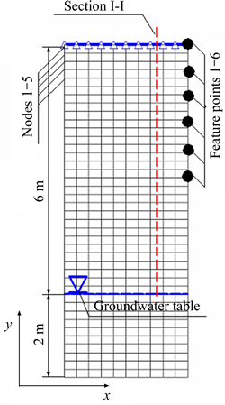
Fig. 1 Numerical model for 1D seepage analysis
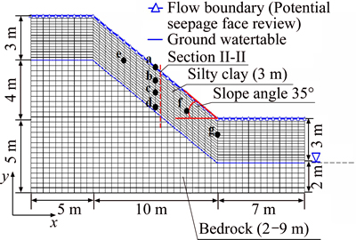
Fig. 2 Numerical model for 2D seepage analysis
In the 1D and 2D models (see Figs. 1 and 2), the feature points 1-6 and points a-g are located on the right of the 1D model and in the middle of the 2D model. For analyzing the formation process of transient saturated zone, the feature points 1-6 with coordinates (3, 6), (3, 5.6), (3, 5.2), (3, 4.8), (3, 4.4) and (3, 4) have been plotted on the 1D model. At the same time, the coordinates of feature points a-g is: a(10.4, 8.1), b(10,4, 7.1), c(10.4, 6.1), d(10.4, 5.1), e(8.5, 8.5), f(12.5, 5.6) and g(15.0, 3.9). The section I-I and section II-II are used to analyze the distribution of water content and pore water pressure along the elevation. The nodes 1-5, located on the left of 1D model, are used to analyze the relationship between rainfall infiltration velocity and water content.
The geometry size is shown in Figs. 1 and 2. At the right and left boundaries, there was no flux above the groundwater table. The parts below the groundwater table were assumed to be constant head boundary. The bottom boundary was assumed to be a no-flow boundary. Rainfall intensity was applied along the model surface as boundary conditions.
3.2 Model parameters
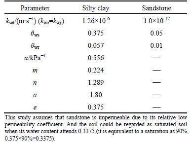
As the slope soils in different depths have different levels of weathering and suffers different levels of compaction during the formation history, the permeability at different depths are different. This has already be confirmed by the in-situ observation.Furthermore, the saturation or the water content has also important nonlinear impact on the relative permeability. In place of the direct laboratory test for the relative permeability determination, the SWCC has been determined firstly by the pressure plate test on the remold specimens (Fig. 3). And then, the relative permeability for unsaturated soil could be obtained from Eq. (8) proposed by van GENUCHTEN [30]. The permeability for full saturated specimen was measured in the laboratory via the falling head permeability test. The essential parameters for the numerical calculation are listed in Table 1.
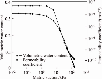
Fig. 3 Soil-water characteristic curve and permeability coefficient in function of matric suction for residual soil
For clarifying the influence of different factors on the transition saturated zone under rainfall condition, the parametric analysis has been done for both of twomodels. The calculation cases are listed in Table 2. From Table 2, it can be seen that the 1D seepage model is mainly focused on the formation of transient saturated zone due to rainfall intensity. For this case, two calculations schemes have been considered. Scheme 1 mainly used to analyze the formation mechanical characteristics of transient saturated zone and the correlation between formation of transient saturated zone and rainfall intensity. While for the scheme 2, it is mainly used to study the impact of both rainfall intensity and permeability on the extension of transient saturated zone. The 2D model studies the impact of rainfall intensity and duration on the formation and distribution of transient saturated zone. In this case, only one scheme has been considered, it is mainly used to analyze the distribution and extension of transient saturated zone in different rainfall intensity condition. For the reason of simplification, the maximum value of the matric suction is limited as -150 kPa. At the soil/atmosphere interface, the maximum soil suction has also been taken as the initial boundary conditions.
Table 1 Essential model parameters for seepage analysis
4 Results of discussions
4.1 1D seepage analysis
The two rainfall conditions for the 1D model listed in Table 2 are as follows: 1) the rainfall intensity begins from 2.0��10-7 m��s-1 to 8.0��10-7 m��s-1 with the step of ��q=1.0��10-7 m��s-1. There are totally 7 calculations; 2) the rainfall begins from 1.0��10-6 m��s-1 to 1.5��10-6 m��s-1 with the step of ��q=0.1��10-6 m��s-1. There are totally 6 calculations. These rainfall intensities have been served as the flux boundary conditions for the 1D model. Firstly, the distribution of water content in section I-I at the moment when the rainfall is stopped (24 h) is given in Fig. 4. It can be seen that the water content of soil is increased for all the calculations in scheme 1. However, the affected depth seems to be proportional with the rainfall intensity. Additionally, the closer to the surface, the greater the water content��s increase is. In the rainfall infiltration distributed zone, the increase rate of water content is inversely proportional to the depth. As for different rainfall intensities, the rainfall infiltration distributed depth increases with the rainfall intensity. In this study, the soil could be regarded as saturated soil when its water content attends 0.3375 which equivalents to 90% saturation (this has been discussed in section 2.3). According to this criterion, as illustrated in Fig. 4, the right side of the dotted line is saturated region and it is unsaturated region on the left. However, the saturated zone does not appear for all the calculation cases in scheme 1. Only the cases with the rainfall intensity greater than 4.0��10-7 m��s-1 has the transient saturated zone after 24 h of rainfall. It is worth noticing that the extension of saturated zone is always smaller than the infiltration depth for all the rainfall intensities used. The infiltration of rainwater induces not only the increase of water content but also the augmentation of pore water pressures. The distribution of pore water pressures is given in Fig. 5. The infiltration depth of rainwater and rainfall intensity show linear correlation while the water content of surface and rainfall intensity show logarithmic relationship as illustrated in Fig. 6. The results show that for a given duration, for example 24 h, the appearance of transient saturated zone depends on the rainfall intensity. The rainfall intensity for forming transient saturated zone need be greater than a rainfall threshold rather than ksat within the given rainfall duration. The threshold is related to the initial seepage condition or the intrinsic permeability.
Table 2 List of cases considered in parametric analysis
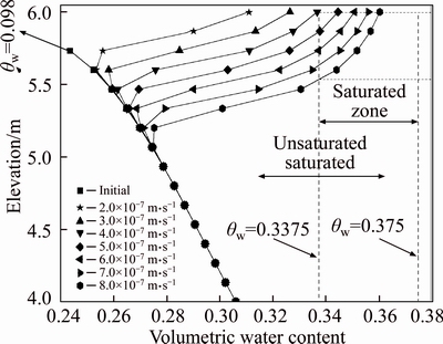
Fig. 4 Water content distribution along elevation of section I-I
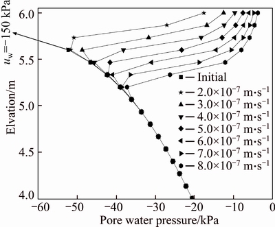
Fig. 5 Distribution of pore water pressures along elevation of section I-I (q=2.0��10-7 m��s-1-8.0��10-7 m��s-1 (��q=1.0��10-7 m��s-1))
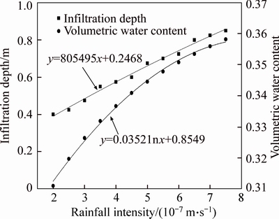
Fig. 6 Infiltration depth and surface water content under different rainfall intensities
For further study the formation of transient saturated zone, the rainfall duration is extended to 6 days in Scheme 1. Figure 7 displays the earliest time the transient saturated zone appears in different rainfall intensities. The relationship between time and rainfall intensity fits the function T=4��10-13q-2.1488. It seems that the formation of transient saturated zone depend not only the rainfall intensity but also the rainfall duration. If the rainfall duration is enough, the transient saturated zone could be formed with small rainfall intensity. Figure 8 shows the variation of water content at feature points 1-6 (Fig. 1) at the rainfall intensity of 8.0��10-7 m��s-1 (distribution of the feature points from top to bottom in order from 1 to 6). The water content increases from the initial condition. After the rainfall starts, the water content at feature point 1 increases gradually until saturated. At this moment, the water content at feature points 2 increases gradually until saturated, too. Both of the feature points 1 and 2 keep saturated until the stop of rainfall. This indicates that, once the transient saturated zone is formed, its extension will continuously increase or keep constant during the rainfall process. The variation of water content at feature points 3-6 is similar to feature points 1 and 2. It is worth mentioned that the water content of latter feature points starts to rise before the saturated of the previous feature points. This reveals that the rainwater infiltration is independent the formation of transient saturated zone. Figure 8 also shows that saturated zone is extended in the model from its surface to deeper one during rainfall process.
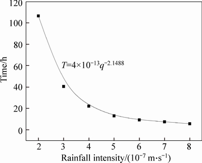
Fig. 7 Relationship between rainfall intensity and time of appeared transient saturated zone
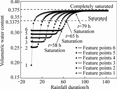
Fig. 8 Relationship between water content and duration of rainfall for different feature points
Figure 9 shows the water content and infiltration velocity at node 1-5 under the condition of rainfall intensity of 8.0��10-7 m��s-1. It can be seen that for node 1 which locates on the surface, the infiltration velocity overlaps with the exudation velocity curve. The velocity of node 1 sharply increases with the increase of water content. The velocity of node 1 starts to drop as the transient saturated zone appears on surface, but it is still greater than the nodes 2-5 during the rainfall. With the further infiltration, the nodes 2-5 become saturated one after another, indicating the extension of transient saturated zone. The nodes 1-5 reach saturated as its infiltration velocity reaches to its peak value. It is worth mentioning that the infiltration velocity at model surface is greater than exudation velocity below the transient saturated zone at any moment of the rainfall duration.
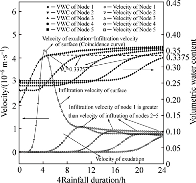
Fig. 9 Variation of water content and velocity at points 1-5 (Rainfall intensity: 8.0��10-7 m��s-1)
As given in Fig. 7, the rainfall duration for forming transient saturated zone is 5.5 h with the rainfall intensity as 8.0��10-7 m��s-1. Figure 10 shows the distribution of water content and the infiltration velocity in section I-I after 5.5 h rainfall. The infiltration velocity of wetting front (node 2) is 1.23��10-8 m��s-1 which is smaller than surface infiltration velocity (4.32��10-6 m��s-1). Statistically, the variations of water content and velocity in the Figs. 9 and 10 are applied to all designed rainfall cases in the present work.
It can be concluded that the extension of transient saturated zone is governed by both the rainfall intensity and its duration. Meanwhile, the intrinsic cause for the formation of transient saturated zone is the infiltration velocity at surface greater than exudation velocity at the wetting front. The forming and development of saturated zone can be described as follows. The water content at model surface increases and attends to its saturated state due to the rainwater infiltration. That is the initiation of the transient saturated zone. As the rainfall continues, the infiltration velocity at the upstream of the transient saturated zone greater than the extrusion velocity at the wetting front (the downstream), the transient saturated zone extends. Once the balance between the infiltration and extrusion is established, the transient saturated zone will be constant.
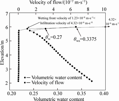
Fig. 10 Distribution of water content and velocity in section I-I (rainfall for 5.5 h, intensity of 8.0��10-7 m��s-1)
For deeper understanding the impact of rainfall on the formation, extension and dissipation of transient saturated zone, the second scheme 2 (Table 2) is performed. In this scheme, the greater rainfall intensity has been used. In this scheme, all the rainfall intensities lead to the formation of transient saturated zone. The distribution of water content and pore water pressures in different rainfall intensity is shown in Fig. 11. With the rainfall intensity ranging from 1.0��10-6 m��s-1 to 1.2�� 10-6 m��s-1, the water content at the model surface is greater than 0.3375 but not yet fully saturated and the pore water pressure is still negative. It can be seen that both the water content and pore water pressures increase with the rainfall intensity. The surface of soil is almost completely saturated (��w=��ws) at the rainfall intensity more than 1.3��10-6 m��s-1 and the pore water pressures is 0 kPa. This indicates that the growing rainfall intensity does not increase the rainfall infiltration velocity with the rainfall intensity greater than saturated hydraulic conductivity. In fact, in such case the rainwater does not completely infiltrate into the soil as the rainfall intensity is greater than saturated hydraulic conductivity (ksat= 1.26��10-6 m��s-1). The surface runoff is formed.
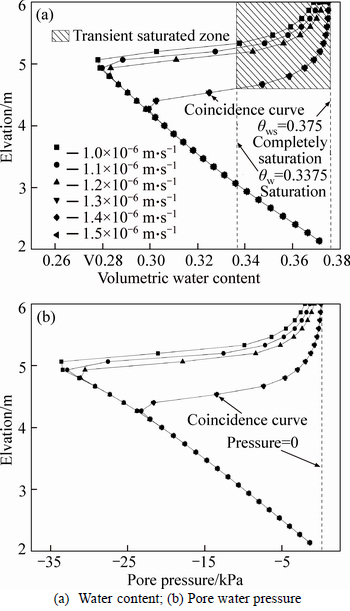
Fig. 11 Distribution of water content and pore water pressures in section I-I with different rainfall intensities:
Figure 12 shows the distribution in section I-I of the water content at different time for the rainfall intensity of 1.26��10-6 m��s-1 (q=ksat). After the rainfall starts, the surface becomes completely saturated in a short time (Sr=100%). When the rainfall ends (t=24 h), the depth of infiltration reaches up to 1.0 m and the transient saturated zone is about 0.85 m. Meanwhile, the completely saturated zone is about 0.25 m. After the stop of rainfall, the water in the transient saturated zone continuously infiltrates towards the downstream in the model. It is the dissipation of the transient saturated zone. 24 h after the stop of rainfall, the infiltration depth is about 1.85 m. 5 days after the stop of the rainfall, the infiltration depth increases to about 2.85 m. In the same time, the water content in the transient saturated zone decrease and so as its extension. At 48 h, the formed transient saturated zone disappears. However, the water content decreases always with the continuous water infiltration.
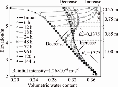
Fig. 12 Distribution of water content in section I-I at different time
Figure 13 shows the distribution of hydraulic gradient at different time in section I-I with the rainfall intensity as 1.26��10-6 m��s-1. During the rainfall (t=0-24 h), the maximum hydraulic gradient is located in the wetting front. The hydraulic gradient decreases with the infiltration depth. The reduction of hydraulic gradient is obvious owing to the decrease of water head differenceand the increase of seepage length.
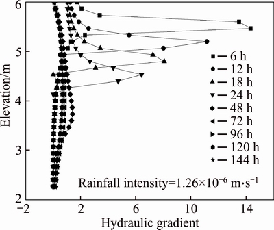
Fig. 13 Distribution of hydraulic gradient in section I-I at different time
4.2 2D seepage model
In this case, only one scheme has been considered (Table 2). It is mainly used to analyze the distribution of transient saturated zone with different rainfall intensities. Figure 14 shows the distribution of transient saturated zone at different time for the rainfall intensity as 1.26��10-6 m��s-1 (q=ksat). The model could be decomposed into four regions from the slope surface to the interior of the slope by the water contents: transient saturated zone, unsaturated zone, capillary suction saturated zone and original saturated zone. Transient saturated zone mainly due to the rainfall infiltration, and the extension of each zone changes with rainfall intensity, rainfall duration and some other factors. The unsaturated zone is the zone with the water content less than 0.3375. The formation of capillary suction saturated zone is due to the capillarity suction in the soil. The capillary suction leads to the upwelling of groundwater, and the corresponding saturated zone is formed when the water content reaches 0.3375. In this work, the capillary suction saturated zone is also exists in 1D model. The original saturated zone is the zone below the groundwater table. The zone has bedrock with quite low permeability. It is generally considered that this zone has negligible impact on the seepage in such model. As shown in Fig. 14, there is no transient saturated zone in the slope surface before the rainfall. After the rainfall starts, the rainwater infiltration velocity is greater than the penetration velocity of wetting front. It is leading to the transient saturated zone appears on the slope surface. And then with further rainwater infiltration, the transient saturated zone extends towards the interior of slope. In section II-II, the extension of transient saturated zone reaches 1.72 m when the rainfall stops.
Figure 15 shows the historical water contents at points a-g. It can be seen that before the stop of the rainfall, the water content of points a-g obviously increases. For points e, b, f and g, the distances to the ground surface (depth) are the same. The water contents of points e, b, and f decrease slowly, while the water content of point g decreases and then gradually increases. That mainly due to the infiltration parallel to the slope surface. The points a, b, c and d are located in Section II-II, the water contents of points a and b gradually drop while that at points c and d increases. This is mainly due to the water infiltration in the perpendicular diction of the slope. After the rainfall stops, the water continues to infiltrate in the slope in both directions. The water content at points e, b and f with higher elevation decreases earlier than those points with lower elevation. However, the latter has the supply of rainwater from its neighbors with higher elevation and higher water content. The water content in these points will later increase. For example, at the initial condition, the water content has the relationship: a
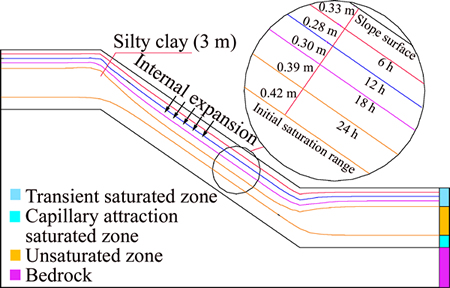
Fig. 14 Distribution of transient saturated zone inside slope (q=1.26��10-6 m��s-1)
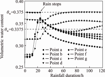
Fig. 15 Historical water contents at feature points inside slope
Figure 16 shows the distribution of water content in section II-II at different time. After a rainfall of 24 h, the transient saturated zone forms at the slope surface. The depth of saturated zone is about 1.5 m and the infiltration depth is about 1.87 m. The zone under the ground surface is divided into three zones (transient saturated zone, unsaturated zone and saturated zone). After the rainfall stops, the transient saturated zone begins to dissipate. While those locate deeper, the water content increases.

Fig. 16 Distribution of water content in section II-II at different time
The distribution of transient saturated zone at different times is demonstrated in Fig. 17. It can be seen that the transient saturated zone continues to develop in the slope surface and separates from capillary saturation zone at the stop of the rainfall. About 24 h after the stop of rainfall, the unsaturated zone appears at slope surface due to the rainwater infiltration in transient saturated zone. Meanwhile, the whole transient saturated zone moves downwards and merges with the capillary saturation zone. 48 h after the stop of the rainfall, the transient saturated zone at the top and bottom of the slope surface disappears due to the downwards infiltration, thus leading to the further expansion of the unsaturated zone at slope surface. 72 h after the stop of the rainfall, the groundwater table is raised up and the whole transient saturated zone disappears due to the convergence of transient saturated zone and capillary saturation zone. 96 h after the stop of rainfall, the groundwater table increases due to the rainwater infiltration. The augmented quantity of the groundwater table is inversely proportional to its original altitude inside the slope. Figure 18 shows the distribution and extension of transient saturated zone at different rainfall intensities. When the rainfall intensity is smaller than the saturated hydraulic conductivity, with the same rainfall duration, the larger rainfall intensity leads to the earlier formation of transient saturated zone and the larger extension. When, on the contrary, the rainfall intensity is greater than the saturated hydraulic conductivity, with the increase of rainfall intensity, there is no significant influence on the formation of transient saturated zone and its extension. Similar to that of 1D seepage model presented above, the rainfall intensity has a decisive dominant impact on the formation and development of transient saturated zone.
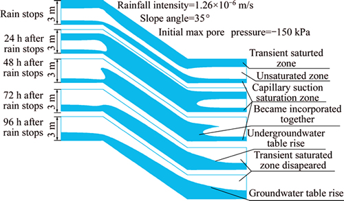
Fig. 17 Variation of transient saturated zone caused by rainfall
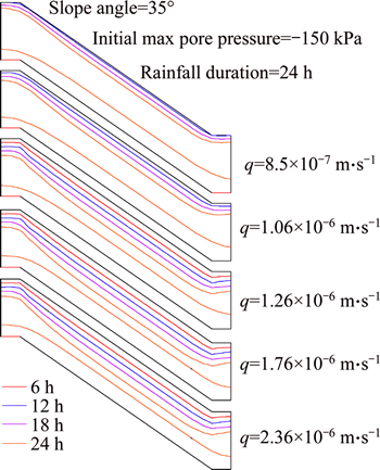
Fig. 18 The extension of transient saturated zone with different rainfall intensities
Figures 19 and 20 display the distribution of water content and hydraulic gradient under different rainfall intensities in section II-II when rainfall stops. The water content within the rainfall infiltration zone increases with the increase of rainfall intensity. The distribution of water content with the rainfall intensity of 2.36��10-7 m��s-1 is exactly the same as that of 1.76��10-6 m��s-1. As for the hydraulic gradient, it is the same for the two rainfall intensities: 2.36��10-7 m��s-1 and 1.76��10-6 m��s-1. The maximum value of hydraulic gradient for both former mentioned rainfall intensities is smaller than that 1.26��10-6 m��s-1. That is mainly due to the longer infiltration distance. When the rainfall intensity is 8.50��10-7 m��s-1 or 1.06��10-6 m��s-1, the smaller hydraulic gradients is observed. It can be concluded that the distribution and the maximum of hydraulic gradient in the slope are relevant to both the rainfall intensity and the depth of infiltration. This has also been verified in the 1D seepage model.
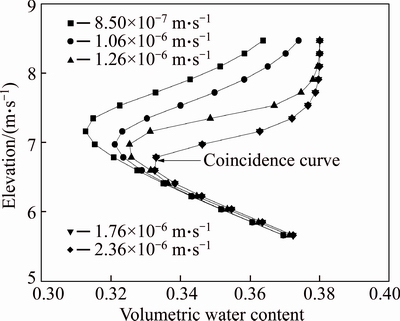
Fig. 19 Distribution of water contents in section II-II at rainfall stop (24 h)
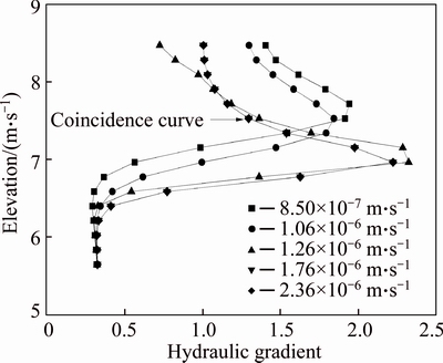
Fig. 20 Distribution of hydraulic gradient in section II-II at rainfall stop (24 h)
Based on the 1D and 2D seepage models, this section focuses on the formation, extension and dissipation of transient saturated zone under rainfall conditions. The results of 1D seepage model show that, the formation of transient saturated zone depends much on the rainfall intensity with given rainfall duration. When the rainfall duration is long enough, the small rainfall intensity may also trigger the transient saturated zone. The formation of transient saturated zone is ascribed to the downward infiltration velocity greater than that in the wetting front. After rainfall stop, the water in transient saturated zone continuously infiltrates downwards in the soil, leading to the decrease of saturation and the increase of the water content below the transient saturated zone. The numerical results of 1D seepage model also demonstrate the formation mechanism of transient saturated zone. Through the results of 2D slope seepage model, the development process of transient saturated zone has been demonstrated. The spatial distribution and its historical variation of transient saturated zone during and after the rainfall are revealed.
5 A case study
After the discussion of two academic seepage models, a real residual slope will be discussed in this section. The high cutting slope of expressway is located in Chenzhou City, Hunan Province, China. Its pavement locates at in the center of the slope with the height as 80 m. The slope ratios varies upwards from the pavement as 1:1, 1:1.5, 1:1.5, 1:1.5, as illustrated in Fig. 21. The slope surface covers gravel silty clay for about 7-20 m in depth, below which the weakly weathered limestone is located. Through the in-situ drilling survey, the natural groundwater table is about 2 m above the interface between the overburden and the bedrock. The recharge and dissipation are controlled by topography and soil structure, leading to the infiltration towards the foot of the slope. The mesh and initial groundwater table are shown in Fig. 21. There are totally 5100 quadrilateral elements and 5301 nodes.

Fig. 21 Geometric and calculation mesh of a slope
In order to obtain the hydraulic conductivity, the water pressure test in borehole was performed. The in-situ tests shown that the saturated hydraulic conductivity of weakly weathered limestone is about kwsx=kwsy=1.0��10-9 m��s-1. That of silty clay is obtained in the laboratory by the variable water heat test. It��s about kwsx=kwsy=8.3��10-6 m��s-1. The saturated water content of silty clay is about 0.35 and that of weakly weathered limestone is about 0.05. The residual water content of silty clay is about 0.02. The relative permeability of silty soil is determined by the formulation proposed by van GENUCHTEN [30] (Eq. (7)). The initial state is obtained by steady state calculation [32] and the initial matric suction of slope surface is set as -150 kPa.
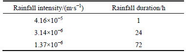
To study the slope seepage in the worst rainfall conditions, which given by the Bureau of Meteorology in Chenzhou, China, three rainfall cases are simulated with three largest rainfall intensities corresponding three different durations, namely 1 h, 24 d and 72 d as listed in Table 3.
Figure 22 shows the distributions of transient saturated zone and the locations of groundwater table during and after the rainfall with the rainfall intensity as 3.14��10-6 m��s-1 at different time. The results show that the transient saturated zone appears on the slope surface shortly after the start of rainfall. The extension of the transient saturated zone increases with rainfall duration and dissipates after the rainfall. The extension of transient saturated zone is larger at the slope foot, where the transient saturated zone is connected with the groundwater with rainwater infiltration. The saturated zone begins to dissipate downward along the slope after the stop of rainfall, while the groundwater table rises slightly due to the recharge of the underground water by the rainwater. From the above analysis, in the process of rainfall infiltration, the foot of the slope has the highest water level and the largest extension of transient saturated zone. Therefore, the treatment of slope foot should be more cost-effective and considered firstly for the slope protection. The possible measurements are such as increasing the drainage pipe length and its density at the foot area, keeping the drainage facilities unobstructed, etc. This can effectively prevent further extension of the transient saturated zone. Furthermore, the internal water level can be reduced and the effective stress in the soil at foot area will increase, and so as the shear strength which controls the stability of the slope.
Table 3 Rainfalls used in the case study
The historical areas of transient saturated zone for different scenarios are shown in Fig. 23. For the same slope, the formation of transient saturated zone is controlled by both the rainfall intensity and duration. With the largest rainfall intensity in Scheme 1, the transient saturated zone appears just in 12 minutes. And the extension velocity of such transient saturated zone is also the biggest. Comparing Scheme 2 and Scheme 3, the largest area of transient saturated zone in Scheme 2 is observed with a value of 467 m2.
6 Discussions and conclusions
Rainfall is one of the most important factors trigging the slope instability. The water infiltration leads to the reduction of soil shear strength. Simultaneously, the wet volumetric mass of soil increases and the matric suction decreases. As a result, rainfall causes the slope instability. The process can be generalized as: rainfall�� surface water�� water infiltration into the slope�� the increase of soil weight, the decrease of soil strength�� (the increase of probability of failure) �� shallow failure.
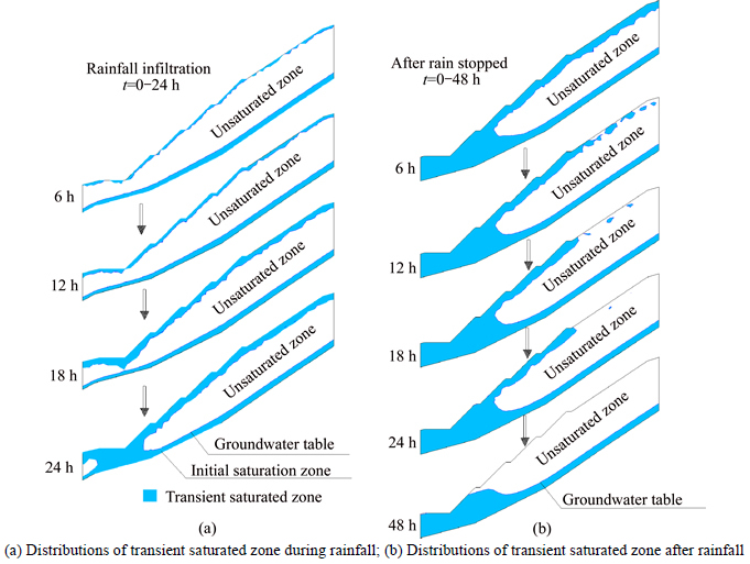
Fig. 22 Distributions of transient saturated zone and location of groundwater table at different times (Calculation scheme 2):
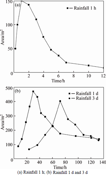
Fig. 23 Transient saturated area versus time:
This applies to all slope failures trigged by the rainfall infiltration. This work describes the variation of transient saturated zone within the slope, which is meaningful to analyzing the impact of soil weight and strength change on the slope stability. Moreover, there are different water storage regions at different rainfall time based on the fact that the transient saturated zone causes the raise of groundwater. Thus, it is worth trying the long and short drain pipe. Namely, the shorter drain pipe is used to drain the surface water in the early rainfall and the longer drain pipe to drain the internal water. Reducing the rainwater infiltration and employing the targeted approaches to drain the infiltration water are the objects to be done in the future work.
The present work focuses on the formation, distribution and dissipation of transient saturated zone within the slope. The variation of water content, matric suction, hydraulic gradient inside the slope due to the transient saturated zone are also analyzed. The results can be considered as the foundation for the investigation of rainfall induced residual soil slope instability. Some conclusions could be drawn as follows:
1) When the rainwater infiltration velocity is greater than the extrusion velocity at wetting front, the transient saturated zone appears in the slope. The formation time of transient saturated zone depends on the rainfall intensity, but its extension depends on both the rainfall intensity and duration.
2) The formation, development and dissipation of transient saturated zone are actually caused by rainfall infiltration. The relationship between rainfall intensity and the formation time of the transient saturated zone fits the power function, while the relationship between water content and rainfall intensity fits the logarithmic function, while that between infiltration depth and rainfall is linear function.
3) The sustained rainfall leads to the extension of transient saturated zone. After the rainfall stops, the zone dissipates towards the interior of slope, thus resulting in the unsaturated zone in the slope surface. Ultimately, the transient saturated zone converges with capillary saturation zone, leading to the raise of groundwater table.
4) In practical slope project, the extension of transient saturated zone is much larger at slope foot due to the infiltration parallel to the slope. As the rainfall continues, the transient saturated zone is connected with groundwater table at slope foot, leading to the increase of groundwater table.
5) Increasing the length and density of the drainage pipe at the foot area of slope and keeping the drainage facilities unobstructed can effectively prevent the development of transient saturated zone. The internal water level can be reduced and the effective stress of soil at the foot area will increase. The shear strength of soil will increase and the stability of the slope will be improved.
The work proposes the formation conditions and main contribution factors on the transient saturated zone with different models and rainfall scenarios. The whole duration of transient saturated zone: formation�C development�Cdissipation-groundwater recharge has been discussed in detail. Although there are many factors affecting the transient saturated zone, such as slope angle, step width, initial conditions, rainfall conditions, the ratio of kwsx and kwsx and the soil types, the paper focus only on the idea models. The influence of other factors or the multiple factors and the drainage measures will be discussed in the further work.
References
[1] TU X B, KWONG A K, DAI F C. Field monitoring of rainfall infiltration in a loess slope and analysis of failure mechanism of rainfall-induced landslides [J]. Engineering Geology, 2009, 105(1, 2): 134-150.
[2] RAHARDJO H, LIM T T, CHANG M F, FREDLUND D G. Shear-strength characteristics of a residual soil [J]. Can Geotech, 1995, 32(1): 60-77.
[3] FOURIE A B, ROWE D, BLIGHT G E. The effect of infiltration on the stability of the slopes of a dry ash dump [J]. Geotechnique, 1999, 49(1): 1-13.
[4] MUNTOHAR A S, LIAO H J. Rainfall infiltration: infinite slope model for landslides triggering by rainstorm [J]. Nat Hazards, 2010, 54(3): 967-984.
[5] FENG M, FREDLUND D G. Hysteretic influence associated with thermal conductivity sensor measurements [C]// Proceedings from Theory to the Practice of Unsaturated Soil Mechanics in Association with the 52nd Canadian Geotechnical Conference and Unsaturated Soil Group. 1999, 14: 214-14:220.
[6] HO D Y F, FREDLUND D G. A multi-stage triaxial test for unsaturated soil [J]. ASTM Geotechnical Testing Journal, 1982, 5(1, 2): 18-25.
[7] LI L Q, LUO S X, WANG Y C, WEI W K, LI C G. Model tests for mechanical response of bedding rock slope under different rainfall conditions [J]. Chinese Journal of Rock Mechanics and Engineering, 2014, 33(4): 755-762. (in Chinese)
[8] JIANG Z M, XIONG X H, ZENG L. Unsaturated seepage analysis of slope under rainfall condition based on FLAC3D [J]. Rock and Soil Mechanics, 2014, 35(3): 855-861. (in Chinese)
[9] ZENG Ling. Study of carbonaceous mudstone embankment stability under considering the unsaturated seepage and damage characteristics [D]. Changsha: Changsha University of Science and Technology, 2014. (in Chinese)
[10] TERZAGHI K. The shear resistance of saturated soils [C]// Proceedings of the XIth Danube-Europe Conference on Soil Mechanics and Geotechnical Engineering. Balkema: Geotechnical Hazards, 1998: 29-50.
[11] FREDLUND D G, MORGENSTERN N R, WIDGER A. Shear strength of unsaturated soils [J]. Canadian Geotechnical Journal, 1978, 3(15): 313-321.
[12] MILLER C J, YESILLER N, YALDO K, MERAYYAN S. Impact of soil type and compaction conditions on soil water Characteristic [J]. Journal of Geotechnical and Geo-Engineering, 2002, 128(9): 733-742.
[13] SUGII T, YAMADA K, KONDOU T. Relationship between soil- water characteristic curve and void ratio [C]// Proceedings of the 3rd International Conference on Unsaturated Soils. Rotterdam, Netherlands: Swets and Zeitlinger, 2002: 209-214.
[14] CUOMO S, DELLA M. Rainfall-induced infiltration runoff and failure in steep unsaturated shallow soil deposits [J]. Engineering Geology, 2013, 162: 118-127.
[15] DOU H Q, HAN T C GONG X N, ZHANG J. Probabilistic slope stability analysis considering the variability of hydraulic conductivity under rainfall in filtration�Credistribution conditions [J]. Engineering Geology, 2014, 183: 1-13. (in Chinese)
[16] OH S, NING L. Slope stability analysis under unsaturated conditions: Case studies of rainfall- induced failure of cut slopes [J]. Engineering Geology, 2015, 184: 96-103.
[17] BISHOP A W. The use of pore-pressure coefficients in practice [J]. Geotechnique, 1954, 4(4): 148-152.
[18] MORGENSTERN N R, PRICE V E. The analysis of the stability of general slip surface [J]. Geotechnique, 1965, 15(1): 79-93.
[19] DUNCAN J M. State of the art: Limit equilibrium and finite element analysis of slopes [J]. Geotechnique, 1996, 122(7): 577-596.
[20] BUSCARNERA G, WHITTLE A. Constitutive modeling approach for evaluating the triggering of flow slides [J]. Canadian Geotechnical Journal, 2012, 49(5): 499-511.
[21] BORJA R I, WHITE J A. Continuum deformation and stability analyses of a steep hillside slope under rainfall infiltration [J]. Acta Geotech, 2010, 1(5): 1-14.
[22] SUNG E C, SEUNG R L. Evaluation of surficial stability for homogeneous slopes considering rainfall characteristics [J]. Journal of Geotechnical and Geoenvironmental Engineering, 2002, 128(9): 756-763.
[23] RICHARDS L A. Capillary conduction of liquids through porous medium [J]. Physics, 1931, 1(5): 318-333.
[24] JOHN K. Stability modeling with slope/W2007 version [R]. Calgary, Canada: Geo-slope International Ltd, 2008: 315-331.
[25] TERZAGHI K, PECK R B. Soil mechanics in engineering practice [M]. New York: John Wiley, 1948.
[26] BISHOP A W, HENKEL D J. The measurement of soil properties in triaxial test [M]. Coefficient of Internal Friction, 1962.
[27] FREDLUND D G. Appropriate concepts and technology for unsaturated soils [J]. Canadian Geotechnical Journal, 1979, 16(1): 121-139.
[28] ALONSO E E, GENS A, JOSA A. A constitutive model for partially saturated soil [J]. Geotechnique, 1990, 40(3): 405-430.
[29] PAPAGIANNKIS A T, FREDLUND D G. A steady state model for flow in saturated�Cunsaturated soils [J]. Canadian Geotechnical Journal, 2011, 21(3): 419-430.
[30] van GENUCHTEN M T. A closed- form equation for predicting the hydraulic conductivity of unsaturated soils [J]. Soil Science Society of America Journal, 1980, 44(44): 892-898.
[31] SHAKOOR A. SMITHMYER A J. An analysis of storm-induced land-slides in colluvial soils overlying mud rock sequences, Southeastern Ohio, USA [J]. Engineering Geology, 2005, 78(3, 4): 257-274.
[32] ZENG L, FU H Y. ZHOU G K. Numerical simulation of effects of rainfall infiltration parameters on transient saturated areas of coarse-grained soil embankment [J]. Journal of Hohai University: Natural Science, 2014, 42(3): 250-256. (in Chinese)
(Edited by DENG L��-xiang)
Cite this article as:
ZENG Ling, BIAN Han-bing, SHI Zhen-ning, HE Zhong-ming. Forming condition of transient saturated zone and its distribution in residual slope under rainfall conditions [J]. Journal of Central South University, 2017, 24(8): 1866-1880.
DOI:https://dx.doi.org/https://doi.org/10.1007/s11771-017-3594-6Foundation item: Projects(51508040, 51578079, 51678074, 51678073) supported by the National Natural Science Foundation of China; Project(KFJ160601) supported by the Open Fund of Engineering Laboratory of Spatial Information Technology of Highway Geological Disaster Early Warning in Hunan Province (Changsha University of Science and Technology), China
Received date: 2016-10-09; Accepted date: 2017-02-23
Corresponding author: BIAN Han-bing, PhD, Associate Professor; Tel: +33-623976104; E-mail: hanbing.bian@univ-lorraine.fr
Abstract: Rainfall, as one of the most significant factors triggering the residual soil slope failure, leads to not only the reduction of soil shear strength, but also the increase of soil weight and the decrease of matric suction as well. All these modifications in soil properties have important influence on the slope stability. The water infiltration and redistribution inside the slope are the preconditions of the slope stability under rainfall conditions. Based on the numerical simulation via finite element method, the water infiltration process under rainfall conditions was studied in the present work. The emphases are the formation, distribution and dissipation of transient saturated zone. As for the calculation parameters, the SWCC and the saturated permeability have been determined by pressure plate test and variable head test respectively. The entire process (formation, development, dissipation) of the transient saturated zone was studied in detail. The variations of volumetric water content, matric suction and hydraulic gradient inside the slope, and the eventually raise of groundwater table were characterized and discussed, too. The results show that the major cause of the formation of transient saturated zone is ascribed to the fact that the exudation velocity of rainwater on the wetting front is less than the infiltration velocity of rainfall; as a result, the water content of the soil increases. On the other hand, the formation and extension of transient saturated zone have a close relationship with rainfall intensity and duration. The results can help the geotechnical engineers for the deeper understanding of the failure of residual slope under rainfall condition. It is also suggested that the proper drainage system in the slope may be the cost-effective slope failure mitigation method.
