
Trans. Nonferrous Met. Soc. China 20(2010) s1016-s1021

Industrial development of gas induced semi-solid process
S. THANABUMRUNGKUL1, S. JANUDOM1, R. BURAPA2, P. DULYAPRAPHANT3, J. WANNASIN1
1. Department of Mining and Materials Engineering, Faculty of Engineering, Prince of Songkla University,
Hat Yai, Songkhla, 90112, Thailand;
2. Department of Industrial Engineering, Faculty of Engineering, Rajamangala University of Technology Srivijaya, Songkhla, 90000, Thailand;
3. National Metal and Materials Technology Center, Thailand Science Park, Klong Luang,
Pathumthani 12120, Thailand
Received 13 May 2010; accepted 25 June 2010
Abstract:
The gas induced semi-solid (GISS) is a rheocasting process that produces semi-solid slurry by applying fine gas bubble injection through a graphite diffuser. The process is developed to be used in the die casting industry. To apply the GISS process with a die casting process, a GISS maker unit is designed and attached to a conventional die casting machine with little modifications. The commercial parts are developed and produced by the GISS die casting process. The GISS die casting shows the feasibility to produce industrial parts with aluminum 7075 and A356 with lower porosity than liquid die casting.
Key words:
gas induced semi-solid (GISS); rheocasting; die casting; semi-solid metal; industrial applications;
1 Introduction
Semi-solid die casting is one of the near-net shape manufacturing processes. Many advantages have been reported in the last 40 years compared with conventional die casting. For example, less gas porosity, reduced solidification shrinkage, heat treatment ability and reduced cycle times are some of the advantages[1-3]. There are two major routes to produce semi-solid slurry: thixocasting and rheocasting. High materials and production costs of thixocasting make it desirable only in niche applications[4]. The rheocasting route, thus, has been focused by many researchers over the last few years because of the lower machine investment and raw materials costs. Several rheocasting methods have been proposed to the casting industry, including the NRC[5], SSR[6], RDC[7], H-NCM[8], CRP[9], SEED[10] and SLC[11] processes. The majority of the rheocasting processes produce slurry at high solid fractions (~0.4-0.6). Although the properties of the parts produced using high solid fractions are better than low solid fractions (< 0.2), the high solid fraction slurry cannot be poured into the normal shot hole of a die casting machine. Many modifications of the processing machine are needed. Although semi-solid slurry at low fraction solid has some limitations in the applications because of oxides and contamination issue, it can provide low porosity of products, which is enough for many applications, especially in pressure tight market[12].
Recently, a simple and efficient process called the gas induced semi-solid (GISS) process has been invented[13]. The semi-solid slurry is produced by applying fine inert gas bubble injection through a graphite diffuser to agitate molten alloys during solidification. The process can be applied with die casting machines with minor modifications.
The added step occurs between the molten alloys transfer to the shot sleeve. The graphite diffuser is immersed to create a low solid fraction (~0.1) of semi-solid slurry, then the slurry is poured into the shot sleeve to produce a semi-solid casting part. Previous experiments have confirmed improvements of mechanical properties and reduction in gas porosity[14].
Although good results were obtained in these experiments, they were performed in laboratory scale. To apply in the die casting industry, it is important to develop this process to the industrial scale and test it with commercial parts. In this work, process description of the GISS die casting process with commercial parts was reported. The microstructure and porosity were investig-ated and the mechanical properties were also reported.
2 Gas induced semi-solid (GISS) process
Applying the knowledge that semi-solid structure can be efficiently formed by the combination of local rapid heat extraction and agitation[15], the GISS process used a graphite diffuser to introduce gas bubbles into the molten alloy just above the liquidus temperature. The molten alloy was cooled rapidly, and a number of fine globular grains were created just a few degrees below the liquidus. The inert gas injected to the molten alloy has two effects. One is to provide vigorous agitation and the other is to provide rapid heat extraction with the aid of the solid diffuser also. After the desired solid fraction is achieved, the diffuser is removed. Fig.1 shows the schematic diagram of the GISS process.
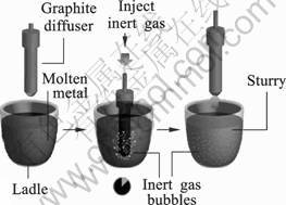
Fig. 1 Schematic diagram of gas induced semi-solid (GISS) process
3 Case studies of commercial part development by GISS die casting process
The GISS die casting process for industrial development was conducted with minor modifications from the conventional high-pressure die casting (HPDC) process. In the conventional HPDC process, the melt is transferred and poured to the shot sleeve directly. For the GISS die casting process, the GISS slurry maker was added during the melt transferred to the shot sleeve. In these experiments, the melt was taken from a graphite crucible in an electric furnace by a stainless steel ladle cup. Then, the melt was carried out by an operator to the GISS maker station. The porous graphite rod was immersed into the melt, and the inert gas flowed through the graphite rod into the melt until a desired temperature was obtained. The semi-solid slurry was created and then poured into the shot sleeve to produce a semi-solid casting part. Fig.2 shows the schematic diagram of the semi-automatic GISS die casting process.
3.1 Tube adapter for below knee prosthesis with aluminum 7075 alloy
Tube adapter parts were produced to prove the concept of porosity reduction by the semi-automatic GISS die casting process. Table 1 lists the chemical composition of the 7075 alloy used in this study. Table 2 lists the conditions of the experiments. The low solid fraction was created with different bubbling time of 5 and 10 s. The amount of solid fraction was analyzed by the rapid quenching mold method[16].
Table 1 Chemical composition of aluminum 7075 alloy (mass fraction, %)
![]()
Table 2 Bubbling time and solid fraction of aluminum 7075 alloy in experiments

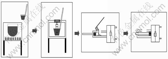
Fig.2 Schematic diagram of semi-automatic GISS die casting process
The sizes of the gate, runner and over flow of the GISS die casting part (7075-SF5 and 7075-SF10) were the same as the conventional liquid casting (7075-L). The gate thickness used in the experiment was 3 mm. The sample parts were prepared for porosity testing and cross section cut to observe the microstructure in two areas: on the top and near the gate. Fig.3 shows a tube adapter casting part.
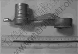
Fig.3 Aluminum 7075 tube adapter casting part
Fig.4 shows the cross section of an aluminum 7075 tube adapter part. Fig.5 shows the representative microstructures in the two areas of Fig.4, from the top (Area 1) and near the gate (Area 2). Figs.5 (a) and (b) show the liquid die casting microstructure with fine dendritic structure of �� phase in the top and near the gate of the part. Figs.5(c) - (f) show the microstructures of the GISS die casting part which have larger �� globular grains than the conventional liquid die casting part. In addition, the microstructures of GISS die casting part with the pouring solid fractions of 0.12 and 0.2 were quite similar.
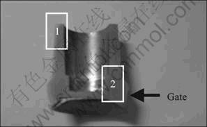
Fig.4 Cross section of aluminum 7075 tube adapter part
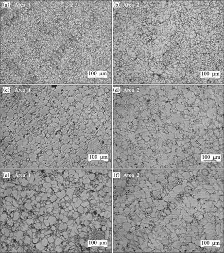
Fig.5 Representative microstructures of two areas in Fig.4 of tube adapter casting parts: (a), (b) Liquid casting; (c), (d) 7075-SF5; (e), (f) 7075-SF10
The average porosity of 7075 tube adapter liquid die-casting, semi-solid 7075-SF5 and 7075-SF10 are (5.27��1.3)%, (2.79��0.18)% and (2.88��0.25)%, respectively (Fig.6). The results show that the liquid die casting part has more porosity compared with the other GISS die casting parts. Although the GISS die casting parts still have porosity in the part, this may be solved with the new gate, runner and mold design, which will be conducted in a near future.
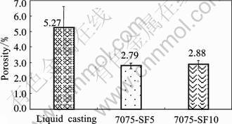
Fig.6 Porosity of 7075 tube adapter casting parts
3.2 Rotor cover parts with aluminum A356 alloy
A rotor cover was considered to be produced by the GISS die casting process with aluminum A356 alloy. Table 4 lists the chemical compositions of A356 alloy used in the study. The gate thicknesses of conventional A356 liquid die-casting and the GISS die casting are 1.5 and 4 mm, respectively. The GISS bubbling time was 5 s, which has yielded 0.10 fraction of solid. Table 5 lists a summary of the experimental conditions.
Table 4 Chemical composition of A356 aluminum alloy (mass fraction, %)
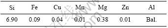
Table 5 Summary of experimental conditions
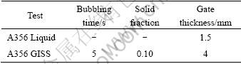
Fig.7 shows a rotor cover casting part, which was produced by the GISS process. The representative microstructure from the center of the part is shown in Fig.8. The dendritic structure is obtained in the liquid casting as presented in Fig.8(a). It can be seen from Fig.8(b) that the microstructure of A356 GISS die casting has more globular structure than the liquid casting.
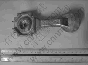
Fig.7 Aluminum A356 automotive casting part

Fig.8 Representative microstructures of die casting samples: (a)A356 liquid; (b)A356 GISS
The average porosity data of the A356 liquid die casting part and GISS die casting part are (2.09��0.26)% and (0.9��0.09)%, respectively. The results are shown in Fig.9.
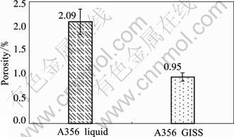
Fig.9 Porosity data of A356 automotive part liquid and GISS die-casting
The gas porosity or air bubbles were also observed by CT-SCAN testing. The three section areas of liquid and GISS die casting parts that were analyzed by the CT-SCAN are shown in Fig.10. Less porosity in the A356 GISS die casting parts is confirmed by the CT-SCAN testing, especially on the top and the bottom sections of the parts.
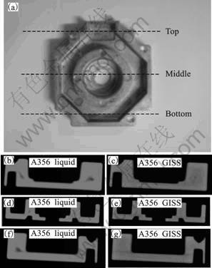
Fig.10 CT-SCAN results of liquid and GISS die casting of rotor cover in different areas: (b), (c) Top; (d), (e) Middle; (f), (g) Bottom
The T6 heat treatment was also conducted to compare the mechanical properties. The solution treatment was done at 540 ��C for 8 h. Then the artificial aging was carried out at 160 ��C for 8 h.
The tensile specimens were prepared by machining from the sides of the casting parts with the gauge length of 16 mm and 3 mm in thickness. The specimen and the drawing are given in Fig.11. The ultimate tensile strength (UTS) and elongation were analyzed. The results are presented in Fig.12.
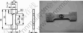
Fig.11 Tensile test specimen and drawing (Unit: mm)

Fig.12 Ultimate tensile strength and elongation of samples
The ultimate tensile strengths in the as-cast condition of the A356 liquid die-casting, A356 GISS die-casting are (162.1��16.6) and (235.3��13.1) MPa, respectively. The less porosity and gas bubbles of the GISS die casting result in higher tensile strength than the liquid die casting parts.
The elongation of the A356 liquid die-casting and A356 GISS die casting parts are (2.08��0.65)% and (10.21��2.8)%, respectively. This shows that less porosity of the GISS die casting process also increases the elongation significantly. The T6 heat treatment of the A356 GISS die casting parts increased the UTS and elongation of the sample to 293.3��7.70 MPa and (10.21��2.80)%, respectively. The results show the feasibility of heat treatment in A356 GISS die casting parts.
4 Future development of GISS die casting process
In the previous semi-automatic GISS die casting process, the melts and the semi-solid slurry were delivered manually by an operator. The process is not suitable for mass production. For continuous production, the GISS slurry maker must be integrated into the die-casting machine. To reach this concept, the ladle cup is attached to the die casting ladling arm. The molten alloy is ladled by the automatic ladling arm and transferred to the GISS slurry making station. In this station, the graphite rod will move down while inert gas is injected through the melt until the target solid fraction is achieved. The semi-solid slurry is then transferred and poured into the shot sleeve to produce a die-casting product. Fig.13 shows the schematic diagram of the automatic GISS die casting process, which is developed by GISSCO Co., Ltd.
5 Conclusions
1) The GISS die casting process is feasible to produce industrial parts with aluminum 7075 and A356. The process needs minor modifications to the conventional die casting machine and process.
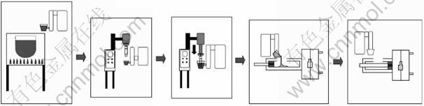
Fig.13 Schematic diagram of automatic GISS die casting process
2) The liquid die casting parts have more porosity than the GISS die casting part. The percentage of porosity and CT-SCAN testing confirmed the results.
3) The automatic GISS die casting system is developed by GISSCO Co., Ltd. in Thailand to apply with several industrial applications.
Acknowledgements
The authors would like to acknowledge the financial supports from Prince of Songkla University (No. AGR530031M) and the Royal Golden Jubilee Ph.D program (No.PHD/0173/2550). We also would like to thank our collaborators including National Metal and Materials Technology Center (MTEC), GISSCO CO., Ltd., Mattel Bangkok CO., Ltd. and UMC die casting CO., Ltd.
References
[1] FLEMINGS M C. Behavior of metal alloys in the semi-solid [J]. Metallurgical Transactions A, 1991, 22: 957-981.
[2] KIRKWOOD D H. Semi-solid metal processing [J]. International Materials Reviews, 1994, 39:173-189.
[3] FAN Z. Semisolid metal processing [J]. International Materials Reviews, 2002, 47: 49-85.
[4] JORSTAD J, THIEMAN M, KAMM R. SLC the newest and most economical approach to semi-solid metal (SSM) casting [C]//The 7th International Conference on Semi-Solid Processing of Alloys and Composite. Tsukuba, Japan, 2002: 701-706.
[5] UBE Industries Ltd. Method and apparatus for shaping semi-solid metal. EPO 745 694 A1 [P], 1996.
[6] YURKO J A, MARTINEZ R A, FLEMINGS M C. Development of the semi-solid rheocasting (SSR) process [C]//The 7th International Conference on Semi-Solid Processing of Alloys and Composites. Tsukuba, Japan, 2002: 659-664.
[7] FAN Z. Development of the rheo-diecasting process for magnesium alloys [J]. Materials Science and Engineering A, 2005, 413/414: 72-78.
[8] HONG C P, KIM J M. Development of an Advanced Rheocasting Process and its Application [C]//The 9th International Conference on Semi-Solid Processing of Alloys and Composites. Busan, Korea, 2006: 44-53.
[9] PAN Q Y, WIESNER S, APELIAN D. Application of the continuous rheoconversion process (CRP) to low temperature HPDC-Part I: Microstructure [C]//The 9th International Conference on Semi-Solid Processing of Alloys and Composites. Busan, Korea, 2006: 402-405.
[10] DOUTRE D, LANGLAIS J, ROY S. The SEED process for semi-solid forming [C]//The 8th International Conference on Semi-Solid Processing of Alloys and Composite. Limassol, Cyprus, 2004.
[11] JORSTAD J, THIEMAN M, KAMM R. Fundamental requirements for slurry generation in the sub liquidus casting process and the economics of SLCTM processing [C]//The 8th International Conference on Semi-Solid Processing of Alloys and Composites. Limassol, Cyprus, 2004.
[12] KIRKWOOD D H, SUERY M , KAPRANOS P, ATKINSON H V, YOUNG K P. Semi-solid processing of alloys [M]. London: Springer Series in Materials Science, 2009: 48-56.
[13] WANNASIN J, MARTINEZ R A, FLEMINGS M C. A novel technique to produce metal slurries for semi-solid metal processing [J]. Solid State Phenomena, 2006, 116: 366-369.
[14] WANNASIN J, JUNUDOM S, RATTANOCHAIKUL T, FLEMINGS M C. Development of the gas induced semi-solid metal process for aluminum die casting application[J]. Solid State Phenomena, 2008, 141-143: 97-102.
[15] MARTINEZ R A, FLEMINGS M C. Evolution of particle morphology in semisolid processing[J]. Metallurgical and Materials Transactions A, 2005, 36: 2205-2210.
[16] WANNASIN J, CANYOOK R, BURAPA R, FLEMINGS M C. Evaluation of solid fraction in a rheocast aluminum die casting alloy by a rapid quenching method[J]. Scripta Materialia, 2008, 59: 1091-1094.
(Edited by LI Xiang-qun)
Corresponding author: J. WANNASIN; Tel: +66-74-287-312; E-mail: jessada.w@psuac.th, jessada@alum.mit.edu
