
J. Cent. South Univ. (2016) 23: 1301-1311
DOI: 10.1007/s11771-016-3180-3

Influence of welding speed on corrosion behaviour of friction stir welded AA5086 aluminium alloy
Kamran Amini, Farhad Gharavi
Department of Mechanical Engineering, Tiran Branch, Islamic Azad University, Isfahan, Iran
 Central South University Press and Springer-Verlag Berlin Heidelberg 2016
Abstract:
The plates of AA5086 aluminium alloy were joined together by friction stir welding at a fixed rotation speed of 1000 r/min various welding speeds ranging from 63 to 100 mm/min. Corrosion behavior of the parent alloy (PA), the heat affected zone (HAZ), and the weld nugget zone (WNZ) of the joints were studied in 3.5% (mass fraction) aerated aqueous NaCl solution by potentiodynamic polarization and electrochemical impedance spectroscopy (EIS). The corrosion susceptibility of the weldments increases when the welding speed increases to 63 and 100 mm/min. However, the value of corrosion rate in the weldments is lower than that in the PA. Additionally, the corrosion current density increases with increasing the welding speed in the HAZ and the WNZ. On the contrary, the corrosion potential in the WNZ appears more positive than in the HAZ with decreasing the welding speed. The WNZ exhibits higher resistance compared to the HAZ and the PA as the welding speed decreases. The results obtained from the EIS measurements suggest that the weld regions have higher corrosion resistance than the parent alloy. With increasing the welding speed, the distribution and extent of the corroded areas in the WNZ region are lower than those of the HAZ region. In the HAZ region, in addition to the pits in the corroded area, some cracks can be seen around the corroded areas, which confirms that intergranular corrosion is formed in this area. The alkaline localized corrosion and the pitting corrosion are the main corrosion mechanisms in the corroded areas within the weld regions. Crystallographic pits are observed within the weld regions.
Key words:
friction stir welding; aluminum alloy; corrosion properties; welding speed��
1 Introduction
Friction stir welding (FSW) is an advanced solid- state welding process invented and developed by TWI (UK) in 1991 [1]. In this process, a rotating, non- consumable tool was driven and moved into the material along the joint line of two parent plates. The material was heated up by friction generated between the shoulder of the tool and the surface of the parent plate to be welded. The plasticized material is extruded from the leading edge to the trailing edge of tool and is forged by the larger pressure produced from the tool shoulder and pin to fabricate the joint [2-6]. This welding technique creates special micro-structures and properties that have heterogeneous features from those appearing in traditional fusion welding. According to different welding parameters, weld regions can contain several sub- domains with various microstructures, including different structural zone, such as weld nugget zone (WNZ), heat affected zone (HAZ), thermo-mechanical affected zone (TMAZ) and parent alloy (PA). The distinctly different micro-structure produced by the FSW process can change the mechanical properties and corrosion feature of the weld regions, as is the case with most welding processes [7]. Meanwhile, Effect of microstructure on corrosion rate is significant. Previous studies have documented that the welded regions of the most welded joints are susceptible to corrosion [8-15]. They showed that both heterogeneous and multiphase microstructure can reduce corrosion resistance. In this regard, BOUSQUET et al [16] reported that the HAZ close to the TMAZ is the most sensitive to intergranular corrosion because of the presence of continuous lines of S��(S) intergranular precipitates at grain boundaries. Additionally, the WNZ in AA6061 [8], AA7075 [17], AA2050 [13-14], AA2024 [18-19], AA7055 [20] and AA5052 [9] also show susceptibility to localized corrosion attacks in comparison to the PA. For FSWed AA6005-T6, DONG et al [10] showed that the coarsening of the intergranular Q and Si precipitates as well as the precipitation of the intergranular Q�� phases in the HAZ reduced the micro galvanic driving force causing IGC and introduced the pitting corrosion. Moreover, previous researches have reported that friction stir welds of the AA5xxx alloy presented various corrosion resistance from the parent alloy [21-26]. The 5086 aluminum alloy is a non-heat treatable alloy with medium to high strength which has better formability than the other aluminum alloys such as 5083 alloy. AA5086 aluminum alloy can resist stress corrosion cracking and exfoliation; it has become widely used in the marine, automotive, and aerospace industries [27-28]. The welded joints from this type of aluminium alloy by FSW exhibit different mechanical properties with compared to the parent alloy. In this respect, although some studies have been conducted to investigate the effect of FSW process on the microstructure and mechanical properties of this alloy [26-31], its corrosion behavior has received scarce consideration. To address this issue, the current work combines microstructural characterization and corrosion testing of the AA5086 friction stir welds not only to identify the corrosion behaviour as a function of position in the weld, but also to correlate that information to the underlying microstructure of those regions and identify the microstructural basis for those behaviours. This approach provides a comprehensive understanding of the causes of the observed corrosion behaviour as a function of position within the AA5086 friction stir welds.
2 Experimental details
2.1 Material
A non-heat treatable 5086 aluminum alloy plate with a thickness of 8 mm was used in the present work as the parent alloy. Nominal composition of the parent alloy is given in Table 1.
2.2 Welding procedure
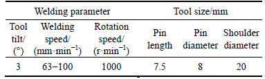
The friction-stir welding (FSW) process and the joint design utilized in this research are schematically presented in Fig. 1. As can be seen in this figure, the dimensions of each plate were up to 300 mm in length and 100 mm in width, so that they could be longitudinally butt welded parallel to the rolling direction of the plate using a CNC milling machine. The non-consumable designed welding tool conditions employed for welding in this work and the welding conditions are listed in Table 2.
2.3 Corrosion experiments
To compare the corrosion behavior of the test samples, electrochemical experiments including Tafel polarization and electrochemical impedance spectroscopy (EIS) tests were performed by a PARSTAT2273 machine equipped with power suit software according to the ASTM standards [32-33] in 3.5% (mass fraction) NaCl aerated aqueous solution (pH=5.5) at ambient temperature. Before placing test samples in the open glass vessel used as a corrosion cell containing the test solution, the samples were embedded in cold-setting resins, so that only a single surface would be exposed to the test solution, and they were electrically connected with a copper wire after being set in a polyethylene tube. Right before each experiment, the surface of the sample was dipped in concentrated HNO3 for 30 s. Electro- chemical measurements consisted of a standard three electrode with the sample as a working electrode including the PA, WNZ, and HAZ regions (1 cm2), a saturated calomel electrode SCE (0.242 V vs SHE) as a reference electrode, and a graphite rod as the counter electrode. Measurements for the Tafel polarization curves were recorded in the potential range from -0.25 mV to +0.75 mV with respect to the OCP and at the scan rate of 1 mV/s after allowing a steady-state potential to develop for 30 min. Corrosion potentials (��corr) and corrosion current densities (Jcorr) were calculated by the Tafel extrapolation methods. In addition, electrochemical impedance spectroscopy (EIS) experiments were carried out at OCP over a frequency ranging from 100 kHz to 10 mHz, with the voltage amplitude of 10 mV being superimposed on the test. Fitting of experimental impedance spectroscopy data to the proposed equivalent circuit was done by Zsimwin 3.21 software. All the experiments were repeated at least twice to ensure reproducibility.
2.4 Structural characterization
After the welding process, the test samples consisted of the parent alloy (PA), the weld nugget zone (WNZ), and the heat affected zone (HAZ). The samples were used in the flat type after they were carefully prepared by applying standard metallographic techniques, including wet-grinding operation with water using emery paper of SiC with different grit number sequences of 400, 600, 800 and 1200, followed by polishing with 1 ��m non-aqueous diamond paste, degreasing by acetone, washing with double distilled water, and drying. The samples were etched by immersion into a suitable etchant solution composed of 15 mL (HNO3), 10 mL (HF), and 100 mL (H2O). Microstructural examination of the butt welded joints before and after corrosion test was carried out by scanning electron microscopy (SEM), and energy dispersive spectroscopy (EDS).
Table 1 Chemical compositions (mass fraction) and mechanical properties of 5086 aluminum alloy.

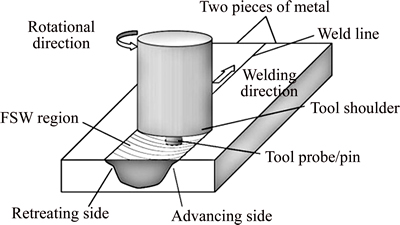
Fig. 1 Schematic diagram of friction stir welding process and joint design used in this work
Table 2 Tool size and welding parameters used in experiments
3 Results and discussion
3.1 Micro-structural analysis of weldments before corrosion
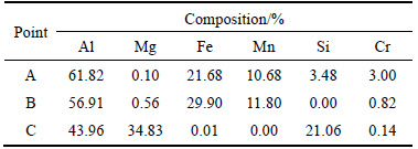
Generally, the intermetallic precipitates in the Al-Mg alloy are classified into constituents and dispersoids. The constituent precipitates contain two types of phases, i.e. insoluble and soluble [34]. In this regard, the SEM equipped with EDS analysis performed at the transverse section reveals two kinds of intermetallic precipitates within the parent alloy. The intermetallic precipitates contain the Fe-rich particles and the Mg-Si rich particles (Fig. 2). The EDS analysis is illustrated in Table 3. The iron-rich particles are detected in two forms, Al6(Fe-Mn) and Al(Fe-Mn-Si-Cr), which are classified as insoluble due to their high melting points, as illustrated in Fig. 2. Coarse iron-rich particles are observed as the irregular shape, different size, and a random distribution within the alloy matrix. Additionally, the magnesium- and silicon-rich particles are identified as the other phase in the alloy matrix. This phase is indicated as the gray spots in an almost good contrast with the adjacent alloy matrix in back scattered imaging method, as shown in Fig. 2. The iron- and magnesium- rich particles are found in different sizes, estimated to be in the range of about 3-75 ��m within the parent alloy.
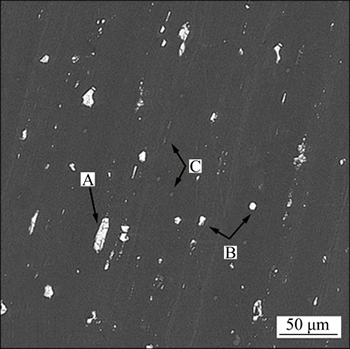
Fig. 2 BSE micrograph image of intermetallics identified in parent alloy (A-Al(Fe-Mn-Si-Cr); B-Al(Fe-Mn); C-Al(Mg-Si))
Table 3 EDS analysis result (mass fraction, %) of different intermetallic particles highlighted in parent alloy shown in Fig. 2
It is noteworthy that as reported in Refs. [35-38], the corrosion attacks mainly take place at the vicinity of the area surrounding the Fe-rich particles. This process appears even after lowering the immersion time in the AA5xxx aluminum alloys with acceptable corrosion resistance. Corrosion attack leads to creating grooves and pits in the alloy matrix. Statistical analysis of the grooves and pits formed near the iron-rich particles shows that the presence of the Cr and Si elements does not influence the susceptibility of these particles to corrosion attacks. Therefore, it seems that the corrosion mechanism of both Al6(Fe-Mn) and Al(Fe-Mn-Si-Cr) particles is similar. On the other hand, it is reported that the particles of Al(Mg-Si) contain the same or lower corrosion potential than the Al matrix. Thus, the corrosion mechanism of these particles is inactive [38].
It is worth mentioning that the FSW process shows a great effect on the intermetallic precipitates size and distribution in the weld region owing to the influence of the FSW process. The effect of welding speeds on the size and distribution of intermetallic precipitates in the weld regions is presented in Figs. 3-4. Accordingly, in the HAZ, it is obvious that both the iron- and magnesium-rich particles are fragmented into smaller sizes as the welding speed increases. This may be attributed to the insufficiency of the temperature during joining to dissolve by the contact between the particles and the rotating tool (Fig. 3). Coarse iron-rich particles are crushed by the rotating tool during its moving into uniformly distributed fine and small particles. Moreover, their population density increases within the weld nugget region with the increase of the welding speed (Fig. 4). It is clear that within the parent alloy and the HAZ, some areas appear to include high population density of intermetallic particles; in other areas, low population density is identified.
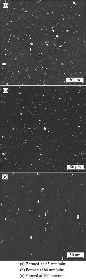
Fig. 3 BSE micrograph images of intermetallic identified in HAZ at different welding speeds:
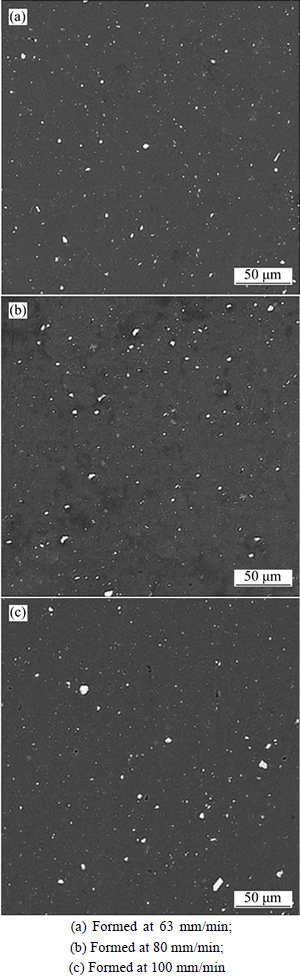
Fig. 4 BSE micrograph images of intermetallic identified in WNZ at different welding speeds:
3.2 Electrochemical results
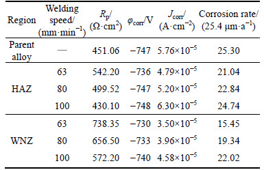
Figure 5 shows the Tafel polarization curves of the parent alloy (PA) and the weld regions (i.e. the WNZ and HAZ) in the as-welded condition at different welding speeds. The electrochemical parameters such as the corrosion potential (��corr) and the corrosion current density (Jcorr) were determined by extrapolation of the cathodic Tafel lines to the corrosion potential. The electrochemical results obtained for the parent alloy and the weld regions are reported in Table 4. As shown in Fig. 5, all the Tafel plots present the same overall shape with only one break-down of the potential related to the corrosion potential. The corrosion potential is followedby a sharp increase of the corrosion current density. This means that no passivation plateau is observed, which indicates that the parent alloy and the weld regions are susceptible to corrosion at their corrosion potential. It should be noted that all the Tafel curves exhibit a cathodic plateau corresponding to the oxygen reduction reaction. According to Table 4, the value of the corrosion current density moves to cathodic direction with decreasing the welding speed, leading to improvement of the corrosion resistance compared with the parent alloy. The corrosion susceptibility of the weldments increases when the welding speed increases to 63 and 100 mm/min. This can be explained by the fact that with increasing the welding speed, due to increasing of precipitates deterioration in the weld regions, the amount and distribution of the precipitates increase in the alloy matrix. The high dispersion of the precipitates in the alloy matrix allows the susceptibility to corrosion of these zones to be explained. Galvanic coupling between precipitates which have a corrosion potential that is more negative than that of matrix, and the surrounding matrix promote the propagation of corrosion in the two regions as the welding speed increases. From the standpoint of pitting, it can be said that the smaller precipitates affect the formation of deeper pits than the larger precipitates due to the lowering of local increase in pH. Moreover, the resistance polarization decreases as opposed to the corrosion current density with increasing the welding speed. Compared to the parent alloy, in all welding conditions, the polarization resistance increases and the corrosion current density decreases in the nugget zone. This means that the parent alloy shows higher susceptibility to corrosion and particularly pitting as opposed to the nugget zone. Therefore, the corrosion rate of the weldments increases with increasing the welding speed. However, the value of corrosion rate in the weldments is lower than that in the parent alloy.
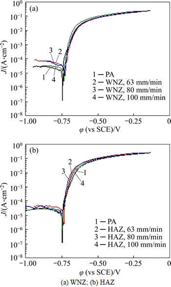
Fig. 5 Tafel polarization curves for different weld regions at various welding speeds:
Table 4 Corrosion parameters determined by Tafel extrapolation test for different weld regions at various welding speeds
The impedance diagrams for the parent alloy and the different weld regions including the WNZ and HAZ are shown in Fig. 6 in the form of both Nyquist and Bode plots. The experimental data are fitted using appropriate equivalent circuits within the limits of experimental error (<3%). The equivalent circuits used to fit the experimental plots are shown in Fig. 7. Rsol corresponds to the electrolyte resistance, Rpolar and Cdl represent the polarization resistance and double layer capacitance, Rop is the film resistance corresponding to the outer porous layer and the inner compact layer resistance is denoted as Ric. Constant phase elements (CPE, Q) instead of capacitors are used in the equivalent circuit model to account for dispersive characteristic of the time constants and heterogeneous properties of the layers. Moreover, in the simulation of the impedance plots, the constant phase element (CPE) is applied instead of the ��ideal�� capacitance.
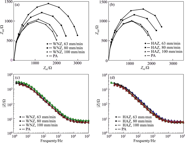
Fig. 6 Nyquist (a,c) and Bode (b,d) plots for different weld regions at various welding speeds
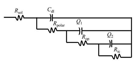

Fig. 7 Equivalent circuit models used for EIS data fitting
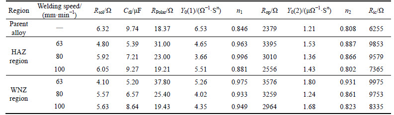
The various corrosion parameters obtained by fitting the equivalent circuit are listed in Table 5. From these results, it can be found that the oxide layers of the aluminium alloy are composed of two parts. Upon exposure of aluminium to air, the aluminium oxide is formed on its surface, and after exposure to aqueous solution, another layer is also formed on its surface, which is generally caused by the hydration of aluminium [39]. The frequency power values indicate that the inner layer is denser due to the constants of the two layers. In addition, it can be found that these layers have good adhesion together. Indeed, it can be seen from Table 5 that the variations in the Rop and Ric values clearly display the poor corrosion behavior of the outer layer as the resistance value is much lower compared with the inner compact layer (Ric). The rate of the corrosion processes can be estimated measuring the polarization resistance (Rpolar). Comparing the values of the polarization resistance of the parent alloy and the weld regions reveals that although the corrosion resistance increases with increasing the welding speed, this rate is significantly in lower speeds.
Furthermore, the resistance of the oxide layers increases with decreasing the welding speed. This is attributed to the lowering of local increase in pH surrounding the precipitates [35-37]. As can be seen from the Nyquist plot in Figs. 6(a) and 7(a), when the welding speed decreases from 100 to 63 mm/min, the WNZ and HAZ have higher impedance compared to the parent alloy because the semicircle radios of the Nyquist plot increase. The low frequency impedance indicates the corrosion resistance. Hence, higher impedance value at low frequency indicates better corrosion resistance. Thus, the weld nugget region exhibits higher resistance compared to the HAZ and the parent alloy as the welding speed decreases. In other words, the semicircle radios of the Nyquist plot follows WNZ>HAZ>PA in the same solution. This means that the resistance of the oxide layers near the cathodic precipitates significantly increases in the weld nugget zone. Therefore, the amount of corrosion intensity surrounding the cathodic precipitates can increase in the WNZ as opposed to the HAZ and the parent alloy. Increasing the value of the capacitance (C) shows that the double layer capacitance increases. This means that the value of diffusion increases through this layer and as a result, the corrosion rate will increase. Moreover, although the bode plots have not clearly permitted to conclude the better electrochemical behavior for these examined samples, the aforementioned Nyquist plots induced the WNZ samples better than both the PA and HAZ, as previously demonstrated. The results obtained from the EIS measurements suggest that the weld regions have higher corrosion resistance than the parent alloy.
Table 5 Simulated parameters of EIS data of parent alloy and weld regions obtained in 3.5% NaCl solutions (pH 5.5) at various welding speeds
3.3 Corrosion morphology of parent alloy
Figure 8 shows the corrosion morphology observed after electrochemical tests for the parent alloy in the 3.5% NaCl solution. As can be seen in Fig. 8, the corroded areas are created locally on the surface, but the whole of the surface is uncovered. The localized corrosion attack contains numerous grooves throughout the surface of sample. The localized corrosion occurs entirely around the precipitates in the parent alloy matrix. These precipitates are mainly formed in types of Al6(Fe-Mn) and Al(Fe-Mn-Si-Cr). Due to the presence of these precipitates in various dimensions in the parent alloy matrix, the extent of the corroded areas is different, so that around the larger precipitates a wider corroded area is formed on the surface. It is important to note that in those areas of the surface where other types of precipitates such as Al(Mg-Si) are present, no localized corrosion attack is observed. This is attributed to the same or less corrosion potential of these types of precipitates than the Al matrix. According to Fig. 9, it can be concluded that formed pits are crystallographic.In other words, the localized corrosion is in the form of crystalline pitting corrosion [36]. It should be noted that there is no relationship between the formation of crystalline pit and the presence of intermetallic precipitates. This formation is directly related to the amount of the current density applied to the sample. In this regard, it is proven that the crystalline pits are formed in the higher current density of 0.5 ��A/cm2. The reason of this phenomenon corresponds to the deterioration of the oxide film on the surface of specimen. When the oxide film is removed, the open circuit potential (OCP) moves toward the nucleation pitting potential on the matrix phase and the result of this action is the formation of crystallographic pits [36].
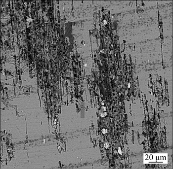
Fig. 8 BSE micrograph of corrosion morphology of parent alloy (PA)
3.4 Corrosion morphology of heat affected zone (HAZ)
Figure 10 presents the SEM images of the corrosion morphology of the HAZ at different welding speeds. As can be seen, not all the surface samples have been corroded, but some areas of surface samples have been corroded locally. This is attributed to the presence of intermetallic precipitates in these areas. With more carful observation, it is found that the corroded areas are expanded with decreasing the welding speed, but the depth and severity of the pitting corrosion are less. Lower corrosion current densities obtained from the polarization curves in this region by reducing the welding speed also confirm this matter. Despite the slope of temperature gradient in this region, due to the decreasing of the welding speed, the large intermetallic precipitates of the parent alloy have been smaller and more widely distributed in this region. This is attributed to the dissolution and re-precipitation of intermetallic particles. Due to the fining of precipitates and their distribution in this region, although the numbers of suitable sites for corrosion and oxygen reduction are increased, the local pH is decreased. Here, the oxide film is less destroyed around the precipitates and the corrosion process occurs with less intensity at the interface of the matrix and precipitates. In this regard, the size and number of pits are less than those of the parent alloy. Therefore, it can be concluded that the corrosion resistance of the HAZ has increased with decreasing the welding speed. The polarization and impedance curves also confirm this matter. On the other hand, other precipitates such as Al(Mg-Si) are presented in the HAZ as well as in the parent alloy. However, no specific change (i.e. corrosion) occurs in the HAZ. As the melting point of these precipitates is higher than 450 ��C [39] and the temperature is not above 450 ��C in this region, these precipitates have not been resolved in the matrix. Indeed, the pits formed in this region are crystallographic pits which are the same as the parent alloy, but the extent and severity of the pits decline by reducing the welding speed, due to the lower corrosion current density in this region than the parent alloy (Fig. 11).
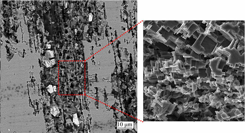
Fig. 9 BSE micrographs of crystallographic pits
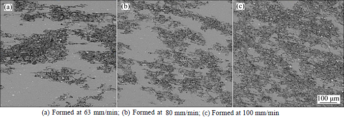
Fig. 10 BSE micrographs of corrosion morphology of HAZ at different welding speeds:
3.5 Corrosion morphology of weld nugget zone (WNZ)
Micro-structural analysis of the surface of the weld nugget zones after corrosion test at different welding speeds is shown in Fig. 12. It is clear that a variety of areas on the surface have been corroded locally. With increasing the welding speed, the distribution and extent of the corroded areas in this region are lower than those the HAZ region. Due to severe deformation that occurs in this region, the precipitates are quite fine and small; moreover, they are more widely distributed in this region. Whereas, by reducing the size of precipitates with decreasing welding speed, suitable sites for micro-galvanic corrosion have increased, but the corrosion rate in these areas declines. The corrosion current density calculated from the polarization curve for this region also confirms this matter. Because of the stirring and higher temperature in this region compared to the HAZ, the Al6(Fe-Mn) and Al(Fe-Mn-Cr) precipitates are smaller and their distribution is more. However, because it has a melting point of about 650 ��C [40], these precipitates have not been dissolved in this region. But the Al(Mg-Si) precipitates have been fully dissolved in this zone (Fig. 12). So, corrosion has occurred only by the Al6(Fe-Mn) and Al(Fe-Mn-Si-Cr) precipitates in the WNZ. Due to the fact that an increase in the pH surrounding the precipitates in this region is less than that in the HAZ; the corrosion resistance is higher in the weld nugget zone. With a more careful consideration of Fig. 12, it is concluded that in addition to the pits in the corroded area, some cracks can be seen around the corroded areas, which confirms that intergranular corrosion is formed in this area. Pitting corrosion phenomena together with intergranular attacks have also been reported by ZHANG et al [41]. Intergranular corrosion near the corroded area, as defined and developed areas in the vicinity of the pitting sites, can be observed. When pitting is formed as a relatively continuous network along the grain boundaries, intergranular corrosion is developed and expanded. The close distance of polarization and impedance curves in this region compared to the HAZ can be caused by intergranular corrosion along with pitting corrosion in the WNZ. The crystallographic pits can also be seen in this region, but their intensity is far less than that in the area of the HAZ and the parent alloy (Fig. 13).
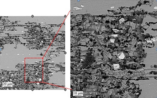
Fig. 11 BSE micrograph of crystallographic pits formed in HAZ at welding speed of 63 mm/min
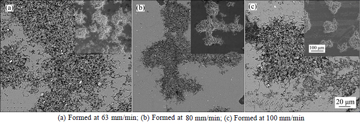
Fig. 12 SEM micrographs of corrosion morphology of WNZ at different welding speeds:
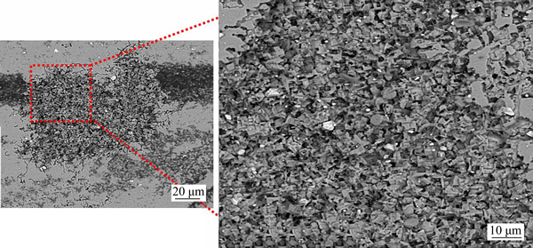
Fig. 13 BSE micrographs of crystallographic pits formed in HAZ at welding speed of 63 mm/min
4 Conclusions
1) The AA5086 alloy contains coarse white particles indexed as Al6(Fe-Mn) and Al(Fe-Mn-Si-Cr) and fine gray particles as the Mg and Si phases.
2) With increasing the welding speed, the corrosion current density in the HAZ and the WNZ increases; however, the corrosion potential in the HAZ is more negative than in the WNZ.
3) Localized alkaline corrosion with crystallo- graphic pitting corrosion is determined as two types of localized corrosion at the corroded areas in each of the weld regions.
References
[1] THOMAS W M, NICHOLAS E D, NEEDHAM J C, MURCH M G, TEMPLE-SMITH P, DAWES C J. Friction stir welding and processing [P]. International patent application No. PCT/GB92/ 02203 and GB Patent Application No. 9125978.8 and US Patent Application No. 5460317. 1991-09.
[2] TEJONADHA B K, KRANTHI K P, MUTHUKUMARAN S. Mechanical, metallurgical characteristics and corrosion properties of friction stir welded AA6061-T6 using commercial pure aluminium as a filler plate [J]. Procedia Materials Science, 2014, 6: 648-655.
[3] DAWES C J, THOMAS W M. Friction stir process weldsaluminium alloys: The process produces low-distortion, high-quality, low-cost welds on aluminium [J]. Welding Journal, 1996, 75: 41-45.
[4] D��URSO G, GIARDINI C. The influences of process parameters and tool geometry on mechanical properties of friction stir welded aluminum lap joints [J]. International Journal of Material Forming, 2010, 3: 1011-1014.
[5] CANTIN G M D, DAVID S A, THOMAS W M, LARA-CURZIO E, BABU S S. Friction skew-stir welding of lap joints in 5083-O aluminium [J]. Science and Technology of Welding and Joining, 2005, 10: 268-281.
[6] KULEKCI M K,  E. Effects of tool rotation and pin diameter on fatigue properties of friction stir welded lap joints [J]. International Journal of Advanced Manufacturing Technology, 2008, 36: 877-882.
[7] MISHRA R S, MA Z Y. Friction stir welding and processing [J]. Materials Science and Engineering R, 2005, 50: 1-78.
[8] FAHIMPOUR V, SADRNEZHAAD S K, KARIMZADEH F. Corrosion behavior of aluminum 6061 alloy joined by friction stir welding and gas tungsten arc welding methods [J]. Materials and Design, 2012, 39: 329-333.
[9] BAGHERI H M, GHOLAMI S S, YAGHOUBINEZHAD Y, MOHAMMADI R M. The optimum combination of tool rotation rate and traveling speed for obtaining the preferable corrosion behavior and mechanical properties of friction stir welded AA5052 aluminum alloy [J]. Materials and Design, 2013, 50: 620-634.
[10] DONG P, SUN D, WANG B, ZHANG Y, LI H. Microstructure, microhardness and corrosion susceptibility of friction stir welded AlMgSiCu alloy [J]. Materials and Design, 2014, 54: 760-765.
[11] DONG P, SUN D, LI H, GONG W, LIU J. Effects of welding speed on the microstructure and hardness in friction stir welding joints of 6005A-T6 aluminum alloy [J]. Materials and Design, 2013, 45: 524-531.
[12] XU W, LIU J, ZHU H. Pitting corrosion of friction stir welded aluminum alloy thick plate in alkaline chloride solution [J]. Electrochimica Acta, 2010, 55: 2918-2923.
[13] PROTON V, ALEXIS J, ANDRIEU E, DELFOSSE J, LAFONT M C, BLANC C. Characterization and understanding of the corrosion behavior of the nugget in a 2050 aluminium alloy friction stir welding joint [J]. Corrosion Science, 2013, 73: 130-142.
[14] PROTON V, ALEXIS J, ANDRIEU E, BLANC C, DELFOSSE J. Influence of post welding heat treatment on the corrosion behavior of a 2050-T3 aluminum�C copper�Clithium alloy friction stir welding joint [J]. Journal of Electrochemistry Society, 2011, 158: 139-47.
[15] PADOVANI C, DAVENPORT A J, CONNOLLY B J, WILLIAMS S W, SIGGS E, GROSO A. Corrosion protection of AA2024-T351 friction stir welds by laser surface melting with Excimer laser [J]. Corrosion Engineering Science and Technology, 2012, 47: 188-202.
[16] BOUSQUET E, POULON-QUINTIN A, PUIGGALI M, DEVOS O, TOUZET M. Relationship between microstructure, microhardness and corrosion sensitivity of an AA 2024-T3 friction stir welded joint [J]. Corrosion Science, 2011, 53: 3026-34.
[17] VIJAYA K P, MADHUSUDHAN R G, SRINIVASA R K. Microstructure and pitting corrosion of armor grade AA7075 aluminum alloy friction stir weld nugget zone��Effect of post weld heat treatment and addition of boron carbide [J]. Defence Technology, 2015, 11: 166-173.
[18] LI W Y, JIANG R R, HUANG C J, ZHANG Z H, FENG Y. Effect of cold sprayed Al coating on mechanical property and corrosion behavior of friction stir welded AA2024-T351 joint [J]. Materials and Design, 2015, 65: 757-761.
[19] KANG J, FU R D, LUAN G H, DONG C L, HE M. In-situ investigation on the pitting corrosion behavior of friction stir welded joint of AA2024-T3 aluminium alloy [J]. Corrosion Science, 2010, 52: 620-626.
[20] WANG Q, ZHAO Y, YAN K, LU S. Corrosion behavior of spray formed 7055 aluminum alloy joint welded by underwater friction stir welding [J]. Materials and Design, 2015, 68: 97-103.
[21] FONDA R W, PAO P S, JONES H N, FENG C R, CONNOLLY B J, DAVENPORT A J. Microstructure, mechanical properties, and corrosion of friction stir welded Al 5456 [J]. Materials Science and Engineering A, 2009, 519: 1-8.
[22] ZUCCHI F, TRABANELLI G, GRASSI V. Pitting and stress corrosion cracking resistance of friction stir welded AA5083 [J]. Materials and Corrosion, 2001, 52: 853-859.
[23] LEE C. Corrosion testing of aluminium alloy friction stir welds- Literature review [R]. TWI. Report No.773. 2003.
[24] HAVER W, MEESTER B, GEURTEN A, DEFRANCQ J. Project P2/00/02�CInnovative joining of critical aluminium structures with the friction stir welding technique �C CASSTIR [R]. Belgian Science Policy, 2010.
[25] WADESON D A, ZHOU X, THOMPSON G E, SKELDON P, OOSTERKAMP L D, SCAMANS G. Corrosion behaviour of friction stir welded AA7108 T79 aluminium alloy [J]. Corrosion Science, 2006, 48: 887-97.
[26] FRANKEL G, XIA Z. Localized corrosion and stress corrosion cracking resistance of friction stir welded aluminium alloy 5454 [J]. Corrosion, 1999, 55: 139-150.
[27] CAM G, GUCLURE S, CAKAN A, SERINDANG H T. Mechanical properties of friction stir butt welded Al-5086 plate [J]. Materials and Corrosion, 2009, 4: 638-642.
[28] TABAN E, KALUC E. Comparison between microstructure characteristics and joint performance of 5086-H32 aluminium alloy welded by MIG, TIG and friction stir welding processes [J]. Kovove Material, 2005, 45: 241-248.
[29] JAMSHIDI A H, SERAJZADEH S, KOKABI A H. Theoretical and experimental investigation into friction stir welding of AA 5086 [J]. International Journal of Advanced Manufacturing Technology, 2011, 52: 531-544.
[30] AKBARI M S A A, SHAMABADI S H. Dissimilar friction stir welds in AA 5086-AA 2024: The effect of process parameters on microstructures and mechanical properties [J]. Advanced Materials Research, 2012, 445: 753-758.
[31] PRADEEP S, SHAMRA S K, PANCHOLI V. Microstructural and mechanical characterization of friction stir processed 5086 aluminum alloy [J]. Materials Science Forum, 2012, 710: 253-257.
[32] G-59-973. Standard Test Method for Conducting Potentiodynamic Polarization Resistance Measurements [S]. ASTM, 2014.
[33] G-106-89. Standard Practice for Verification of Algorithm and Equipment for Electrochemical Impedance Measurements [S]. ASTM, 2010.
[34] SOMASEKHARAN A, MURR L. Microstructures in friction-stir welded dissimilar magnesium alloys and magnesium alloys to 6061-T6 aluminum alloy [J]. Materials Characterization, 2004, 52: 49-64.
[35] EZUBER H, EL-HOUD A, EL-SHAWESH F. A study on the corrosion behavior of aluminium alloy in seawater [J]. Materials and Design, 2008, 29: 801-805.
[36] ABALLE A, BETHENCOURT M, BOTANA F J, CANO M J, MARCOS M. Localized alkaline corrosion of alloy AA5083 in netural 3.5% NaCl Solution [J]. Corrosion Science, 2001, 43: 1657-1674.
[37] ABALLE A, BETHENCOURT M, BOTANA F J, CANO M J, MARCOS M. Influence of cathodic intermetallics distribution on the reproducibility of the electrochemical measurements on AA5083alloy in NaCl Solution [J]. Corrosion Science, 2003, 45: 161-180.
[38] YASAKAU K A, ZHELUDKEVICH M L. Role of intermetallic phases in localized corrosion of AA5083 [J]. Electrochimica Acta, 2007, 52: 7651-7659.
[39] CHOI D H, AHN B W, QUESNEL D J, JUNG S B. Behavior of �� phase in AA5083 during friction stir welding [J]. Intermetallics, 2013, 35: 120-127.
[40] AMBAT R, DAVENPORT A, SCAMANS G, AFSETH A. Effect of iron-containing intermetallic particles on thecorrosionbehaviour of aluminium [J]. Corrosion Science, 2006, 48: 3455-3471.
[41] ZHANG D Q, LI J, JOO H G, LEE K Y. Corrosion properties of Nd:YAG laser-GMA hybrid welded AA6061 Al alloy and its microstructure [J]. Corrosion Science, 2009, 51: 1399-1404.
(Edited by YANG Bing)
Received date: 2015-04-07; Accepted date: 2016-03-18
Corresponding author: Kamran Amini, PhD; Tel: +98-9131651659; Fax: +98-3142229150; E-mail: Kamran_amini1978@hotmail.com
Abstract: The plates of AA5086 aluminium alloy were joined together by friction stir welding at a fixed rotation speed of 1000 r/min various welding speeds ranging from 63 to 100 mm/min. Corrosion behavior of the parent alloy (PA), the heat affected zone (HAZ), and the weld nugget zone (WNZ) of the joints were studied in 3.5% (mass fraction) aerated aqueous NaCl solution by potentiodynamic polarization and electrochemical impedance spectroscopy (EIS). The corrosion susceptibility of the weldments increases when the welding speed increases to 63 and 100 mm/min. However, the value of corrosion rate in the weldments is lower than that in the PA. Additionally, the corrosion current density increases with increasing the welding speed in the HAZ and the WNZ. On the contrary, the corrosion potential in the WNZ appears more positive than in the HAZ with decreasing the welding speed. The WNZ exhibits higher resistance compared to the HAZ and the PA as the welding speed decreases. The results obtained from the EIS measurements suggest that the weld regions have higher corrosion resistance than the parent alloy. With increasing the welding speed, the distribution and extent of the corroded areas in the WNZ region are lower than those of the HAZ region. In the HAZ region, in addition to the pits in the corroded area, some cracks can be seen around the corroded areas, which confirms that intergranular corrosion is formed in this area. The alkaline localized corrosion and the pitting corrosion are the main corrosion mechanisms in the corroded areas within the weld regions. Crystallographic pits are observed within the weld regions.
