

J. Cent. South Univ. (2020) 27: 1666-1677
DOI: https://doi.org/10.1007/s11771-020-4398-7

Influence of radial forging process on strain inhomogeneity of hollow gear shaft using finite element method and orthogonal design
LI Hong-xu(�����)1, 2, WANG Kai(����)1, 2, LUO Rong(����)1, ZHU Zi-zong(������)1,
DENG Shuai(��˧)1, LUO Rong(����)3, ZHANG Jing-yi(�ž��)3, FANG Fei-song(������)3
1. College of Materials Science and Engineering, Chongqing University, Chongqing 400030, China;
2. Chongqing Key Laboratory of Metal Additive Manufacturing (3D Printing), Chongqing 400030, China;
3. Chongqing Jianshe Industry (Group) Co., Ltd., Chongqing 400054, China
 Central South University Press and Springer-Verlag GmbH Germany, part of Springer Nature 2020
Abstract:
Due to the current trend towards lightweight design in automotive industry, hollow stepped gear shafts for automobile and its radial forging process are widely investigated. Utilizing coupled finite element thermo-mechanical model, radial forging process of a hollow stepped gear shaft for automobile was simulated. The optimal combination of three process parameters including initial temperature, rotation rate and radial reduction was also selected using orthogonal design method. To examine the strain inhomogeneity of the forging workpiece, the strain inhomogeneity factor was introduced. The results reveal that the maximum effective strain and the minimum effective strain appeared in the outermost and innermost zones of different cross sections for the hollow stepped gear shaft, respectively. Optimal forging parameters are determined as a combination of initial temperature of 780��C, rotation rate of 21��/stroke and radial reduction of 3 mm.
Key words:
Cite this article as:
LI Hong-xu, WANG Kai, LUO Rong, ZHU Zi-zong, DENG Shuai, LUO Rong, ZHANG Jing-yi, FANG Fei-song. Influence of radial forging process on strain inhomogeneity of hollow gear shaft using finite element method and orthogonal design [J]. Journal of Central South University, 2020, 27(6): 1666-1677.
DOI:https://dx.doi.org/https://doi.org/10.1007/s11771-020-4398-71 Introduction
Radial forging is an open-die forging process which usually uses two pairs instead of one pair of opposing dies, and its incremental deformation results from a large number of short-stroke side-pressing operations by four forging tools arranged radially around the workpiece [1]. A typical motion track and hammer arrangement are shown in Figure 1. Radial forging process (RFP) exhibits high production efficiency and can produce round, square, and rectangular shapes as well as hollow shafts. And forged parts are of smooth surface finish, considerable material or weight savings, and excellent material properties [1-3]. In addition, hot radial forging process can be used to produce large diameter tubes having thick walls, such as automobile hollow shafts.
Automobile hollow shafts usually have cylindrical cross section with variable diameters, which are made of mild steel, alloy steel and copper alloys, and their microstructures and properties are affected by hot RFP [4]. To obtain relatively satisfactory homogeneous performance, these process parameters including the axial feed, the radial reduction, the rotation rate, the geometry of hammers, and the initial temperature of forging billet/workpiece should be jointed together reasonably. Orthogonal design is an efficient statistical approach to simultaneously obtain an ideal combination of various process parameters by using the orthogonal test scheme with fewer test times. Some scholars have previously adopted orthogonal design to investigate the influence of process parameters on the quality of forgings [5-7]. They analyzed the influence of process parameters on the quality of forgings by generally selecting some evaluation indexes, such as the forging load [2, 8, 9], the residual stress [8, 10, 11], and the strain inhomogeneity [2, 12, 13]. Among them, strain inhomogeneity is a critical index during the forming process because inhomogeneous strain yields a non-uniform distribution of dislocations and stored energy in the material, further affects the microstructure of the product, such as grain size and grain boundary after recrystallizations in the final annealing, and finally results in inhomogeneous mechanical properties in the forgings such as fatigue strength and hardness [12, 14, 15].
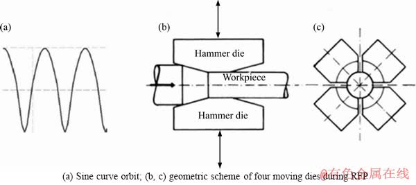
Figure 1 Schematic diagrams of motion track and hammer arrangement:
Furthermore, a deformation field resulted from a stress field induced by applied forces is due to variations of the temperature field inside the workpiece. Strain and its relationship with properties have been widely studied [2, 12, 13, 16]. SANJARI et al [12] calculated the strain distribution in RFP of tube via finite element method (FEM), and the calculation results were corresponding to the distribution of micro- hardness correctly. WU et al [15] proposed an upper model with continuous velocity field to investigate the strain inhomogeneity in RFP. Based on a simplified experimental model, LINDH et al [17] quantified the influence of redundant deformation on recrystallization kinetics and the final microstructures.
The strain inhomogeneity involves in the process, and the optimization of process conditions is traditionally a trial-and-error process based on empirical or approximate analysis, which is expensive and time-consuming [18, 19]. Currently, advanced optimization methods are widely employed in industry including the slab method and upper bound method, and numerical analysis referring to FEM simulation. However, the slab method [20-22] cannot solve the problems of forging penetration and strain inhomogeneity due to its limitations of the hypothetically uniform strain. The simplified upper bound method [23] has been also employed to investigate RFP, but strain inhomogeneity and forging penetration may be solved if only inhomogeneous deformation mode was considered in this method [24]. Furthermore, slab methods and upper bound methods [15, 25] need more efforts to provide accurate and intuitive results than FEM.
The joint of FEM and statistical method of experiment is gradually considered an efficient tool to provide accurate results of RFP. While FEM [26, 27] can predict many variables such as radial force, strain, strain rate, and temperature distribution, it is time-consuming, computationally expensive for a completed optimization procedure. Consequently, it is necessary to firstly use statistical method of the experiments (or simulations) to obtain optimal parameters prior to FEM. As an example, to optimize the strain inhomogeneity and forging force in RFP, SANJARI et al [2] proposed an optimization method with the artificial neural network (ANN) and the Taguchi method. ZHU et al [13] established the 3D rigid-plastic FEM model of the precision radial forging to evaluate the deformation quality by using the deformation homogeneity and material damage of forged products. Besides, the statistical method (Latin hypercube square design sampling method) was applied to establishing the evaluation functions from the least numbers of trials for the hollow shaft. While the statistical method and FEM have been ever applied together, there are few investigations on RFP of hollow gear shafts with variable cross sections and thickness via the methods.
To decrease the strain inhomogeneity produced during the hot RFP of a hollow stepped gear shaft (hollow shaft) for automobile, FEM and orthogonal design are jointly employed, aiming to obtain optimal combination of process parameters including the initial temperature, the rotation rate, and the radial reduction. Finally, FEM is confirmed by experimental results, and the effects of various parameters on strain fields are attempted to be analyzed.
2 Experimental methods
2.1 FEM modeling
Billets used for the production of gear shafts are designed as hollow cylindrical shape with a flange part on the base. The dimensions of the billet are 35 mm in inner diameter, 75 mm in outer diameter and 93.5 mm in length, respectively. The dimensions of the flange part are 103 mm in outer diameter and 16 mm in thickness. Because the hollow shaft had a big variation in diameters during RFP, the remesh process during simulation was employed to reduce the numbers of interruptions because of the distorted mesh. A commercial finite element software SIMUFACT was employed to model RFP and determine the thermal effects on deformation of the products. Besides, to save the computational time, the following assumptions need to be made: 1) the four hammer dies, mandrel, chuck heads are assumed to be rigid bodies without significantly losing the accuracy of model; 2) the material is not compressible and has isotropy. The billet/workpiece was meshed by using eight-node, isoparametric hexahedral element. The finite element model for the workpiece is shown in Figure 2.
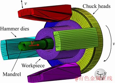
Figure 2 Schematic diagram of three-dimensional model for workpiece during RFP
Combined friction model was used based on coulomb law and shear friction types. Compared with either of these two friction types, this model could accurately simulate the friction force of the material subjected to yield stress or flow stress [1, 13]. The frictional stress is defined as  where �� is friction factor and �� is the flow stress at first and then the yield stress.
Transient heat transfer occurs by radiation, free convection and conduction during RPF in each stroke. Both the heat transfer coefficient (HTC) to the workpiece and emissivity for heat radiation to environment were set as automatic, which meant a corresponding table selected for RFP based on the thermal conductivity of the material, current pressure, etc. Nevertheless, heat coefficient to environment was constant (50 W/(m2��K)), and this value was the same for both the workpiece and the dies. The initial temperature of the dies is 200 ��C, and the initial temperature of workpiece is determined by preset temperatures. The temperature of mandrel can be stayed at a constant temperature due to its internal cavity provided for the coolant channel.
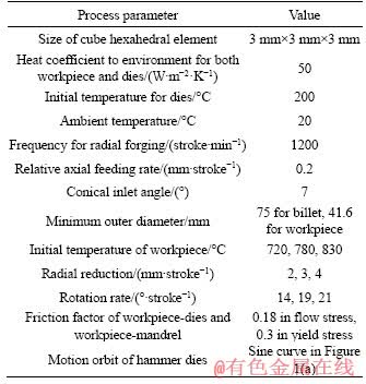
The four moving dies based on Scotch-Yoke or hydraulic press kinematics, approximately follow a sine curve (seen as in Figure 1(a)) and the curve function is y=Asin(0.157t), where A is the moving dies amplitude related to the radial reduction, and the forging frequency is 1200/min. Additionally, the rotation rate is the function of the time (t). Process parameters used in simulation are shown in Table 1.
In this study, the hollow shaft is made of the steel 27MnCr5. The material properties relevant to the thermal-mechanical simulation, such as elastic modulus, thermal conductivity, specific heat capacity, and thermal expansion coefficient, are functions of temperature and were input by the AISI standard data. To characterize the flow stress experienced by the workpiece during hot processing, a series of data concerning constant- strain-rate isothermal compression experiments were performed from the software database.
Table 1 Process parameters used in simulation
2.2 Orthogonal experimental design
Orthogonal design was employed to infer the best level combination of the initial temperature (A), the rotation rate (B) and the radial reduction (C), and estimated the influence significance of each factor on strain inhomogeneity by using inhomogeneity factor (IF).
2.2.1 Evaluation index of strain inhomogeneity
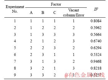
IF is defined as evaluation index, and it mainly reflects the discrete distribution level of effective strain on workpieces. The following expression consists of the effective strain variances and the average effective strains (��ave) of n nodes.
 (1)
(1)
 (2)
(2)
where ��i is the node effective strain of workpieces via FEM, n is the total node number. The lower the IF is, the more homogeneous the strain is.
Heterogeneous deformation seriously causes the residual stress of produced profiles [1]. Meanwhile, the product with uneven deformation tends to be of decreased fatigue life and increased holes and cracks [13]. To investigate the homogeneity during hot radial forging of the hollow stepped shaft, five cross-sections were selected because of their different diameters, and all nodes used in Eq. (1) are selected from these five cross sections shown in Figure 3.
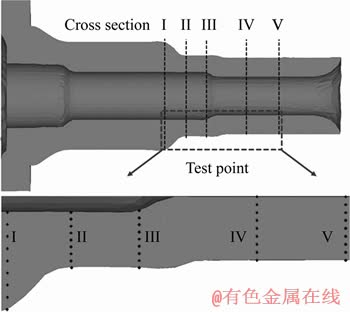
Figure 3 A schematic of five cross sections selected along radial direction for workpieces
2.2.2 Orthogonal test scheme
Due to the existence of vacant column (error) used to calculate the sum of squared error (SSE), the orthogonal table L9(34) has been employed and the factor-levels (values) as well as the orthogonal test scheme are shown in Tables 2 and 3, respectively.
To determine the Ac1 and Ac3 temperatures of this steel (Ac1, Ac3 are respectively the starting temperature and the finishing temperature of austenite formation during heating), a set of 10 mm diameter and 12 mm length samples were cut and machined from the as received billets, 2 mm grooves were processed on the upper and lower end faces so as to store lubricant. The dilatometry tests at the heating rate of 10 ��C/s were conducted and the specimens were heated to 950 ��C on the Gleeble-3500 simulator coupled a dilatometer, so as to measure the corresponding dimensional change.
Table 2 Factor-level form in orthogonal design
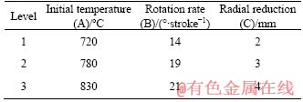
Table 3 Orthogonal test scheme
3 Results and discussion
3.1 Numeric experiment results
3.1.1 General characteristics of strain distribution
The simulated effective strain distributions of formed hollow shafts from different experiments according to Table 3 are shown in Figure 4. Along the axial direction, the head, middle, and tail parts generally subject increasing strains in order. However, the middle section located in the middle of the workpiece subjects a relatively lower strain than that of the tail part of the workpiece, which has the smallest diameter among the three sections of the workpiece. Moreover, the tail of the workpiece has very low effective strain, and it can be explained that the end surface profile (concave) exists in the tail shown in Figure 4.
The effective strain increases from the inner diameter to the outer diameter along the radial direction in Figure 4. To describe this tendency of effective strain distribution along the radial direction quantitatively, the variances of effective stain gradient with the thickness from the inner surface to the outer surface in five cross sections marked in Figure 3 are shown in Figure 5. Strain gradients along the radial direction is relatively large in RFP of the workpieces.
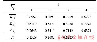
3.1.2 Intuitive result analysis
Intuitive analysis results are listed in Table 4. The number of factor is marked by j and its level is marked by i.  is the average value of evaluation index of all test results when the jth factor takes the
ith level. Rj j=1, 2, 3, 4) denotes the significant influence of the jth factor on the strain inhomogeneity. Consequently, it could be found that primary and secondary factors affecting strain inhomogeneity are B>A>C by sorting Rj with order of highest to lowest. Furthermore, small represents an excellent strain homogeneity. Accordingly, for the jth factor (column), the
  corresponding to the level i is selected as the optimal level of the factor. Ultimately, the best level combination (No. 10) is determined as A2B3C2, i.e., 780 ��C in the initial temperature, 21��/stroke for the rotation rate, and 3 mm for the radial reduction.
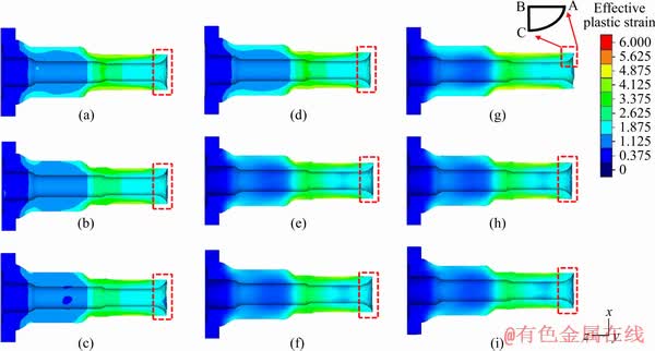
Figure 4 Effective strain distributions of hollow shafts under RFP from Experiment No. 1-9 corresponding to (a)-(i), respectively (Red dashed line shows end surface profile (concave) and inserted black symbol in (g) denotes its schematic)
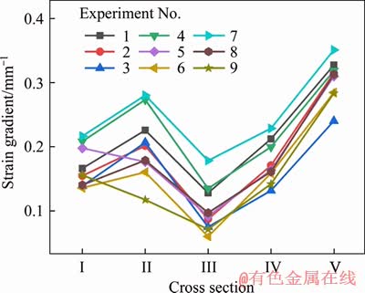
Figure 5 Strain gradients corresponding to each cross section of different experiments
Table 4 Intuitive analysis table of IF
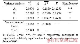
3.1.3 Variance result analysis
Because intuitive analysis results cannot distinguish whether the test results are caused by the factor level or the test errors, variance analysis results with test errors were employed and listed in Table 5. Here,  is sum of square deviation; df is the degree of freedom;
  is the mean square deviation
 F is f-distribution in mathematical statistics and reflects the significance of influence from each factor on the strain inhomogeneity.
As shown in the last row of Table 5, factor C is the least significant because of its smallest F value, while the F value of factor A is more than F0.05(2, 2), and factor B has a F value which is slightly smaller than F0.05(2, 2). Therefore, factors A and B are more significant, which are basically consistent with the intuitive analysis (B>A>C) mentioned in Section 3.1.2. Accordingly, the initial temperature and the rotation rate have a larger effect on the strain inhomogeneity.
Table 5 Variance analysis table of IF
3.1.4 Orthogonal design validation
Orthogonal design applied to this study is a scientific approach. The following equation is used to predict the value of IF under the best level combination (A2B3C2),
 (3)
(3)
where Y is the predicted value of IF under A2B3C2;  is the average value of IF under all the level combinations;
 and
and are respectively the average values of IF under the best levels corresponding to factors A, B, and C.
To verify the rationality of results predicted by the orthogonal design, the best level combination (No. 10) of those experiments was also simulated via FEM. Combined with the previous results (No. 1-9), the results of No. 10 after optimization are shown in Figure 6. The IF of No. 10 is not only the lowest among all FEM experiments but also basically consistent with the predicted value of IF, which equals 0.3962 according to Eq.(3).
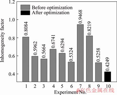
Figure 6 Inhomogeneity factor (IF) from different experiments (Experiment No. 1-9 and 10 are the results before optimization and the result of the best level combination (A2B3C2) after optimization, respectively)
3.2 Effects of processes on radial forging
3.2.1 Effect of initial temperature on strain distribution
Temperature is an important parameter in RFP because it has significant effects on deformation resistance, recrystallization of the material, and further on strain inhomogeneity.
The effective strain distributions and the temperature distributions of workpieces at different initial temperatures on cross section I are shown in Figure 7. Both the effective strain distributions and the temperature distributions gradually increase from the inner surface to the outer surface. Comparatively, both the strain distribution and outer surface at 780 ��C are relatively more homogeneous than those at other initial temperatures.
The phenomena can be attributed to two aspects. Firstly, the inner surface of workpieces has lower temperature than that of the outer surface due to the differential dissipation conditions as shown in Figures 7(d)-(f). Secondly, when the hammer dies are closed, the outer surface of the workpiece firstly contacts the hammer dies. As a result, the outer surface of the workpiece is deformed easily. Comparatively, the inner surface of the workpiece is constrained by mandrel and the friction is relatively large, so the strain on the inner surface of the workpiece is relatively small. Besides, the difference of plastic flow will inevitably lead to inhomogeneous flow of materials along the axial direction. A statistical depth of concave was employed to compare the difference of plastic flow along the axial direction, which is expressed as an absolute value  of the axial distance between Point A and Point B of the end concaves shown in the insert of Figure 4(g). The larger the absolute value is, the larger the degree of differentially plastic flow is. It can be seen from Figure 8 that the concave depth of No. 6 at 780 ��C is the lowest among three samples with variant initial temperature at rotation rate of 21��/stroke, and it is similar for rotation rates of 14 and 19��/stroke. The results suggest that the forging temperature of 780 ��C can lead to relative uniform strain.
The initial temperatures of Experiment No. 3, 6 and 9 correspond to 720, 780 and 830 ��C, respectively. The influence of the radial reduction on the strain inhomogeneity is ignored because of its least significance according to Section 3.1.2.
The dilatometry curves of this steel are shown in Figure 9, the Ac1 and Ac3 temperatures are determined as 769 and 879 ��C, respectively. The optimal initial temperature of 780 ��C is located between Ac1 and Ac3 temperatures, and the steel has austenite-ferrite microstructure at this temperature. It is analyzed that the plastic flow capability at this initial temperature can be partially retained along the axial direction and lead to a relatively uniform strain along the radial direction.
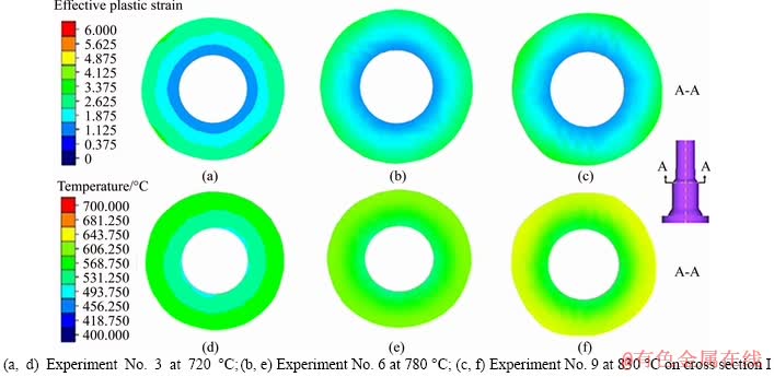
Figure 7 Radially effective strain (a-c) and temperature (d-f) distributions:
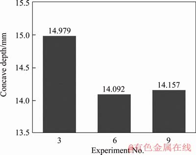
Figure 8 Depth of concave from simulated results at rotation rate of 21��/stroke
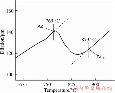
Figure 9 Dilatometry curves for 27MnCr5 at heating rate of 10 ��C/s
In a word, the workpieces are deformed differentially at different initial temperatures. Besides, this difference of deformation degree may produce different temperature rise resulting from strain energy release. The temperature rise has a different influence on subsequent deformations of workpieces at different initial temperatures in turn.
3.2.2 Effect of radial reduction on strain distribution
In general, selecting the radial reduction should ensure that the material is forged fully since the workpiece is not easily forged so that the coarse grains inside the workpiece will not be broken and many defects will not be alleviated or eliminated. Combined with the strain distribution along the radial direction of the workpiece, the variation of inner strain with the different process parameters need to be investigated separately, so as to reveal the mechanism of the corresponding influence of the process parameters on the inner strain.
The inner strain distributions along the axial direction at two different radial reductions 2 and 4 mm, are shown in Figure 10. According to the forging rule by LIU et al [28], the internal effective strain value of the workpiece is not less than 0.2. As can be seen from Figure 10, the lowest strain is also close to 1, which is considered to be completely forged. Moreover, the strain increases firstly and then decreases along the axial direction. The main reason of this phenomenon is that at the axial position of approximately 20 mm, i.e., at the position near cross section III shown in Figure 3, the inner surface of the workpiece is greatly varied so that a large shear force exists, resulting in strain peak value shown in Figure 10.
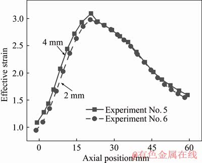
Figure 10 Effect of radial reduction on inner strain distribution at axial direction from cross section I to V for Experiments No. 5 and 6 (Strain peak value appears at axial position of approximately 20 mm, i.e., near cross section III shown in Figure 3)
Simultaneously, it is worth noting that the larger the radial reduction is, the larger the strain peak is. To relieve the influence of strain peak on inhomogeneous deformation, it is necessary to reduce the radial reduction. Nevertheless, when the radial reduction is large, the overall strain is large, and the inner part of the workpiece will generate a high strain rate to release energy, which results in a slow decrease in the internal temperature and ensures a smaller temperature gradient of the cross section. So it is not appropriate that the reduction is too small.
Besides, the effects of the radial reduction on the strains of both sides of cross section III are different, and the influence of the radial reduction on the strain of the left side (the head part containing smaller axial position) is slightly larger than that of the right side (the tail part containing larger axial position). To investigate the degree of deformation of the material, the apparent strain is defined [12]: ��apparent=ln(Ainitial/Afinal). Obviously, when ��apparent is large, the strain distribution of the right side of cross section III is weakly affected by the radial reduction. Conversely, when ��apparent is small, that is, to the left of cross section III, the radial reduction can relatively affect the strain distribution to a certain extent.
3.2.3 Effect of rotation rate on strain distribution
The inner strain distributions along the axial direction at two different rotation rates of 14 and 21��/stroke, are shown in Figure 11. The lowest strain at the inner of the workpiece is not less than the critical strain standard that is completely forged as described in Section 3.2.2., the axial positions of the strain peak values under different rotation rates shown in Figure 11 are similar to those under different radial reductions. However, the differences are that the influence of the rotation rate on the strain distribution for the left side of cross section III can be ignored and not more obvious than that for the right side of cross section III, and that the effective strain at rotation rate of 21��/stroke is smaller than that of at rotation rate of 14��/stroke on the same axial position of the right side of cross section III shown in Figure 11. The phenomena can be attributed to two aspects. To start, the workpiece on the left side of cross section III is thicker, and the influence of the rotation rate on the internal strain of the workpiece can be neglected. On the contrary, the right side of cross section III is thinner, so the rotation rate may be of a significant effect on the strain in the workpiece. In addition, the effect of temperature rise of the material caused by the larger rotation rate is not obvious, and the deformation resistance of the material on the right side is slightly large, so that the strain of the material at rotation rate of 21��/stroke is smaller than that at rotation rate of 14��/stroke on the same axial position of the right side of cross section III. Specifically, as the rotation rate of the workpiece increases, the effective strain on the inner of the workpiece gradually decreases. Because the number of forging is constant, the rotational rate is larger, the same position is not forged repeatedly, and the phenomenon of temperature rise caused by deformation is not obvious, which is beneficial to the uniform deformation of the workpieces. It can be found that when the rotation rate is large, the strain gradient (in Figure 5) of the experiments (such as Experiment No. 3, 6, and 9) is relatively small on different cross sections. Accordingly, this is advantageous for the uniformity of material deformation using larger rotation rate. Besides, compared with the rotation rate shown in Figure 11, the radial reduction shown in Figure 10 is relatively less obvious in terms of the influence on strain distribution. Moreover, we can induce that the radial reduction and the rotation rate produce larger influences on the inner strain distribution of workpieces only at small and large ��apparent, respectively.
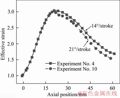
Figure 11 Effect of rotation rate on strain distribution along axial direction from cross sections I to V for Experiment No. 4 and 10 (Strain peak value appears at axial position of approximately 20 mm, i.e., near cross section III shown in Figure 3)
3.3 Experimental verification
To validate the FEM simulation mentioned, the experiments were conducted at GFM SKK-10 forging machine for RFP. The material and machining parameters in experiments were the same as those set in the simulations. The end surface profiles of the simulated and experimental workpieces are consistent in Figure 12. Comparing the outer diameters of the workpiece obtained experimentally (Figure 12) with the numerically estimated ones, its relative error is within the allowable tolerance of the factory as described in Table 6.
Besides, the position of neutral plane is a major parameter for RFP. It is essential to evaluate the performance of workpieces. In Figure 13, the positions of both Part I (sinking zone), Part II (forging zone) and Part III (sizing zone) are obtained by measuring the contact position of the hammer dies and the workpiece. For the material flow, the metal on neutral plane is only deformed radially and does not flow axially, but both sides of the neutral plane not only flow radially, but also flow axially, i.e., the left metal of the neutral plane flows to the left, and the right side metal of the neutral plane flows to the opposite. However, the exact position of the neutral surface predicted in the present study cannot be clearly seen in Figure 13. The main reasons are as follows: a) the mesh generation is not small enough; b) the neutral plane is not a planar cross section on which the material is partly subjected to shear; c) the thickness of the workpiece is not very thick. While its position is not accurately seen, it can be determined that the neutral plane is inside Part III. In contrast to the previous studies [1, 20, 23, 24], in terms of forging models about rods and tubes they have constructed, the neutral plane is often discovered in the forging zone (Part II), no matter which method is used among the upper bound method, the slab method and FEM. Nevertheless, it is worth noting that if the die entrance angle is small, and so is the frictional shear factor, the position of neutral surface will flow toward the product end (closer to the sizing zone). Moreover, for practical applications, the neutral plane near the sizing zone during RFP of workpieces can realize material toward the blank end, to prevent the material from flowing toward the product end and producing stacking damage to ensure the quality of workpiece. Consequently, the neutral plane toward the sizing zone does not deteriorate the satisfactory performance of the workpiece, but meets the requirements of precision forging instead.
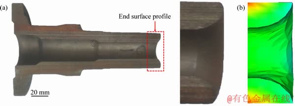
Figure 12 End surface profiles of experimental (a) and simulated (Experiment No.10) workpieces (b) during RFP
Table 6 Comparison between simulated and experimental (Experiment No.10) outer diameters on different cross sections
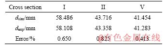
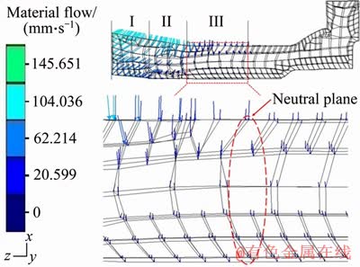
Figure 13 Material flow and neutral plane of workpiece during RFP (I, II and III denote sinking zone, forging zone, and sizing zone, respectively)
4 Conclusions
1) The simulation results have been verified experimentally, and the combination of the FE simulation and the orthogonal design method can achieve an optimal hot radial forging process in practice.
2) Strain inhomogeneity of the hollow shaft is determined by the combination of process parameters during radial process, and the optimal combination of radial forge is 780 ��C at initial temperature, 21��/stroke for rotation rate and 3 mm for radial reduction for this hollow shaft.
3) The hollow shaft is of good forging penetration among the amplitude of process parameters investigated, and its maximum strain and minimum strain distribute in the outermost and innermost zones on different cross sections, respectively. Comparatively, the initial temperature and rotation rate are of larger influences on strain inhomogeneity than the radial reduction.
4) The radial reduction and the rotation rate produce larger influences on the inner strain distribution of workpieces only at small and large ��apparent , respectively.
References
[1] FAN L X, WANG Z G, WANG H. 3D finite element modeling and analysis of radial forging processes [J]. Journal of Manufacturing Processes, 2014, 16(2): 329-334. DOI: https://doi.org/10.1016/j.jmapro.2014.01.005.
[2] SANJARI M, TAHERI A K, MOVAHEDI M R. An optimization method for radial forging process using ANN and Taguchi method [J]. International Journal of Advanced Manufacturing Technology, 2009, 40(7, 8): 776-784. DOI: https://doi.org/10.1007/s00170-008-1371-2.
[3] KHAYATZADEH S, POURSINA M, GOLESTANIAN H. A simulation of hollow and solid products in multi-pass hot radial forging using 3D-FEM method [J]. International Journal of Material Forming, 2008, 1(1): 371-374. DOI: https://doi.org/10.1007/s12289-008-0072-6.
[4] WANG K, YU T, SONG Y, LI H X, LIU M D, LUO R, ZHANG J Y, FANG F S, LIN X D. Effects of MnS inclusions on the banded microstructure in non-quenched and tempered steel [J]. Metallurgical and Materials Transactions B, 2019, 50(3): 1213-1224. DOI: https://doi.org/10.1007/s11663- 019-01532-0.
[5] SUN Z C, HAN F X, WU H L, YANG H. Tri-modal microstructure evolution of Ta15 Ti-alloy under conventional forging combined with given subsequent heat treatment [J]. Journal of Materials Processing Technology, 2016, 229: 72-81. DOI: https://doi.org/10.1016/j.jmatprotec.2015. 09.011.
[6] XIAO M L, LI F G, ZHAO W, YANG G L. Constitutive equation for elevated temperature flow behavior of TiNiNb alloy based on orthogonal analysis [J]. Materials & Design, 2012, 35: 184-193. DOI: https://doi.org/10.1016/j.matdes. 2011.09.044.
[7] YU J Q, LI Y, TENG F, LIANG JC, LIN X F, LIANG C, CHEN G Y, SUN G P. Research on the cross section forming quality of three-dimensional multipoint stretch forming parts [J]. Advances in Materials Science and Engineering, 2018, 2018: 1-11. DOI: https://doi.org/ 10.1155/2018/4265617.
[8] AMELI A, MOVAHHEDY M R. A parametric study on residual stresses and forging load in cold radial forging process [J]. International Journal of Advanced Manufacturing Technology, 2007, 33(1, 2): 7-17. DOI: https://doi.org/10.1007/s00170-006-0453-2.
[9] AZARI A, POURSINA M, POURSINA D. Radial forging force prediction through MR, ANN, and ANFIS models [J]. Neural Computing and Applications, 2014, 25(3): 849-858. DOI: https://doi.org/10.1007/s00521-014-1562-8.
[10] SAHOO A K, TIWARI M K, MILEHAM A R. Six sigma based approach to optimize radial forging operation variables [J]. Journal of Materials Processing Technology, 2008, 202(1): 125-136. DOI: https://doi.org/10.1016/j.jmatprotec. 2007.08.085.
[11] JANG D Y, LIOU J H. Study of stress development in axi-symmetric products processed by radial forging using a 3-D non-linear finite-element method [J]. Journal of Materials Processing Technology, 1998, 74(1-3): 74-82. DOI: https://doi.org/10.1016/S0924-0136(97)00252-5.
[12] SANJARI M, SAIDI P, TAHERI A K, HOSSEIN-ZADEH M. Determination of strain field and heterogeneity in radial forging of tube using finite element method and microhardness test [J]. Materials & Design, 2012, 38(6): 147-153. DOI: https://doi.org/ 10.1016/j.matdes.2012.01.048.
[13] ZHU F, WANG Z, LV M. Multi-objective optimization method of precision forging process parameters to control the forming quality [J]. International Journal of Advanced Manufacturing Technology, 2016, 83(9-12): 1-9. DOI: https://doi.org/10.1007/s00170-015-7682-1.
[14] HUMPHREYS F J, HATHERLY M. Recrystallization and related annealing phenomena [M]. 2nd ed. Elsevier, 2004: 219-224. DOI: https://doi.org/10.1016/B978-008044164- 1/50015-3.
[15] WU Y J, DONG X H. An upper bound model with continuous velocity field for strain inhomogeneity analysis in radial forging process [J]. International Journal of Mechanical Sciences, 2016, 115-116: 385-391. DOI: https://doi.org/ 10.1016/j.ijmecsci.2016.07.025.
[16] DONG L Y, LAN J, ZHUANG W H. Homogeneity of microstructure and Vickers hardness in cold closed-die forged spur-bevel gear of 20CrMnTi alloy [J]. Journal of Central South University, 2015, 22(5): 1595-1605. DOI: https://doi.org/10.1007/s11771-015-2676-6.
[17] LINDH E, HUTCHINSON B, UEYAMA S. Effect of redundant deformation on recrystallisation behaviour of copper [J]. Scripta Metallurgica Et Materialia, 1993, 29(3): 347-352. DOI: https://doi.org/10.1016/0956-716X(93) 90511-P.
[18] KO D C, KIM D H, KIM B M. Application of artificial neural network and Taguchi method to preform design in metal forming considering workability [J]. International Journal of Machine Tools & Manufacture, 1999, 39(5): 771-785. DOI: https://doi.org/10.1016/s0890-6955(98) 00055-8.
[19] QIN Xun-peng. Modelling and simulation of contact force in cold rotary forging [J]. Journal of Central South University, 2014, 21(1): 35-42. DOI: https://doi.org/10.1007/s11771- 014-1912-9.
[20] LAHOTI G D, ALTAN T. Analysis of the radial forging process for manufacturing rods and tubes [J]. Journal of Engineering for Industry, 1976, 98(1): 265-271. DOI: https://doi.org/10.1115/1.3438830.
[21] LAHOTI G D, LIUZZI L, ALTAN T. Design of dies for radial forging of rods and tubes [J]. Journal of Mechanical Working Technology, 1977, 1(1): 99-109. DOI: https://doi.org/10.1016/0378-3804(77)90016-x.
[22] GHAEI A, MOVAHHEDY M R, TAHERI A K. Study of the effects of die geometry on deformation in the radial forging process [J]. Journal of Materials Processing Technology, 2005, 170(1): 156-163. DOI: https://doi.org/10.1016/ j.jmatprotec.2005.04.100.
[23] SANJARI M, TAHERI A K, GHAEI A. Prediction of neutral plane and effects of the process parameters in radial forging using an upper bound solution [J]. Journal of Materials Processing Technology, 2007, 186(1): 147-153. DOI: https://doi.org/10.1016/j.jmatprotec.2006.12.029.
[24] WU Y J, DONG X H, YU Q. Upper bound analysis of axial metal flow inhomogeneity in radial forging process [J]. International Journal of Mechanical Sciences, 2015, 93: 102-110. DOI: https://doi.org/10.1016/j.ijmecsci.2015. 01.012.
[25] WU Y, DONG X, YU Q. An upper bound solution of axial metal flow in cold radial forging process of rods [J]. International Journal of Mechanical Sciences, 2014, 85(8): 120-129. DOI: https://doi.org/10.1016/j.ijmecsci. 2014.05.019.
[26] HSIANG S H, HO H L. Investigation of the influence of various process parameters on the radial forging processes by the finite element method (FEM) [J]. International Journal of Advanced Manufacturing Technology, 2004, 23(9, 10): 627-635. DOI: https://doi.org/10.1007/s00170-003-1646-6.
[27] RONG L, NIE Z R, ZUO T Y. 3D finite element modeling of cogging-down rotary swaging of pure magnesium square billet��Revealing the effect of high-frequency pulse stroking [J]. Materials Science & Engineering A, 2007, 464(1): 28-37. DOI: https://doi.org/10.1016/j.msea.2007.01.086.
[28] LIU X R, ZHOU X D. The forging penetration efficiency of C45 steel stepped shaft radial forging with GFM forging machine [J]. Advanced Materials Research, 2011, 154-155: 593-596. DOI: https://doi.org/10.4028/www.scientific.net/ amr.154-155.593.
(Edited by FANG Jing-hua)
���ĵ���
������ֵģ����������̽��������ղ����Կ�����Ӧ�䲻�����Ե�Ӱ��
ժҪ�����ڵ�ǰ������������Ƶ����ƣ����ÿ��Ľ��ݳ����ἰ�侶����칤��(RFP)�õ��˹㷺�о������������������Ԫģ�ͣ�ģ���˿��Ľ��ݳ�����ľ�����칤�ա����⣬��������ʵ����Ʒ�����������¶ȡ���ת�Ƕȡ�����ѹ�����ȹ��ղ����Գ��ι��̵�Ӱ�죬������Ӧ�䲻�������������۶��칤��Ӧ��IJ����̶ȡ��о�������������ϵ������СӦ��ֱ�����ڿ��Ľ��ݳ������ھ����⾶��Ե���þ���������Ź��ղ������Ϊ�¶�Ϊ780��C����ת�Ƕ�Ϊ21��/��̣�����ѹ����Ϊ3 mm��
�ؼ��ʣ�����ͣ�Ӧ�䲻�����ԣ�������ƣ�������Ϸ���������Ԫ��
Foundation item: Projects(51774054, 51974050) supported by the National Natural Science Foundation of China
Received date: 2019-03-22; Accepted date: 2019-11-13
Corresponding author: WANG Kai, PhD, Associate Professor; Tel: +86-23-65102824; E-mail: wangkai@cqu.edu.cn; ORCID: 0000- 0002-5025-467X; ZHU Zi-zong, PhD, Professor; Tel: +86-23-65102824; E-mail: zhuzizong@163.com; ORCID: 0000-0001-8985-7323
Abstract: Due to the current trend towards lightweight design in automotive industry, hollow stepped gear shafts for automobile and its radial forging process are widely investigated. Utilizing coupled finite element thermo-mechanical model, radial forging process of a hollow stepped gear shaft for automobile was simulated. The optimal combination of three process parameters including initial temperature, rotation rate and radial reduction was also selected using orthogonal design method. To examine the strain inhomogeneity of the forging workpiece, the strain inhomogeneity factor was introduced. The results reveal that the maximum effective strain and the minimum effective strain appeared in the outermost and innermost zones of different cross sections for the hollow stepped gear shaft, respectively. Optimal forging parameters are determined as a combination of initial temperature of 780��C, rotation rate of 21��/stroke and radial reduction of 3 mm.
