
J. Cent. South Univ. Technol. (2010) 17: 666-673
DOI: 10.1007/s11771-010-0538-9![]()
Effect of strain hardening and strain softening on welding distortion and residual stress of A7N01-T4 aluminum alloy by simulation analysis
YAN De-jun(�Ƶ¿�)1, LIU Xue-song(��ѩ��)1, LI Jun(���)1, 2,
YANG Jian-guo(���)1, FANG Hong-yuan(����Ԩ)1
1. State Key Laboratory of Advanced Welding Production Technology, Harbin Institute of Technology,
Harbin 150001, China;
2. Zhejiang Yinlun Machinery Company Limited, Tiantai 317200, China
? Central South University Press and Springer-Verlag Berlin Heidelberg 2010
Abstract:
The effect of strain hardening and strain softening behavior of flow stress changing with temperature on welding residual stress, plastic strain and welding distortion of A7N01-T4 aluminum alloy was studied by finite simulation method. The simulation results show that the weld seam undergoes strain hardening in the temperature range of 180-250 ��, however, it exhibits strain softening at temperature above 250 �� during welding heating and cooling process. As a result, the strain hardening and strain softening effects counteract each other, introducing slightly influence on the welding residual stress, residual plastic strain and distortion. The welding longitudinal residual stress was determined by ultrasonic stress measurement method for the flat plates of A7N01-T4 aluminum alloy. The simulation results are well accordant with test ones.
Key words:
strain hardening; strain softening, plastic strain, welding residual stress��
1 Introduction
In recent years, A7N01-T4 aluminum alloy has attracted more and more attention in aerospace and automotive industry due to its high strength, high electrical resistivity and fatigue strength, and low crack growth rate. Thus, the investigation of welded structures of A7N01-T4 aluminum ally has been developed rapidly [1-4]. Among the welding techniques, tungsten inert gas (TIG) welding is one of the main methods in joining 7000 series aluminum alloys. During welding both heating and cooling processes, the highly localized transient heat and nonlinear temperature fields result in non-uniform thermal expansion and contraction, which cause plastic deformation in the weld and near regions. Therefore, plastic strain, residual stress and distortion are permanently produced in the welded structures. As a result, the residual tensile stress may promote brittle facture, reduce the buckling strength and the fatigue life, and induce stress corrosion cracking during service [5-6].
It is known that strain hardening or strain softening behavior occurs at different temperatures. Since the welding process is an inhomogeneous and transient heating and cooling process, strain hardening or strain softening may be produced in the weld seam and near zone, which will influence the welding residual stress and welding distortion. So far, very few studies about the effects of strain hardening and strain softening behavior of aluminum alloy on the welding residual stress and welding distortion have been reported deeply [1, 7].
Since 1980s, with the advancement of computer technology, the finite element method (FEM) has become popular for analyzing welding process [8]. In this work, a three-dimensional (3D), thermo-elastic- plastic, FE model with large deformation was used to simulate the welding process. The effects of strain hardening and strain softening on the plastic strain, welding residual stress and distortion of A7N01-T4 aluminum alloy were investigated.
2 FEM model
The TIG welding process for A7N01-T4 aluminum alloy in the rolled and natural aging state was simulated based on Marc software. The welding residual stresses were determined by a coupled thermal-mechanical analysis. 3D models were adopted, allowing for 3D heat transfer in the material body and on the surface. In order to accurately capture the nonlinear geometrical behavior in the welded plate, the large deformation theory was introduced into the simulation model [9]. The thermomechanical behavior of the weld seam during welding process was simulated by coupled formulation.
The FEM model used in the simulation is shown in Fig.1. The 3D sheet model was 250 mm��150 mm�� 4 mm. The mesh in the weld seam and near zone was refined in order to gain the steep gradients of temperature and stress. Then, 8-node brick and hexahedron type elements were used in the simulation models. The total number of elements was 33 696 and the total number of nodes was 46 424. The A7N01-T4 aluminum alloy plate was laid on the welding platform and constrained by two rigid clamps during the TIG welding process. After welding, the constrained rigid clamps were removed.
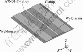
Fig.1 FEM model of welding specimen
3 Material properties
Two different material models were established based on the test results. Perfect plastic yield stress model (PM) was conventional only temperature- dependent material model. In PM, the yield stress varies with temperature during heating and cooling stage. Flow stress model (FM) was temperature- and plastic-strain- dependent material model. Strain hardening and strain softening effects were considered in FM. In FM, yield stress Y could be described as a function of temperature T and plastic strain ��p as follows:
![]() (1)
(1)
Table 1 shows the material parameters that are temperature dependent, such as elastic modulus, coefficient of thermal expansion, coefficient of thermal conductivity and specific heat capacity [10]. The tensile tests were carried out on an Instron-5500R universal testing machine at different temperatures of 20, 58, 102, 150, 200, 252, 302, 350, 400, 470, 550, 600 �� and the strain rate of 7.4��10-4 s-1. The relationship between the true stress and true strain obtained from the test data is given in Fig.2. The true stress-true strain curves show that A7N01-T4 aluminum alloy experiences different strain hardening and strain softening behaviors due to strain recovery and strain recrystallization that often occur in aluminum alloys [11-13]. It shows that strain hardening occurs in the temperature range of 20-200 �� and strain softening appears at above 252 �� in A7N01-T4 aluminum alloy. During simulation, A7N01-T4 aluminum alloy was assumed to be isotropic, linear elastic and plastic. Mises yield criterion was used to compute the thermoplastic strains and stresses. The yield stresses used in PM and FM are shown in Fig.3. It can be seen that the yield stress will increase when plastic strain occurs from 20 to 200 ��, and it would decrease when plastic strain occurs at above 252 �� in FM. However, the yield stress does not increase or decrease with the plasticity in PM.
4 Heat source
TIG welding was used. A nonaxisymmetric 3D heat source model proposed by GOLDAK et al [14] was applied to defining the moving weld arc. This model was also stated as the double ellipsoid model since the heat source was specified by two ellipsoid regions that were fore and aft parts of the source, approximated to the shape and size of the weld pool. The heat flux distribution of the double ellipsoid model is given as follows.
Table 1 Thermophysical-mechanical parameters of A7N01-T4 aluminum alloy
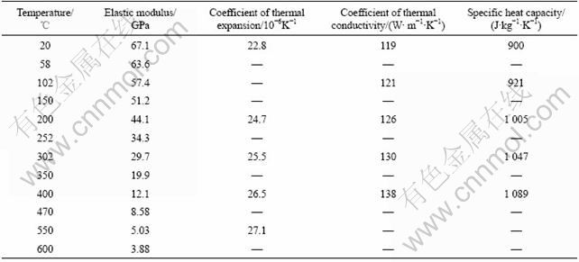
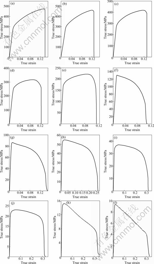
Fig.2 True stress-true strain curves at different temperatures: (a) 20 ��; (b) 58 ��; (c) 102 ��; (d) 150 ��; (e) 200 ��; (f) 252 ��; (g) 302 ��; (h) 350 ��; (i) 400 ��; (j) 470 ��; (k) 550 ��; (l) 600 ��
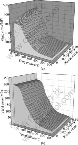
Fig.3 Yield stresses changing with temperature and plastic strain: (a) Yield stress of FM; (b) Yield stress of PM
For the fore heat source
![]()
![]() (2)
(2)
For the aft heat source
![]()
![]() (3)
(3)
where Q is the magnitude of the heat input per unit time, Q=UI; U is the voltage, U=15 V; I is the current, I= 190 A; v is the welding speed, v=3.0 mm/s; t is the welding time; ff and fr are the parameters that give the proportion of the heat deposited in the fore part and the aft part respectively, and fr+ff=2.0. The values of ellipsoidal parameters a, b, c1 and c2 are 6.0, 4.5, 7.0 and 9.0 mm, respectively, which represent heat source size relating to the characteristics of welding arc.
5 Simulation results and discussion
5.1 Welding temperature field
The weld seam undergoes complex temperature changes during welding process, which causes transient thermal stress and incompatible plastic strain (��p) in weld seam and nearby regions. The change of strain during welding process is shown as follows:
![]() (4)
(4)
where ��T is the free deformation rate, namely the thermal deformation; ��e is the external appearance deformation rate; -��p (corresponding to compressive plastic strain) and -��el (corresponding to compressive elastic strain) are the plastic and elastic deformation rates produced in the weld seam and nearby regions, respectively. The conversion from ��el to ��p augments with increasing temperature.
Fig.4 shows the transient temperature field contour of welding process when welding arc moves to the centre of sheets. It can be observed that the temperature field contour is denser in the front of molten pool and gradually becomes coarser behind away from molten pool. The temperature distributes symmetrically on both sides of the weld seam. The temperature gradient in and near the molten pool is steeper than that in other regions. As a result, the plastic strain produced in and near molten pool should be larger.
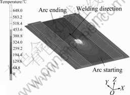
Fig.4 Temperature field contour during welding
5.2 Comparison of plastic strains
In this work, PM is determined by the temperature- dependent yield stress, while FM is related to the yield stress-dependent on both temperature and plastic strain. The longitudinal incompatible strains (plastic strain) of PM and FM across the middle sections perpendicular to the welding direction are extracted and shown in Fig.5. It can be seen from Fig.5 that the longitudinal incompatible plastic strains of PM and FM are close. The maximum longitudinal incompatible plastic strain is about 0.004 06 at node 11 372 (6.2 mm from weld central line) in FM. It can be found that the largest difference of longitudinal plastic strain between PM and FM is at node 536. The magnitude of the difference is 0.000 14, which is 3.45% of the maximum longitudinal incompatible plastic strain at node 11 372 in FM.
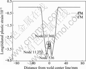
Fig.5 Longitudinal incompatible strain distribution on top surface of plate
Fig.6 shows the evolution of longitudinal plastic strain and longitudinal stress at the specific node 11 372 where the compressive longitudinal residual plastic strain is maximal. As shown in Fig.6(a), the welding thermal cycles for PM and FM overlap and the maximum temperature is 556 �� at point C when the welding time is 40.0 s. The evolution of longitudinal plastic strain is given in Fig.6(b). The weld seam metal undergoes heating and cooling processes. When the welding time is 34.0 s, the temperature reaches 180 �� at point A. The longitudinal thermal stress is larger than the yield stress of the aluminum alloy at this temperature, inducing the metal to yield and plastic strain to occur. As mentioned above, the yield stress of PM is dependent on temperature, while the yield stress of FM is dependent on both temperature and plastic strain. At 180 �� the strain hardening effect occurs in FM, leading to the smaller tensile plastic strain in FM than that in PM at point A1. At welding time of 35.5 s the temperature reaches 250 �� at point B, the yield stress falls down, and strain hardening still works in FM, thus, the difference of plastic strains between PM and FM reaches the maximum at point B1 in Fig.6(b). The plastic strain in PM is larger than that in FM. With further increasing the welding temperature, strain softening behavior occurs in FM. FM produces much more plastic strain than PM. Consequently, the difference of tensile plastic strain between FM and PM reduces. When the temperature reaches 556 ��, the two models produce the maximal compressive plastic strain at point C1. Strain softening in FM occurs in the temperature range of 250-556 ��, and the increase of compressive plastic strain in FM is larger than that in PM, so the difference of tensile plastic strain reduces. It can be seen from enlarged view of Fig.6(b) that the compressive plastic strain in FM is greater than that in PM. Finally, the longitudinal residual compressive plastic strain of FM is larger than that of PM at point D1, which results in bigger misfit in strain in weld seam for FM. Then, the longitudinal residual stress of FM is larger than that of PM, as shown in Fig.6(c).
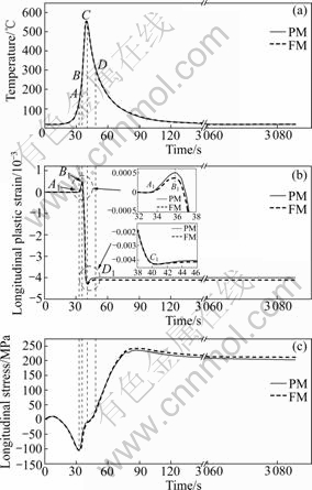
Fig.6 Evolution of welding thermal cycle (a), longitudinal plastic strain (b) and stress (c) at node 11 372
As shown in Fig. 6, the temperature gradually rises with the moving of arc. When it reaches 180 ��, the longitudinal thermal stress is larger than the yield stress, thus, the metal yields and tensile plastic strain increases. Strain hardening occurs in FM in the temperature range of 180-252 ��, which causes the increase of the difference of tensile plastic strain between PM and FM. However, when the temperature reaches 252 ��, strain softening behavior occurs in FM. FM produces more plastic strain than PM due to the strain softening effect, which results in the reduction of the difference of plastic strain between the two models. So during the TIG welding process of A7N01-T4 aluminum alloy, the metal in and near weld seam experiences the cooperant effect of strain hardening and strain softening. The two effects counteract each other, consequently, giving slight influence on the residual compressive plastic strain.
5.3 Comparison of welding residual stresses
During the fusion welding process, the weld area is rapidly heated up relative to the surrounding area, and the connecting elements are fused locally. The thermal expansion of the material caused by heat input from welding is restricted by the surrounding colder material, which gives rise to thermal stress. The local thermal stress exceeds the yield stress of the material, and the weld area undergoes compressive plastic flow. Upon cooling down, the weld area is too small compared with the surrounding area. As a result, tensile residual stress develops in the weld area and self-equilibrating compressive residual stress appears in surrounded area. Fig.7 shows the longitudinal residual stress distribution on the top surface of the plate. The peak value of longitudinal residual stress corresponds to node 11 372 due to the maximum of longitudinal plastic strain at the node shown in Fig.5. The difference of longitudinal residual stress at node 11 372 between PM and FM is 8 MPa, which is only 3.9% of the maximal longitudinal residual stress of FM. The longitudinal residual stress of PM is slightly lower than that of FM. The longitudinal residual stresses at node 536 (on the weld central line) of
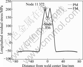
Fig.7 Longitudinal residual stress distribution on top surface of plate obtained by simulation
PM and FM are 144.562 and 144.742 MPa, respectively. The difference of longitudinal residual stress in weld central line between the two models is small. This can be related to the fact that the incompatible plastic strains of the two models are close. Although the thermal stress exceeds the yield stress at a certain temperature, the plastic strain and welding residual stress are influenced slightly due to the cooperant effect of strain hardening and strain softening.
PRESTON et al [1] used temperature history dependent yield stress model and perfect plastic yield stress model to simulate the welding residual stress and distortion in 2024-T3 aluminum alloy during TIG welding. It was suggested that the strain hardening effect occurring at high temperatures was weak, so the simulation results of different yield stress models were very close. However, ZHANG et al [7] demonstrated that the longitudinal residual stress of yield stress dependent on temperature history model is much lower than that of perfect yield stress model in 6013-T6 aluminum alloy. In this work, the longitudinal residual stresses of PM and FM for A7N01-T4 aluminum alloy during TIG welding are close. The strain hardening and strain softening work together in FM, and the two effects counteract each other, which leads to a small in residual plastic strain and residual stress between PM and FM.
The longitudinal residual stress was measured by the ultrasonic stress measuring system [15]. Fig.8 presents the test results of longitudinal residual stress. The simulation results shown in Fig.7 are accordant with the test results though the test results are slightly lower than the simulation results. The test results prove the validity of simulation results.
5.4 Comparison of welding distortions
Fig.9 shows the welding distortion of PM and FM by simulation. The distortion magnitude of PM is 0.726 mm, which is 0.098 mm less than that of FM. The difference of 0.098 mm is 13.5% of distortion magnitude of FM, and it is very small. Welding distortion is closely related to welding residual stress [16]. There is a little difference of welding distortion between PM and FM due to the small difference of longitudinal residual stress as shown in Fig.7. This can be attributed to the cooperant effect of strain hardening and strain softening during the welding process.
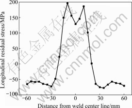
Fig.8 Longitudinal residual stress on top surface of plate obtained by test using ultrasonic stress measuring system
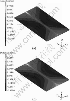
Fig.9 Welding distortion obtained by simulation using different models: (a) PM; (b) FM
Fig.10 gives the welding distortion test results. The welded plate was laid on the flat. The average welding distortion is 1.0 mm. The simulation results are consistent with the test results. Therefore, the test results also prove the validity of simulation results.
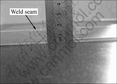
Fig.10 Welding distortion obtained by test (unit: mm)
6 Conclusions
(1) The effects of the strain hardening and strain softening of flow stress that changes with temperature and plastic strain in A7N01-T4 aluminum alloy on the incompatible plastic strains, residual stress and distortion during the TIG welding process are studied by simulation method.
(2) For A7N01-T4 aluminum alloy, the residual compressive plastic strains are affected by the strain hardening and strain softening behavior of the flow stress. The weld seam and near region mental experience strain hardening or strain softening at different temperatures during heating and cooling processes. Strain hardening occurs in the range of 180-250 �� while strain softening occurs at 252 ��.
(3) The welding residual stress and welding distortion are influenced by the strain hardening and strain softening behavior. During the welding process, the weld seam metal experiences strain hardening and strain softening effects. The two effects counteract each other, consequently, bringing slight influences on welding residual stress and welding distortion.
(4) According to the above simulation results, the effects of strain hardening and strain softening of flow stress on the incompatible plastic strain, residual stress and distortion can be neglected in TIG welding process of A7N01-T4 aluminum alloy.
References
[1] PRESTON R V, SHERCLIFF H R, WITHERS P J, HUGHES D J, SMITH S D, WEBSTER P J. Synchrotron X-ray measurement and finite element analysis of residual strain in tungsten inert gas welded aluminium alloy 2024 [J]. Metallurgical and Materials Transactions A, 2006, 37(12): 3626-3637.
[2] HYUN C Y, KIM H K. Fatigue properties of a modified 7075 aluminum alloy containing scandium [J]. Journal of Materials Science, 2010, 45(11): 3067-3072.
[3] LEE C H, KIM S W, YOON E P. Electron beam welding characteristics of high strength aluminium alloys for express train applications [J]. Science and Technology of Welding and Joining, 2000, 5(5): 277-283.
[4] HU Hui-e, ZHEN Liang, ZHANG Bao-you, YANG Li, CHEN Jun-zhou. Microstructure characterization of 7050 aluminum alloy during dynamic recrystallization and dynamic recovery [J]. Materials Characterization, 2008, 59(9): 1185-1189.
[5] DENG D. FEM prediction of welding residual stress and distortion in carbon steel considering phase transformation effects [J]. Materials and Design, 2009, 30(2): 359-366.
[6] DONG P, HONG J K, BOUCHARD P J. Analysis of residual stresses at weld repairs [J]. International Journal of Pressure Vessels and Piping, 2005, 82(4): 258-269.
[7] ZHANG Z L, SILVANUS J, LI H K, SHI Q Y. Sensitivity analysis of history dependent material mechanical models for numerical simulation of welding process [J]. Science and Technology of Welding and Joining, 2008, 13(5): 422-429.
[8] WANG S D, GOLDAK J, ZHOU J G, TCHERNOV S, DOWNEY D. Simulation on the thermal cycle of a welding process by space-time convection-diffusion finite element analysis [J]. International Journal of Thermal Sciences, 2009, 48(5): 936-947.
[9] DENG D, MURAKAWA H. Prediction of welding distortion and residual stress in a thin plate butt-welded joint [J]. Computational Materials Science, 2008, 43(2): 353-365.
[10] ZHU X K, CHAO Y J. Effects of temperature-dependent material properties on welding simulation [J]. Computers and Structures, 2002, 80(11): 967-976.
[11] LIU Xiao-yan, PAN Qing-lin, HE Yun-bin, LI Wen-bin, LIANG Wen-jie, YIN Zhi-min. Flow behavior and microstructural evolution of Al-Cu-Mg-Ag alloy during hot compression deformation [J]. Materials Science and Engineering A, 2009, 500(1/2): 150-154.
[12] LIANG Wen-jie, PAN Qing-lin, HE Yun-bin, LI Yun-chun, ZHANG Xiao-gang. Flow stress behavior of Al-Cu-Li-Zr alloy containing Sc during hot compression deformation [J]. Journal of Central South University of Technology, 2008, 15(3): 289-294.
[13] SONG Yu-quan, CHENG Yong-chun, LIU Ying. Mechanical definition and standardized measurement of the strain hardening exponent in tensile deformation [J]. Science in China: Series E, 2001, 44(2): 113-122.
[14] GOLDAK J, CHAKRAVARTI A, BIBBY M. A new finite element model for welding heat sources [J]. Metallurgical Transactions B, 1984, 15: 299-305.
[15] LU Hao, LIU Xue-song, ZHU Zheng, ZHANG Shi-ping, FANG Hong-yuan. Rapid and nondestructive measurement system for welding residual stress by ultrasonic method [J]. Chinese Journal of Mechanical Engineering, 2008, 21(5): 91-93. (in Chinese)
[16] MASUBUCHI K. Analysis of welded structures [M]. Massachusetts: Massachusetts Institute of Technology Press, 1980: 235-237.
Foundation item: Project(2007DFR70070) supported by China-Russia Government-to-Government Scientific and Technical Cooperation Foundation
Received date: 2009-10-09; Accepted date: 2010-04-11
Corresponding author: YAN De-jun, Doctoral candidate; Tel: +86-451-86418422; E-mail: yandejun_2003@163.com
(Edited by CHEN Wei-ping)
