

![]()

Trans. Nonferrous Met. Soc. China 22(2012) 1638-1646
Plasma electrolytic oxidation of zircaloy-4 alloy with DC regime and properties of coatings
CHENG Ying-liang, WU Fan
College of Materials Science and Engineering, Hunan University, Changsha 410082, China
Received 23 September 2011; accepted 5 January 2012
Abstract:
The plasma electrolytic oxidation (PEO) coatings on zircaloy-4 alloy were prepared in silicate, phosphate and pyrophosphate electrolyte systems or their combination by DC current regime. The proper processing parameters were determined and the coatings were evaluated by electrochemistry technique, micro-hardness, SEM and XRD. The results show that the coating prepared in pure silicate system is uneven and after the addition of phosphate solution, the homogeneity of the coating is still poor. The coating prepared in pure pyrophosphate electrolyte system is homogeneous, but its hardness value is low. After the addition of silicate into the pyrophosphate electrolytic system, both the uniformity and hardness of the coating are improved. The XRD results show that the phase compositions are m-ZrO2 and t-ZrO2, the addition of silicate is beneficial to the formation of t-ZrO2. The results of polarization curves show that the coatings prepared in pyrophosphate and the mixture of pyrophosphate and silicate have better corrosion resistance.
Key words:
zirconium alloy; plasma electrolytic oxidation; corrosion resistance; micro-hardness;
1 Introduction
Zirconium alloys are used for nuclear fuel cladding and structural components in water-cooled fission nuclear reactors due to their corrosion resistance, good mechanical properties and low thermal neutron absorption. Although the corrosion resistances of the alloys are relatively high, they are subject to the nodular corrosion and erosion in flowing liquid [1,2], and the waterside corrosion resistance may be a significant factor affecting their use [3-7]. The corrosion resistance of zirconium alloys can be improved by optimization of their chemistry and microstructure, including control of the size of the second phase particles [5]. The proper surface treatment, e.g., plasma electrolytic oxidation (PEO) coating, is also an effective way to improve the corrosion resistance of zirconium alloys [8,9].
Although the PEO has been widely explored for the forming of wear- and corrosion-resistant ceramic coatings on valve metals such as magnesium, aluminum and titanium [10-18], the reports about PEO surface treatment on Zr alloys are relatively few [19,20] and detailed information on the microstructure and growth processes of the coatings is scarce. So far, most of the studies of the PEO coating on zirconium alloy are performed in alkaline silicate solutions, and effect of the electrolyte composition on the properties of coatings is seldom considered.
In our previous work [21], PEO of zircaloy-4 alloy, a kind of zirconium alloy developed for applications in the nuclear industry, in silicate and pyrophosphate electrolytes with a 50 Hz square waveform AC current regime was studied in detail. However, the DC PEO on this alloy has not been reported and it may have different behaviors. In the present work, the PEO coatings formed on zircaloy-4 alloy were studied using DC regime. Different electrolyte systems of silicate, phosphate and pyrophosphate electrolyte systems or their combination are tried, the microstructure and phase composition of the corresponding coatings formed in separate electrolyte are studied. The effect of the compositions of the electrolyte on the coating formation mechanism is discussed.
2 Experimental
The zircaloy-4 alloy was obtained as plates of 5 mm in thickness in a rolled and recrystalized condition. The alloy typically comprises (in mass fraction, %) 1.50 Sn, 0.20 Fe, 0.10 Cr, Ni<0.007, Zr balance. Specimens were machined from the plate and embedded in resin, with electrical contact provided by a copper wire. The edges of the specimens were sealed with lacquer, leaving a working area of 1 cm2. The exposed working surface was ground to 4000 grit abrasive paper, degreased in ethanol, rinsed with deionized water and dried in warm air.
The electrolytes for the PEO process were prepared from analytical grade chemicals. In PEO technique, aqueous solutions of inorganic polymers, such as silicates and aluminate, phosphate, were widely used [22]. The solutions often contain NaOH or KOH to increase the electrolyte conductivity. In this study, the PEO coatings formed in silicate, phosphate, pyrophosphate and their combination were studied. The electrolyte compositions were 30 g/L Na2SiO3��9H2O + 4 g/L KOH, 30 g/L Na2SiO3��9H2O + 30 g/L Na3PO4 + 4 g/L KOH, 10 g/L Na4P2O7��10H2O + 2 g/L KOH and 10 g/L Na2SiO3��9H2O + 10 g/L Na4P2O7��10H2O.
PEO treatments were carried out at a constant DC current density of 200 mA/cm2 using a DYY-6C (600 V, 400 mA) power supplier. During the PEO experiment, the specimen was the anode and a steel plate acted as the cathode. The amount of electrolyte was 500 mL and the electrolyte was kept magnetically stirring during the PEO process. After coating, the specimens were immediately removed from the electrolyte, rinsed with deionized water and dried in a stream of warm air.
The microstructures of the coatings were analyzed by a Joel JSM6700F field emission gun scanning electron microscope (SEM). A Bruker AXS D8 Xray diffractometer (XRD) was used to examine the phase constituents of coating.
Micro-hardness measurements of the cross section of the coatings were carried out on a MHV-2000 digital microhardness tester with 1.96 N load and dwell time of 5 s.
Potentiodynamic polarization curves were carried out in a 3.5% NaCl solution (mass fraction) using a computer-monitored CHI660B electrochemical workstation to evaluate the corrosion behaviors of zircaloy-4 alloy substrate and coated samples. A three-electrode cell with the specimen as the working electrode, a saturated calomel electrode (SCE) as the reference electrode and a platinum foil as the counter electrode was employed. After 60 min immersion, the potentiodynamic electrochemical tests were carried out with a scan rate of 0.001 V/s from -500 mV versus the OCP toward more noble direction. All of the tests were carried out at room temperature.
The thicknesses of the coatings were measured by an eddy current thickness gauge (TT260, Time Company, Beijing). Twelve measurements were performed on a sample and the average and standard variations were recorded.
3 Results and discussion
3.1 Potential��time response
Figure 1 shows the potential��time responses during PEO of zircaloy-4 alloy at 200 mA/cm2 for 10 min in the different electrolytes. The potential��time responses show that the potentials rise sharply at the initial stage of PEO processing and after that the potential curves keep at a second stage in which the voltages rise slowly and in some electrolytes the voltage fluctuate violently. The initial voltage rise was attributed to the development of a barrier film on the surface by conventional anodizing [23]. Sparks occurred quickly after the beginning of PEO treatment and acoustic emission accompanied with the whole processing process.
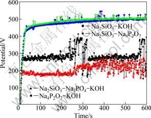
Fig. 1 Potential��time responses of PEO in 30 g/L Na2SiO3��9H2O + 4 g/L KOH, 30 g/L Na2SiO3��9H2O + 30 g/L Na3PO4 + 4 g/L KOH, 10 g/L Na2SiO3��9H2O + 10 g/L Na4P2O7��10H2O and 10 g/L Na4P2O7��10H2O + 2 g/L KOH electrolytes
In the electrolyte of 30 g/L Na2SiO3��9H2O + 4 g/L KOH, the potential at the second stage fluctuates violently, especially at the later stage. When phosphate is added in the solution, i.e., in the electrolyte of 30 g/L Na2SiO3��9H2O + 30 g/L Na3PO4 + 4 g/L KOH, the potential decreases but the amplitudes of the voltage fluctuation is still high. The potential response in 10 g/L Na4P2O7��10H2O + 2 g/L KOH is different from that in the former two electrolytes that it has a high potential and the fluctuation at the second stage is much reduced. When silicate is added into the solution, the potential response changed little.
3.2 Coatings formed in silicate solution
PEO was carried out in a 30 g/L Na2SiO3��9H2O + 4 g/L KOH solution. It was found that the PEO process in this solution is violent, with intensive sparks and loud acoustic emission. At the later stage of PEO, the number of sparks is reduced and the size of sparks is larger; the color of the sparks in this solution is orange. After the PEO treatment, the coating surfaces are very rough even through the examination of naked eyes. The thickness of the coating treated for 10 min was measured by eddy current thickness gauge. It was found that the coating has an average thickness of (73.4��13.3) ��m, where 13.3 ��m is the standard variation. This result demonstrates that the coating growth is fast but not homogenous. The surface and cross-section morphologies of the coating were analyzed by scanning electron microscopy (Fig. 2). Cracks were observed on the surface of the coating. Although the coating seems smooth in the plan view, cross section of the coating shows that it is actually uneven. In some place of the cross section, the coating protrudes like small mound (Fig. 2(c)). Figure 2(d) shows that the coating can be divided into three layers: an outer layer, an inner layer and a thin barrier layer which is located between the inner layer and the substrate. The outer layer dominates most part of the coating thickness and is compact. The inner layer is porous. It seems that gaps at the interfaces of inner layer-outer layer and inner layer-barrier layer, and these gaps are most probably formed by the accumulated pores.
3.3 Coatings formed in Na2SiO3��9H2O+Na2PO4+KOH solution
Due to the inhomogeneity of the coatings formed in the silicate solution, sodium phosphate was added into the solution and PEO process was carried out in 30 g/L Na2SiO3��9H2O + 30 g/L Na3PO4 + 4 g/L KOH. It was found that the addition of the phosphate decreased the potential level in the PEO process but the fluctuation of the potential is still high. The thickness of the coating treated for 10 min was (95.8��28.8) ��m, where 28.8 ��m is a very high standard variation. This result shows that the addition of the phosphate worsens the condition.
3.4 Coatings formed in pyrophosphate
Coatings formed in 10 g/L Na4P2O7��10H2O + 2 g/L KOH were also studied. It is found that in this electrolyte the intensity of the PEO process is lower than that in the silicate solutions, the sparks are more numerous and have a smaller size. The sparks at the early stage of PEO have a white color, but at the later stage, the color of the sparks changes into orange. The surface roughness of the coatings is reduced in this solution. The coating treated for 10 min has a thickness of (29.0��6.6) ��m. The coating treated for 60 min was also measured, and it has a thickness of (128.0��7.9) ��m. The result shows that the uniformity of the coating is improved and the coating has a growth rate of 2.1 ��m/min. The coating treated for 60 min was examined by SEM (see Fig. 3). It is shown in the plan view that the coating surface is relatively smooth but there are cracks and some nodules distributed on the surface. Figures 3(c) and (d) show the cross- section images. It can be seen that there are pores in the cross section of coating, and some cracks and loose structures exist. The micro-hardness of coating was also measured, and the hardness is HV288.7. The hardness value is slightly increased by comparing with the substrate which has a hardness of HV180.8. It can be seen from Fig. 3(c) that there are two indents left by the indenter. The size of the indent left on the coating is only slightly smaller than that left on the substrate.
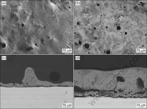
Fig. 2 SEM images of coating prepared in 30 g/L Na2SiO3��9H2O + 4 g/L KOH solution treated at 200 mA/cm2 for 10 min: (a) Secondary electron image of surface; (b) Backscattered electron image of surface; (c) Low magnification backscattered electron image of cross section; (d) Higher magnification backscattered electron image of cross section
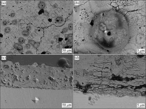
Fig. 3 SEM images of coating prepared in 10 g/L Na4P2O7��10H2O + 2 g/L KOH solution treated at 200 mA/cm2 for 60 min: (a), (b) Backscattered electron image of surface; (c) Secondary electron image of cross section; (d) Backscattered electron image of inner part of cross section
3.5 Coatings formed in mixed electrolyte of pyrophosphate and silicate
According to the above researches, the uniformity of coating formed in silicate is not satisfying and the coating formed in pyrophosphate has better uniformity but the hardness is not satisfying. So, PEO coatings were formed in the mixture of pyrophosphate and silicate, with the composition of 10 g/L Na2SiO3��9H2O + 10 g/L Na4P2O7��10H2O.
It is found that the potential��time response in this mixture solution of pyrophosphate and silicate is similar with that in the pure pyrophosphate solution. The uniformity of coatings is also improved in this solution, the coating treated for 10 min has a thickness of (29.7��3.0) ��m, although the thickness is not as high as that in the silicate solution, but the standard variation is much reduced. The thickness variation of the coatings along with the time is shown in Fig. 4. It can be seen that the coating thickness reaches 150 ��m after treatment for 60 min. There is a linear relationship between the coating thickness and PEO time and the coating has a growth rate of about 2.5 ��m/min.
The surface and the cross sections of the coating with PEO treatment for 60 min were examined by SEM. It was found that the microstructure of coatings formed in this electrolyte is much complex. Figures 5 and 6 show the surface and cross-section morphologies of the coating with 60 min PEO treatment. Figure 5(a) shows that the surface is rough, with irregular pores on the surface. Figure 5(b) shows that the surface morphology is heterogeneous in the backscattered electron mode; some part of the surface appears white while the other areas are dark. EDS analysis was performed. The results show that the white part of the coating is zirconia while the dark areas are rich in silicon, most probably silica. Figure 5(d) shows a crater-like structure which is typical in PEO coatings [24]. Figure 5(e) shows a special structure on the surface which consists of a cluster of equiaxed dendrites. This structure is also found in our previous studies on the AC PEO of zircaloy-4 alloy and is believed to be formed by the long term sparks under special solidification conditions [21]. Figure 5(f) shows the structure of the equiaxed dendrites.
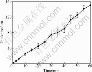
Fig. 4 Variation of coating thickness with PEO time in 10 g/L Na2SiO3��9H2O + 10 g/L Na4P2O7��10H2O solution
Figure 6 shows that the cross section of coating consists of an outer layer and an inner layer. The outer layer is condensed, and its thickness varies at different locations. Figure 6(c) shows a magnification of the outer part of the cross section of coating which consists of fine dendrites. The inner layer is relatively thick and porous. Big cavities exist between the outer layer and inner layer of the coating. Microhardness of the coating is HV549.9 which is much higher than that of the coating obtained in pyrophosphate solution. Figure 6(a) shows two indents which are left on the outer part of the coating and the substrate, respectively, and the size of the indent left on the coating is much smaller than that left on the substrate.
3.6 Phase composition of coatings
The coatings formed in different electrolytes were examined by XRD. The results are shown in Fig. 7. According to Fig.7, the main phases of the coatings are monoclinic and tetragonal zirconia, but the relative contents of the two phases are different in the coatings prepared in different electrolytes. t-ZrO2 is the main phase of the PEO coatings in the silicate solution, which can be justified from the intensity of the peak of t-ZrO2. However, in the coatings formed in pyrophosphate, and a mixture of pyrophosphate and silicate, the content of t-ZrO2 is much reduced.
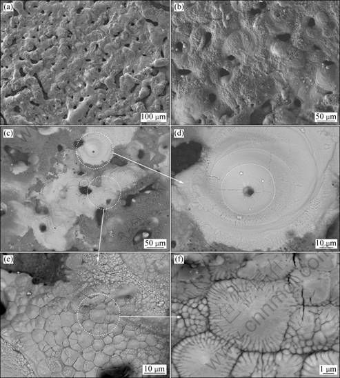
Fig. 5 SEM images of coating prepared in 10 g/L Na2SiO3��9H2O + 10 g/L Na4P2O7��10H2O solution treated at 200 mA/cm2 for 60 min: (a, b) SEM image of surface; (c) Backscattered electron image of surface; (d), (e), (f) Typical features of surface
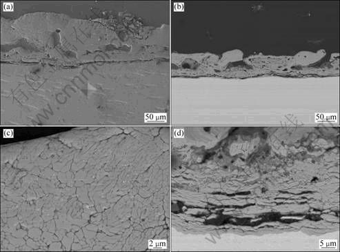
Fig. 6 SEM images of coating prepared in 10 g/L Na2SiO3��9H2O + 10 g/L Na4P2O7��10H2O solution treated at 200 mA/cm2 for 60 min: (a) Secondary electron image of cross section; (b) Backscattered electron image of cross section; (c) Outer part of cross section showing dendritic structure; (d) Inner part of cross section of coating
It is well known that the electrolyte composition is one of the key parameters that determine the morphology, composition and the macroscopic properties of PEO coatings [25-27]. Concerning the phases in the coatings, it is well known that monoclinic, tetragonal and cubic phases are the three main polymorphs of crystalline zirconia at the ambient pressure, with transition of m- to t-ZrO2 occurring at 1170 �� and from t- to c-ZrO2 occurring at 2370 ��, followed by melting at 2680-2700 �� [8]. The volume expansion caused by the phase transformations induces large stresses, which cause ZrO2 to crack upon cooling from high temperatures. The cracks observed in the cross section of the coatings are possibly caused by the phase transformation. Normally the tetragonal and/or cubic phases are high temperature phase, but they can be stabilized at room temperature by several different oxides, including MgO, Y2O3, CaO and Ce2O3, amongst others [28]. During the PEO processes, the coating material will be melted and quenched due to the high temperature of the sparks. When molten material cools, it will pass through the temperature ranges for stability of the various zirconia phases. In the case of the coatings formed in silicate electrolyte, t-ZrO2 remains in large amount. The stability of t-ZrO2 in the PEO coating formed in silicate electrolyte is possibly caused by the incorporation of silica in the coating. It has been reported [29-32] that a silica matrix has the ability to stabilize t-ZrO2 by either the particle-size effect reported by GARVIE [33] or the constraint effect reported by HEUER et al [34]. The stability of the t-ZrO2 in the PEO coatings with silica has also been reported by our previous paper [21]. Silica is believed to exist in the amorphous phase in the coatings and cannot be detected by the XRD. This is the same case in this study that there are no silica peaks in Fig. 7. However, for the coatings formed in pyrophosphate and mixed solution of pyrophosphate and silicate, there is no silica or less silica in the coating and the monoclinic zirconia dominates the phase composition of coatings.
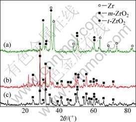
Fig. 7 XRD patterns of coatings prepared in different electrolyte systems: (a) 30 g/L Na2SiO3��9H2O + 4 g/L KOH; (b) 10 g/L Na2SiO3��9H2O + 10 g/L Na4P2O7��10H2O; (c) 10 g/L Na4P2O7��10H2O + 2 g/L KOH
3.7 Polarization curves of coatings
Figure 8 shows polarization curves of the substrate and the coatings formed in the different electrolyte solutions treated for 10 min. The corrosion current densities, corrosion potential and the breakdown potential acquired from fitting the polarization curves are listed in Table 1.
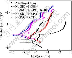
Fig. 8 Polarization curves of zircaloy-4 substrate and PEO coatings prepared in different electrolyte systems of 30 g/L Na2SiO3��9H2O + 4 g/L KOH, 10 g/L Na2SiO3��9H2O + 10 g/L Na4P2O7��10H2O, 30 g/L Na2SiO3��9H2O + 30 g/L Na3PO4 + 4g/L KOH and 10 g/L Na4P2O7��10H2O + 2 g/L KOH
Table 1 Parameters acquired from polarization curves for substrate and coatings prepared in different electrolytes
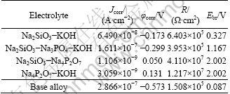
According to the results, the PEO treatment enhanced the corrosion potential of zircaloy-4 alloy. The coating acquired in the Na4P2O7-KOH solution has the highest corrosion potential of 0.131V in this experiment. The corrosion current densities for the coatings acquired in Na2SiO3-KOH and Na2SiO3-Na3PO4-KOH electrolytes are 6.490��10-8 A/cm2 and 1.611��10-7 A/cm2, respectively. These values are close to that of the substrate alloy. This demonstrates that the corrosion properties have only been enhanced a little by the PEO treatment in these two electrolytes. This phenomenon can be explained by the poor quality of the coatings. The coatings formed in these two electrolytes are coarse, which may enlarge the real surface area and possibly have more defects in the cross section. The coatings formed in pyrophosphate, and mixture of pyrophosphate and silicate have better corrosion resistance, showing corrosion current density of 1.106��10-9 A/cm2 and 3.059��10-9 A/cm2 , respectively. This is related to the better quality of the coatings acquired in this two electrolytes, for example, the coatings are more compact. There is also a parameter called the breakdown potential, which links with the pitting resistance of the materials in the chloride containing solution, so the coatings formed in pyrophosphate and the mixture of pyrophosphate and silicate have the highest breakdown potential, showing their good pitting resistance properties.
4 Conclusions
1) PEO treatment was carried out on zircaloy-4 with DC regime in silicate, phosphate, pyrophosphate electrolyte or their combination electrolytes. The microstructure and properties of coatings were evaluated by electrochemistry technique, microhardness, SEM and XRD.
2) In the pure silicate solution, the growth of the PEO coatings is non-homogenous; the addition of phosphate into the silicate solution cannot enhance the homogeneity of the coatings.
3) In the pure pyrophosphate solution, homogenous coatings can be acquired, but the microhardness of the coating is only HV288.7, while that of the substrate is HV180.8.
4) In the mixed electrolyte of pyrophosphate and silicate, both the homogeneity and microhardness of the coating are enhanced, and the microhardness of the coating is HV549.9.
5) t-ZrO2 and m-ZrO2 are two phases detected in the coatings, but their relative contents vary in different coatings. In the coatings prepared in pure silicate solution, t-ZrO2 is the main phase. In the other electrolytes, the m-ZrO2 is dominated. The stability of t-ZrO2 in the coatings formed in silicate solution is believed to be stabilized by silica.
6) Polarization curves were measured for coatings prepared in different electrolytes. The results show that the coatings prepared in pyrophosphate and the mixture of pyrophosphate and silicate has better corrosion resistance.
References
[1] MIYAKE M, UNO M, YAMANAKA S. On the zirconium�Coxygen�Chydrogen ternary system [J]. Journal of Nuclear Materials, 1999, 270(1-2): 233-241.
[2] SETOYAMA D, YAMANAKA S. Phase diagram of Zr�CO�CH ternary system [J]. Journal of Alloys and Compounds, 2004, 370(1-2): 144-148.
[3] MOTTA A T, YILMAZBAYHAN A, DA SILVA M J G, COMSTOCK R J, WAS G S, BUSBY J T, GARTNER E, PENG Q, JEONG Y H, PARK J Y. Zirconium alloys for supercritical water reactor applications: Challenges and possibilities [J]. Journal of Nuclear Materials, 2007, 371(1-3): 61-75.
[4] YILMAZBAYHAN A, BREVAL E, MOTTA A T, COMSTOCK R J. Transmission electron microscopy examination of oxide layers formed on Zr alloys [J]. Journal of Nuclear Materials, 2006, 349(3): 265-281.
[5] YILMAZBAYHAN A, MOTTA A T, COMSTOCK R J, SABOL S P, LAI B, CAI Z. Structure of zirconium alloy oxides formed in pure water studied with synchrotron radiation and optical microscopy: relation to corrosion rate [J]. Journal of Nuclear Materials, 2004, 324(1): 6-22.
[6] RAJ B, MUDALI U K. Materials development and corrosion problems in nuclear fuel reprocessing plants [J]. Progress in Nuclear Energy, 2006, 48(4): 283-313.
[7] QIN W, NAM C, LI H L, SZPUNAR J A. Tetragonal phase stability in ZrO2 film formed on zirconium alloys and its effects on corrosion resistance [J]. Acta Materialia, 2007, 55(5): 1695-1701.
[8] MATYKINA E, ARRABAL R, SKELDON P, THOMPSON G E, WANG P, WOOD P. Plasma electrolytic oxidation of a zirconium alloy under AC conditions [J]. Surface and Coatings Technology, 2010, 204(14): 2142-2151.
[9] XUE Wen-bin, ZHU Qing-zhen, JIN Qian, HUA Ming. Characterization of ceramic coatings fabricated on zirconium alloy by plasma electrolytic oxidation in silicate electrolyte [J]. Materials Chemistry and Physics, 2010, 120(2-3): 656-660.
[10] WU Hai-lan, CHENG Ying-liang, LI Ling-ling, CHEN Zhen-hua, WANG Hui-min, ZHANG Zhao. The anodization of ZK60 magnesium alloy in alkaline solution containing silicate and the corrosion properties of the anodized films [J]. Applied Surface Science, 2007, 253(24): 9387-9394.
[11] LUKIYANCHUK I V, RUDNEV V S, KURYAVYI V G, BOGUTA D L, BULANOVA S B, GORDIENKO P S. Surface morphology, composition and thermal behavior of tungsten-containing anodic spark coatings on aluminium alloy [J]. Thin Solid Films, 2004, 446(1): 54-60.
[12] RAMA KRISHNA L, SOMARAJU K R C, SUNDARARAJAN G. The tribological performance of ultra-hard ceramic composite coatings obtained through microarc oxidation [J]. Surface and Coatings Technology, 2003, 163-164: 484-490.
[13] CURRAN J A, CLYNE T W. The thermal conductivity of plasma electrolytic oxide coatings on aluminium and magnesium [J]. Surface and Coatings Technology, 2005, 199(2-3): 177-183.
[14] XUE Wen-bin, WANG Chao, TIAN Hua, LAI Yong-chun. Corrosion behaviors and galvanic studies of microarc oxidation films on Al-Zn-Mg-Cu alloy [J]. Surface and Coatings Technology, 2007, 201(21): 8695-8701.
[15] YAO Zhong-ping, JIANG Zhao-hua, SUN Xue-tong, XIN Shi-gan, LI Yan-ping. Influences of current density on structure and corrosion resistance of ceramic coatings on Ti�C6Al�C4V alloy by micro-plasma oxidation [J]. Thin Solid Films, 2004, 468(1-2): 120-124.
[16] XUE Wen-bin, WANG Chao, CHEN Ru-yi, DENG Zhi-wei. Structure and properties characterization of ceramic coatings produced on Ti-6Al-4V alloy by microarc oxidation in aluminate solution [J]. Materials Letters, 2002, 52(6): 435-442.
[17] WANG Y M, JIA D C, GUO L X, LEI T Q, JIANG B L. Effect of discharge pulsating on microarc oxidation coatings on Ti6Al4V alloy [J]. Materials Chemistry and Physics, 2005, 90(1): 128-133.
[18] MA Y, NIE X, NORTHWOOD D O, HU H. Corrosion and erosion properties of silicate and phosphate coatings on magnesium [J]. Thin Solid Films, 2004, 469-470: 472-477.
[19] NYKYFORCHYN H M, AGARWALA V S, KLAPKIV M D, POSUVAILO V M. Simultaneous reduction of wear and corrosion of titanium, magnesium and zirconium alloys by plasma electrolyte oxidation treatment [J]. Advance Materials Research, 2008, 38: 27-35.
[20] PAUPORTE T, FINNE J, KAHN-HARARI A, LINCOT D. Growth by plasma electrolysis of zirconium oxide films in the micrometer range [J]. Surface and Coatings Technology, 2005, 199(2-3): 213-219.
[21] CHENG Y L, MATYKINA E, SKELDON P, THOMPSON G, Characterization of plasma electrolytic oxidation coatings on zircaloy-4 formed in different electrolytes with AC current regime [J]. Electrochimica Acta, 2011, 56: 8467-8476.
[22] YEROKIN A L, LYUBIMOV V V, ASHITKOV R V. Phase formation in ceramic coatings during plasma electrolytic oxidation of aluminum alloys [J]. Ceramic International, 1998, 24(1): 1-6.
[23] DUAN Hong-pin, YAN Chuan-wei ,WANG Fu-hui. Growth process of plasma electrolytic oxidation films formed on magnesium alloy AZ91D in silicate solution [J]. Electrochimica Acta, 2007, 52(15): 5002-5009.
[24] PARFENOV E V, YEROKIN A L, MATTHEWS A. Impedance spectroscopy characterization of PEO process and coatings on aluminum [J]. Thin Solid Films, 2007, 516(2-4): 428-432.
[25] BLAWERT C, HEITMANN V, DIETZEL W, NYKYFORCHYN H M, KLAPKIV M D. Influence of electrolyte on corrosion properties of plasma electrolytic conversion coated magnesium alloys [J]. Surface and Coatings Technology, 2007, 201(21): 8709-8714.
[26] JIN Fan-ya, CHU P K, XU Gui-dong, ZHAO Jun, TANG De-li, TONG Hong-hui. Structure and mechanical properties of magnesium alloy treated by micro-arc discharge oxidation using direct current and high-frequency bipolar pulsing modes [J]. Materials Science and Engineering A, 2006, 435-436: 123-126.
[27] ZHANG R F, SHAN D Y, CHEN R S, HAN E H. Effects of electric parameters on properties of anodic coatings formed on magnesium alloys [J]. Materials Chemistry and Physics, 2008, 107(2-3): 356-363.
[28] EVANS A G, CANNON R M. Toughening of brittle solids by matrtensitic transformations [J]. Acta Meterialia, 1986, 34(5): 761-800.
[29] AGUILAR D H, TORRES-GONZALEZ L C, TORRES-MARTINEZ L M, LOPEZ T, QUINTANA P. A study of the crystallization of ZrO2 in the sol-gel system: ZrO2-SiO2 [J]. Journal of Solid State Chemistry, 2000, 158(2): 349-357.
[30] MONROS G, MARTI M C, CARDA J, TENA M A, ESCRIBANO P, ANGLADA M. Effect of hydrolysis time and type of catalyst on the stability of tetragonal zirconia-silica composites synthesized from alkoxides [J]. Journal of Materials Science, 1993, 28(21): 5852-5862.
[31] NAGARAJAN V S, RAO K J. Crystallization studies of ZrO2-SiO2 composite gels [J]. Journal of Materials Science, 1989, 24(6): 2140-2146.
[32] WANG S W, GUO J K, HUANG X X, LI B S. Morphological evolution of ZrO2-SiO2 composite gel and stability of tetragonal ZrO2 [J]. Materials Letters, 1995, 25(3-4): 151-155.
[33] GARVIE R C. The occurrence of metastable tetragonal zirconia as a crystallite size effect [J]. The Journal of Physical Chemistry, 1965, 69(4): 1238-1243.
[34] HEUER A H, CLAUSSEN N, KRIVEN W M, RUHLE M. Stability of tetragonal ZrO2 particles in ceramic matrices [J]. Journal of the American Ceramic Society, 1982, 65(12): 642-650.
�-4�Ͻ��ֱ�������ӵ��������Ĥ�������
��Ӣ������ ��
���ϴ�ѧ ���Ͽ�ѧ�빤��ѧԺ����ɳ 410082
ժ Ҫ���ڹ����Ρ������Ρ��������λ����ϵ��Һ�ж��-4�Ͻ���е����ӵ��������ͨ��ʵ��ȷ�����ʵĹ��ղ����������õ绯ѧ��������Ӳ�ȡ�SEM��XRD�ȼ�����Ĥ�����ܽ��б���������������ڴ��Ĺ����ε��Һ�еõ���Ĥ��ܲ����ȣ��������������κ�Ĥ���������Ȼ�ܲ�ڽ���������ϵ�еõ���Ĥ��ȽϾ��ȣ���Ӳ�ȵ͡��ڽ���������ϵ�����ӹ����κ�Ĥ��ľ����Ժ�Ӳ�ȶ��õ����ơ�XRD���������Ĥ�����Ҫ�ɷ�Ϊ��б����ﯺ��ķ�����ﯡ����ӹ����κ��������ķ�����ﯵ��γɡ��������߽���������ڽ��������Լ���������������λ����ϵ�еõ���Ĥ����н�ǿ����ʴ�ԡ�
�ؼ��ʣ�ﯺϽ𣻵����ӵ����������ʴ�ԣ���Ӳ��
(Edited by LI Xiang-qun)
Foundation item: Project (51071066) supported by by the National Natural Science Foundation of China; Project (531107040029) supported by the Fundamental Research Fund for the Central Universities, China; Project supported by the Development of Youth Teachers of Hunan University, China
Corresponding author: CHENG Ying-liang; Tel: +86-13036798588; E-mail: chengyingliang@hnu.edu.cn
DOI: 10.1016/S1003-6326(11)61367-8
Abstract: The plasma electrolytic oxidation (PEO) coatings on zircaloy-4 alloy were prepared in silicate, phosphate and pyrophosphate electrolyte systems or their combination by DC current regime. The proper processing parameters were determined and the coatings were evaluated by electrochemistry technique, micro-hardness, SEM and XRD. The results show that the coating prepared in pure silicate system is uneven and after the addition of phosphate solution, the homogeneity of the coating is still poor. The coating prepared in pure pyrophosphate electrolyte system is homogeneous, but its hardness value is low. After the addition of silicate into the pyrophosphate electrolytic system, both the uniformity and hardness of the coating are improved. The XRD results show that the phase compositions are m-ZrO2 and t-ZrO2, the addition of silicate is beneficial to the formation of t-ZrO2. The results of polarization curves show that the coatings prepared in pyrophosphate and the mixture of pyrophosphate and silicate have better corrosion resistance.
