
J. Cent. South Univ. (2012) 19: 2386-2393
DOI: 10.1007/s11771-012-1286-9![]()
Cavity noise sensitivity analysis of tire contour design factors and application of contour optimization methodology
KIM Seong-rae1, SUNG Ki-deug1, LEE Dong-woo2, HUH Sun-chul3
1. NEXEN Tire Corporation 30, Yusan-Dong, Yangsan-Si, Kyungnam 626-230, Korea;
2. Division of Automotive and Mechanical Engineering, Changwon Moonsung University, 91,
Doodae-dong, Changwon-si, Kyungnam 641-771, Korea;
3. Department of Energy and Mechanical Engineering, Institute of Marine Industry, Gyeongsang National University,
Cheondaeguk-Gil 38, Tongyeong, Gyeongnam 650-160, Korea
? Central South University Press and Springer-Verlag Berlin Heidelberg 2012
Abstract:
Cavity resonance noise of passenger car tires is generated by interacting excitation between a tire structure and the fill gas (air), and generally lies in a frequency range of 200-250 Hz. As such, this noise is strongly perceived and may be a serious source of driver annoyance. Thus, many studies regarding the cavity noise mechanism and its reduction have already been conducted. In this work, a vibro-acoustic coupled analysis was conducted between a tire structure and air cavity. Using this analysis, we can more accurately simulate the tire noise performance in the region of the cavity resonance frequency. An analysis of the effects of variation of tire contour design factors was conducted, using design-of-experiments methods. Finally, a multi-objective optimization was performed using in-house codes to reduce the cavity noise level while minimizing the loss of other performances, such as diminished ride comfort and handling caused by the variations of contour. As a result of this optimization, an optimized contour shape was derived, which satisfied the multi-objective performances.
Key words:
1 Introduction
The internal air cavity of the tire is capable of supporting the development of standing waves. These standing waves will occur at a number of harmonically related frequencies, in the range of 200-250 Hz for passenger tires. The standing waves can interact with the wheel and transmit vibrational energy through the suspension and can be re-radiated as acoustic disturbances in the passenger compartment. This problem has received considerable attention of tire and vehicle engineers, and it is an important consideration when optimizing the ride performance of a tire/vehicle system [1-2]. The simple analytical model using the structural/acoustic coupling matrix was developed by GUNDA et al for more accurate results [3]. YAMAUCHI and AKIYOSHI studied the interior road noise caused by the resonance between a tire and a wheel [4]. Kim and JEONG attached microphones to the inner-cavity for an acoustic model test [5].
In this work, we considered the acoustic coupling problem between a tire structure and its cavity. First, the application of vibro-acoustic coupled analysis to the cavity noise computation is described. The finite element method (FEM) and the indirect boundary element method (IBEM) were used as the numerical solvers. Then, the cavity noise sensitivity analysis of tire contour design factors was conducted using the design-of- experiments. Finally, a multi-objective optimization was performed using in-house codes to reduce the cavity noise level while minimizing the loss of other performances, such as diminished ride comfort and handling caused by the variations of contour.
2 Theoretical framework
2.1 Tire cavity resonance
Figure 1(a) shows that the fundamental cavity mode and axisymmetrical tire exhibit a single acoustic wavelength around the tire in patch free condition. There is one maximum and one minimum pressure point on opposite side of the tire. Nodal points are located midway between the high and the low pressure points. When the tire is loaded, the footprint introduces a perturbation and the axisymmetric mode is split into two modes. The longitudinal mode occurs at a slightly lower frequency than the vertical mode, as shown in Figs. 1(b) and (c).
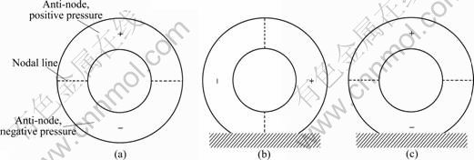
Fig. 1 Tire cavity resonance: (a) Axisymmetric cavity mode; (b) Fore/after cavity mode; (c) Vertical cavity mode
The frequency of the cavity resonance is defined by the tire and rim size, as well as the speed of sound in the acoustic medium that inflates the tire. A simplified equation for the cavity resonance frequency f is
![]() (1)
(1)
where c is speed of sound in the gas inflating the tire; l is length of the cavity, D is outer diameter of the cavity, and d is inner diameter of the cavity. Typical resonance frequencies for most passenger car tire/rim assemblies are in a range between 200 and 250 Hz, whereas the frequencies are approximately 150 Hz for heavy truck tires.
2.2 Vibro-acoustic problems
For coupled vibro-acoustic problems, an acoustic and a structural problem must be solved simultaneously to include the mutual coupling interaction between the fluid pressure and the structural deformation. The finite element method is usually applied for the prediction of the structural response, while the direct or indirect boundary element method can be applied for the prediction of the acoustic response.
As for uncoupled acoustic problems, a fundamental distinction should be made between interior and exterior coupled vibro-acoustic systems depending on whether the acoustic domain is bounded or unbounded.
In an interior coupled vibro-acoustic system, the fluid is comprised of a bounded acoustic domain V, of which the boundary surface ��a contains an elastic structural surface ��a (��a=��s![]() ��p
��p![]() ��v
��v![]() ��z), as shown in Fig. 2.
��z), as shown in Fig. 2.
In an exterior coupled vibro-acoustic system, the fluid is comprised of an unbounded acoustic domain V, which is the space between a boundary surface ��a, containing an elastic structural surface ��s, and a boundary surface ����, located at infinity, as shown in Fig. 3.

Fig. 2 Interior coupled vibro-acoustic system of tire/wheel assembly

Fig. 3 Exterior coupled vibro-acoustic system of tire/wheel assembly
For coupled vibro-acoustic problems, an acoustic and a structural problem must be solved simultaneously to include the mutual coupling interaction between the fluid pressure and the structural deformation. A commonly used technique for interior coupled problems and exterior coupled problems with a closed boundary surface is the coupled FE/BE model. In this model, a structural FE model, which is based on a displacement approximation, is coupled with a BE model. The structural and normal fluid displacement continuity at the fluid-structure coupling interface is taken into account by a transformation matrix T, which relates the fluid normal velocity values vni at the nodes of the acoustic BE mesh to the displacement components wi at the nodes of the structural FE mesh:
{vni}=j��T��{wi} (2)
Assuming that the whole boundary surface of the coupled vibro-acoustic system consists of an elastic structural surface, the non-symmetric coupled FE/direct BE model becomes
![]() (3)
(3)
The matrix Lc results from the acoustic pressure loading on the elastic structure. For coupled vibro-acoustic problems with an open boundary surface or combined interior/exterior coupled vibro-acoustic problems, a structural FE model can be coupled with an indirect BE model. Assuming that the whole boundary surface of the vibro-acoustic system consists of an elastic structural surface, the symmetric coupled FE/indirect BE model becomes
 (4)
(4)
The coupling matrix Lc and its transpose result from the acoustic pressure loading on both sides of the elastic structure, and the structural and fluid displacement continuity at the fluid-structure coupling interface.
2.3 Vibro-acoustic coupled analysis
2.3.1 Structural model
A structural model and harmonic finite element analysis of a tire model driven by a radial force at one point was performed. The model was based on a radial 215/60R16 tire, and the tire FE model was implemented in ABAQUS. A static inflation pressure of 220.64 kPa was applied to the inner surface of the tire and a harmonic radial point force was applied at the ground. The structural harmonic analysis was started at 0 Hz and was performed over a range of 500 Hz at constant frequency intervals of 0.5 Hz. A model damping ratio of 0.03-0.05 was added to each mode, but the loss factors of rubber materials were not modeled. The displacements and accelerations at each node on the tire surface were then calculated. Then, for a mapping of the two geometrical models, the maximum distance algorithm was used, which establishes relation between the structural mesh and the acoustic mesh. The source model, structural mesh part, has about 40 000 nodes and the target model, acoustic mesh part, has about 3 500 nodes. The data of the source nodes are transferred to the target node by Eq. (5). This means that the target node takes the data from surrounding N nodes in inverse proportion to the distance. Figure 4 shows the comparison of the two models, a solid and a surface mesh model.
 (5)
(5)

Fig. 4 Comparison of structural solid mesh and acoustic surface mesh: (a) Solid mesh model; (b) Surface mesh model
A data transfer analysis was conducted, that is, the structural tire responses at each node were applied from a solid element model to a surface element model. This surface model will be used in the next step of FE/BE coupled analysis.
2.3.2 Acoustic model
The acoustic interior and exterior analysis for the tire model described above was performed by using the indirect boundary element method (IBEM), available within LMS Virtual.Lab. A cavity surface model was also employed in order to couple an acoustic model with a structural model. Figure 5 shows the vibro-acoustic model including a structural and an acoustic cavity model. It also shows the hemispherical field point mesh for predicting its sound power level. The hemispherical field point mesh comprising 19 field points was defined in accordance with ISO3744. Another field point mesh is modeled in an inner cavity. The reason for modeling these field points is to study the sound pressure distribution in the cavity. The symmetry plane was added to this model to account for ground reflection. The reflecting plane was modeled to be rigid.
2.3.3 Results of cavity noise analysis
The validation of the FE tire model was conducted through a comparison with the modal test results. Figure 6 shows the comparison of FRF in the radial direction at the driving point between them. We could indentify that this analysis result agrees with the test result up to 500 Hz. Such a correct FE model has an important role to insure the precision of the following acoustic analysis.
Figure 7 shows the interior sound pressure distributions in the tire cavity. These are not acoustic modes but pressure distributions generated by input force (white noise excitation). The first resonance frequency of the cavity is about 217 Hz and the second resonance frequency is about 429 Hz. Interior sound pressure level is maximized at these frequencies. Figure 8 represents the interior SPL at the MC point according to frequency.

Fig. 5 Tire/cavity model and field points used in vibro-acoustic analysis: (a) Tires acoustic cavity model; (b) Hemispherical field model
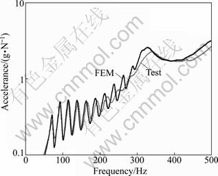
Fig. 6 Comparison of structural response between a FE model and test model
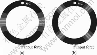
Fig. 7 Interior sound pressure distributions in tire cavity: (a) 1st cavity resonance region (217 Hz); (b) 2nd cavity resonance region (429 Hz)

Fig. 8 Interior sound pressure level calculated at MC point
Figure 9 shows the exterior sound power level calculated at the ISO field points. This represents the model frequency performance of a tire structure and an acoustic cavity since we applied the white noise excitation. Even if different types of excitations such as road surface force are applied to the tire structure, the sound radiation performance in the cavity resonance region will be simulated in the same manner.

Fig. 9 Acoustic power calculated at ISO field points
2.4 Sensitivity analysis
2.4.1 Design of experiments
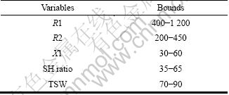
Generally, it is a well known truth that the cavity noise level of a tire is profoundly linked to its bulk. This means that we can control the cavity noise by changing contour design factors such as tire width, aspect ratio, overall diameter and so on. These contour design changes also affect other structural vibration noises in a low/middle frequency range including the cavity noise [6]. In this work, several design factors are employed to control the cavity noise level in the same size (215/60R16). Tire section width, overall diameter, and rim diameter are all held constant. Figure 10 shows the contour design factors used in this sensitivity analysis. R1 is the radius of curvature of the tread center band. Another contour can be constructed from the end of the contour following the R1 to the shoulder band. The radius of curvature of this contour is R2. X1 is a straight distance from the center line of a section to the intersection point between R1 and R2. The TSW represents the tire section width, and the SH ratio is the proportion of the height of total section to the height of upper part.

Fig. 10 Tire contour design factors
Table 1 presents the levels of each design factor. We have decided the appropriate dimension to be within the range of feasible drawing, because these five design factors are not independent to each other.
Table 1 Level of each design factor

2.4.2 Results of sensitivity analysis
The result of the cavity noise sensitivity analysis by using the design-of-experiments method is presented in Fig. 11. We could see that all the five design factors are contributory to the cavity noise within the 95% confidence interval. Among them, the factor, X1, makes the most significant contribution, and R2 is opposed to that. Then the results of the sensitivity analysis of tire contour design factors show that the cavity noise level depends largely on the tread curvature when the conditions are in the same size.
3 Multi-objective optimization
3.1 Problem definition
As mentioned above, the cavity noise sensitivity analysis according to variation of the contour design factors was conducted using tire models which have the same size. This was intended to maintain other performances such as ride comfort and steering precision to prevent a seismic change in them when designing a low noise tire. Therefore, in this work, the multi-objective optimization was conducted to improve the ride comfort and handling performance as well as the cavity noise performance. In the frequency range of 0.5-5 Hz, the tire/vehicle system behaves as a group of masses connected together by springs and dampers, i.e. rigid body motions. At each corner of the vehicle, it is possible to define a quantity known as the ��ride rate��, which is the effective spring rate of the suspension and the tire:
![]() (6)
(6)
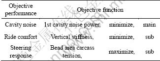
For good ride performance, the resonance frequency of the tire/vehicle system should be as low as possible [7-8]. That is, the more the tire has lower vertical stiffness in a ride stroke direction, the more the ride performance is improved in these frequency regions. Generally, stiffer carcass tension of the bead area or stiffer belt tension makes the steering response better [9]. Thus, bead area tension was chosen as the factor representing the steering precision performance. Finally, the objective functions chosen for this optimization are the first cavity noise power, vertical stiffness, and carcass tension at bead area, as given in Table 2. Cavity noise is a main objective function, and the others are sub objective functions.
We have studied the tire contour optimization methodology and developed the in-house codes using the genetic algorithm and regression analysis [10-11]. The flowchart of this optimization algorithm is shown in Fig. 12. First of all, the orthogonal array is built based on the design-of-experiments. Then the simulations to each model are performed to obtain the regressions classified by each objective function [12]. Afterward, we can derive the optimized contour by executing the program with a built-in genetic algorithm. This process also includes the constraint method to solve pareto problems [13]. Lastly, the derived contour is checked whether it is satisfied with any other constraints such as intuition or manufacturing constraint. The dimension constraints of each contour design factor used in optimization procedure are represented in Table 3.

Fig. 11 Results of cavity noise sensitivity analysis classified by tire contour design factors: (a) R1, (b) R2; (c) TSW; (d) SH ratio; (e) X1; (f) Contribution
Table 2 Objective performances and functions
3.2 Results of optimization
The results of optimization and comparison with the results of the initial contour model are summarized in Table 4, and then comparison of the two contour images is shown in Fig. 13. The main objective function, the first cavity noise power, in this work is decreased by 30% compared with the initial model. This means that the peak value at the first cavity resonance frequency (217 Hz) is reduced considerably despite of size limitations such as same section width, overall diameter, and rim diameter. The cavity noise power is also represented in terms of a weighted decibel as shown in Table 4. The optimized model shows a 1.4 dB reduction in radiated acoustic power level. We could also see that the sub-objective functions, vertical stiffness and carcass tension, have an improvement ratio within 5%. This means that other performances related to these two sub-objective functions, ride comfort and steering response, are slightly improved or maintained compared with the initial model after the optimization.

Fig. 12 Flowchart of optimization algorithm
Table 3 Bounds for design variables
Figures 14 and 15 show the comparison of acoustic response between the initial contour model and the optimized contour model. We could see that the structural frequencies of the optimum model lie lower than the initial one because the optimum model is designed to have lower vertical stiffness for improving ride performance. However, we could indentify that the cavity resonance frequencies are constant.
Table 4 Comparison of objective functions between initial and optimized model


Fig. 13 Comparison of contour between initial and optimized model

Fig. 14 Comparison of interior sound pressure level between initial contour and optimized contour

Fig. 15 Comparison of exterior acoustic power level between initial contour and optimized contour
4 Conclusions
1) The application of the vibro-acoustic coupled analysis to the tire-cavity resonance problem is available for representing the weak coupling phenomenon between them. Interior sound pressure and exterior sound power are calculated at once by the FEM/IBEM solution, and they are employed as an index for evaluating the cavity noise performance.
2) The results of the sensitivity analysis of tire contour design factors show that the cavity noise level depends largely on the tread curvature in condition of the same size.
3) The optimized tire contour model is derived using a multi-objective optimization algorithm. The objective functions are cavity noise level, vertical stiffness, and carcass cord tension. We could identify that the algorithm provides us with the improved tire contour throughout various performance such as cavity noise, ride comfort and handling.
References
[1] SCAVUZZO R W, CHAREK L T, SANDY P M, SHTEINHAUZ G G. Influence of wheel resonance on tire cavity noise [R]. Warrendale: SAE, 1994.
[2] SAKATA T, MORIMURA H, IDE H. Effects of tire cavity resonance on vehicle road noise [J]. Tire Science and Technology, TSTCA, 1990, 18(2): 68-79.
[3] GUNDA R, GAU S, DOHRMANN C. Analytical model of tire cavity resonance and coupled tire/cavity modal model [J]. Tire Science and Technology, TSTCA, 2000, 28(1): 33-49.
[4] YAMAUCHI H, AKIYOSHI Y. Theoretical analysis of tire acoustic noise and proposal of improvement technique [J]. JSAE Review, 2002, 23: 89-94.
[5] KIM Y W, JEONG K S. Experiments on air cavity resonance of radial tire for passenger car [R]. Seoul: The Korean Society of Automotive Engineers, 2006.
[6] YUM Kiho, HONG Kwan-woo, BOLTON J S. Influence of tire size and shape on sound radiation from a tire in the mid-frequency region [R]. Warrendale: SAE, 2007.
[7] GILLESPIE T D. Fundamentals of vehicle dynamics [R]. Warrendale, PA: Society of Automotive Engineers, 1992.
[8] GENT A N, WALTER T D. The pneumatic tire national highway traffic safety administration [R]. Washington D.C.: U.S. Department of Transportation, 2005.
[9] YAMAGISHI K, TOGASHI M, FURUYA S, TSUKAHARA K, YOSHIMURA N. A study on the contour of the radial tire: Rolling contour optimization theory-RCOT [J]. Tire Science and Technology, TSTCA, 1987, 15(1): 3-29.
[10] KIM S R, LEE D W, SUNG K D, CHO S S, JOO W S, CHO C T. The development of intergrated optimum contour design system to satisfy multi-performance of the tire [C]// Presentation at the 2006 Tire Society Meeting. Akron: 2006: 25.
[11] LEE D W, KIM S R, HONG S H, CHO S S, JOO W S, CHO C T. A study on the shape optimization of tire using G.A. [R]. The Korean Society of Mechanical Engineers, 2006.
[12] SONG B S, LEE J W, KIM S R, SUNG K D. A study on the comparison of approximation models for multi-objective design optimization of a tire [R]. Seoul: The Korean Society of Automotive Engineers, 2011.
[13] KIM J K, BAE T S, LEE D W, LEE K H. Structural design of a tire contour based on approximation model [C]// Annual Conference Proceeding of KSAE, Songdo, 2009: 1075-1082.
(Edited by HE Yun-bin)
Received date: 2011-10-12; Accepted date: 2012-02-29
Corresponding author: HUH Sun-chul, Assistant Professor; Tel: +82-55-772-9111; Fax: +82-55-772-9119; E-mail: schuh@gnu.ac.kr
Abstract: Cavity resonance noise of passenger car tires is generated by interacting excitation between a tire structure and the fill gas (air), and generally lies in a frequency range of 200-250 Hz. As such, this noise is strongly perceived and may be a serious source of driver annoyance. Thus, many studies regarding the cavity noise mechanism and its reduction have already been conducted. In this work, a vibro-acoustic coupled analysis was conducted between a tire structure and air cavity. Using this analysis, we can more accurately simulate the tire noise performance in the region of the cavity resonance frequency. An analysis of the effects of variation of tire contour design factors was conducted, using design-of-experiments methods. Finally, a multi-objective optimization was performed using in-house codes to reduce the cavity noise level while minimizing the loss of other performances, such as diminished ride comfort and handling caused by the variations of contour. As a result of this optimization, an optimized contour shape was derived, which satisfied the multi-objective performances.
