
J. Cent. South Univ. Technol. (2011) 18: 1969-1975
DOI: 10.1007/s11771-011-0930-0![]()
Continuity control method of cutter posture vector for
efficient five-axis machining
HWANG Jong-dae, KIM Sang-myung, JUNG Hyun-chul, JUNG Yoon-gyo
School of Mechatronics, Changwon National University, Changwon 641-773, Korea
? Central South University Press and Springer-Verlag Berlin Heidelberg 2011
Abstract:
During five-axis machining of impeller, the excessive local interference avoidance leads to inconsistency of cutter posture, low quality of machined surface and increase of processing time. Therefore, in order to improve the efficiency of five-axis machining of impellers, it is necessary to minimize the cutter posture changes and create a continuous tool path while avoiding interference. By using an MC-space algorithm for interference avoidance, an MB-spline algorithm for continuous control was intended to create a five-axis machining tool path with excellent surface quality and economic feasibility. A five-axis cutting experiment was performed to verify the effectiveness of the continuity control. The result shows that the surface shape with continuous method is greatly improved, and the surface roughness is generally favorable. Consequently, the effectiveness of the suggested method is verified by identifying the improvement of efficiency of five-axis machining of an impeller in aspects of surface quality and machining time.
Key words:
1 Introduction
Five-axis machine has not only three linear feed axes but also two rotational feed axes. So products of various fields can be efficiently machined by free control of the cutter axis vector. This flexible accessibility makes it possible to produce core parts for various industries such as airlines, space, turbo machines, and molds. However, in order to safely utilize this five-axis machine while increasing machining efficiency, tool path should be created in a simple fashion with consideration of the interference between the tool and machining surfaces. However, most CAM S/W on the current market locally process avoidance on the parts where interference occurred, and then cutter posture is changed rapidly and unnaturally, which can become a cause of overcut, undercut, or low surface quality. Moreover, discontinuous changes of cutter posture become a cause of processing time increase by reducing rotational feedrate.
Especially, a part such as an impeller among five-axis machining parts is a very high value product. But the gap between its blades is so narrow and deep that interference between tool and neighboring surfaces frequently occurs. So, the problem of interference avoidance is a very important factor. Also, because the efficiency can be maximized when fluids smoothly flow on the blade and hub surface due to the characteristics of the impeller, a high quality of the machined surface is required. During five-axis machining of these impellers, the excessive local interference avoidance leads to inconsistency of cutter posture, low quality of machined surface and increase of processing time. Therefore, in order to increase the efficiency of five-axis machining of impellers, it is necessary to minimize the cutter posture changes and create continuous tool path while avoiding interference. There are several studies about interference avoidance processes that secure safety. Some studies treated the interference problem as an optimization problem using cusp height [1-2]; another studies used curvature as a differential geometrical concept [3-7]. However, these studies consider only the error accumulation problem due to the approximation and angle of rotation, but do not sufficiently use advantages of tilting angle changes. There were studies [8-10] relating to these interference avoidance processes, which have utilized configuration-space (C-space) and similar concepts when creating machining data. But these later studies are limited to three-axis machining or suggest passive interference avoidance methods when cutter posture point is detected in the interference area, and surface roughness gets worse due to rapid cutter posture changes.
Most existing studies about tool interference avoidance focused on convenience and ease of interference avoidance. However, problem occurred due to surface quality declining because of rapid cutter posture changes on tool path after interference avoidance. MORISHIGE and WAKAYAMA [11] considered cutter posture continuity to improve the surface quality, but the results are hard to apply due to its complexity.
Therefore, the purpose of this work is to secure safety and improve surface quality by creating a tool path that actively avoids interference, minimizes changes of cutter posture vector considering cutter posture continuity, and reduces machining time for models with high interference, such as impellers, and improves the efficiency of five-axis machining of impellers. So, a continuous control method of cutter posture changes is suggested, and the difference from the cutter posture changes created by the conventional method is shown. A cutting experiment is performed to compare the influences of the differences of cutter posture changes on the increase of five-axis machining efficiency in aspects of surface quality and machining time to verify the validity of the suggested method.
2 Interference avoidance by MC-space algorithm
As shown in Fig.1, cutting point data of the cutter contact point, C, where a tool comes into contact with a work piece, are set up in a local coordinate system with a normal vector, N, of machined surface as the z axis, tool feed direction vector F as the x axis, and cross product of F��N as the y axis. Cutter location (CL) data create the tool path consisting of O, which is an offset point, C, in the direction of the normal vector N of the surface with the distance of the cutter radius, R, and cutter posture vector (CPV), T.
The angle between N and T is an angle of inclination, ��, and the rotating angle around the z axis is the angle of rotation, ��; with these two parameters, T can be changed to the cutter posture point (CPP), P, as shown in Fig.1(b), which is two-dimensional C-space [5]. C-space easily identifies the existence of interference with neighboring obstacles by mapping CPV, T in the real space as CPP, P in the two-dimensional C-space and collision surface (CS) in the real space as collision area (CA) in the two-dimensional C-space. When interference occurs, the cutter posture vector that avoids interference in real space can easily be obtained by allowing CPP in the interference area to move to the free area.
In previous studies [12-15], the method shown in Fig.2 was suggested, which transforms points, including not only the CPP that has experienced interference but also the CPP that has not experienced interference, into the safest cutter posture point. First, when interference does not occur, CPP leans toward CA1, as shown in Fig.2(a), which is not safe. If a perpendicular line from CPP to the closest point on the boundary curve of CA1 is drawn,![]() is found, and if a perpendicular line from CPP to the closest point on the boundary curve of CA2 is drawn,
is found, and if a perpendicular line from CPP to the closest point on the boundary curve of CA2 is drawn, ![]() is found. Mi, which is
is found. Mi, which is ![]() is a new CPP. Even when interference is detected, it can be avoided with the same process. This process is called the modified C-space (MC-space) algorithm to differentiate it from the existing method. This algorithm is described below.
is a new CPP. Even when interference is detected, it can be avoided with the same process. This process is called the modified C-space (MC-space) algorithm to differentiate it from the existing method. This algorithm is described below.
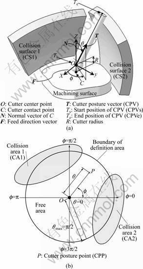
Fig.1 Concept of two-dimensinal C-space: (a) Definition of CPV in real space; (b) Definition of CPP in C-space
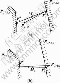
Fig.2 Collision avoidance method: (a) Case in free collision; (b) Case in collision detected
Step 1: Searching point vector,![]() on the boundary of CA1 in the minimum distance,
on the boundary of CA1 in the minimum distance, ![]()
Step 2: Searching point vector, ![]() on the boundary of CA2 in the minimum distance,
on the boundary of CA2 in the minimum distance, ![]()
Step 3: Mi is defined by ![]()
Step 4: PCPP,i converts with Mi.
Figure 3 shows the result of interference avoidance using the MC-space algorithm. After the MC-space algorithm is applied, the interfered tool, marked in dark gray in Fig.3(a), is avoided, as shown in Fig.3(b), and there are safe cutter posture vectors between blades. However, the changes of cutter posture vector are not continuous and show unnecessarily rapid changes. This discontinuity is expected to reduce the quality of the machined surface. Therefore, it is necessary to create a safe and smooth tool path with continuity, so that the cutter posture vector has only the minimum necessary changes.
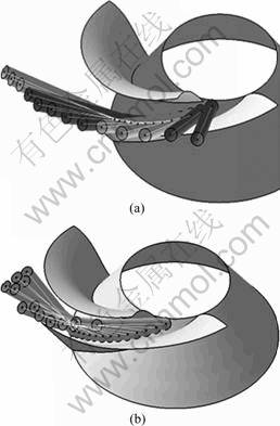
Fig.3 Collision free cutter posture by MC-space algorithm: (a) Collision detected; (b) Collision avoided
3 Continuity control method of cutter posture vectors
After the MC-space algorithm is applied, interference is avoided but cutter posture rapidly and discontinuously change, which is expected to affect the quality of the machined surface. This work tries to improve the quality of the machined surface and reduce the machining time at the same time by minimizing the cutter posture changes and forcing the continuous changes shown in Fig.4(b). Figure 4(a) is drawn after cutter figure is deleted in Fig.3(b) and represented as CPV, and a path connecting CPVe points, which are the end points of CPV, is represented as a thick line. As Fig.4(a) suggests, the curved path connecting the end points of the cutter posture vectors is not smooth due to the rapid cutter posture changes. Therefore, in order to avoid interference and allow cutter posture changes to be continuous, the curved path of the end points of the cutter posture vectors needs to be modified smoothly, as Fig.4(b) suggests.
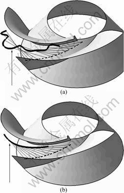
Fig.4 Schematic of ideal continuity control of CPVe: (a) Without continuity control of CPVe; (b) With continuity control of CPVe
In order to smoothly modify the curved path of the end points of the cutter posture vectors, this work uses modified B-spline (MB-spline) algorithm. The B-spline curve is an interpolation curve that passes through all the given points and has excessive curvature changes, as indicated by the dotted line in Fig.5(a), because it passes through each point ![]() on the CPVe path. However, the curve that this work purposes to obtain is a smooth approximation curve that passes between
on the CPVe path. However, the curve that this work purposes to obtain is a smooth approximation curve that passes between ![]() as shown by the thick line in Fig.5(a). Therefore, in order to create a favorable curve compared to the existing B-spline approximation curve while considering
as shown by the thick line in Fig.5(a). Therefore, in order to create a favorable curve compared to the existing B-spline approximation curve while considering ![]() points as control points, the boundary condition of the control points is modified and the MB-spline model was used. The result is shown in Eq.(1).
points as control points, the boundary condition of the control points is modified and the MB-spline model was used. The result is shown in Eq.(1). ![]() points, which are new CPVe points, can be obtained on a modified approximation curve path by dividing the same number as the CPVs points on the new curve created with the MB-spline algorithm. As a result, the new cutter posture vector
points, which are new CPVe points, can be obtained on a modified approximation curve path by dividing the same number as the CPVs points on the new curve created with the MB-spline algorithm. As a result, the new cutter posture vector ![]() connecting
connecting ![]() and
and ![]() points can be obtained, as shown by Eq.(2), which is given in Fig.5(b):
points can be obtained, as shown by Eq.(2), which is given in Fig.5(b):
![]() with 0��u��1 (1)
with 0��u��1 (1)
where

![]()
![]() (2)
(2)
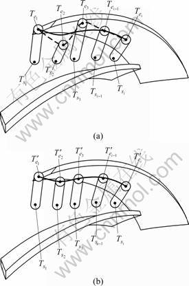
Fig.5 Schematic of fairing method: (a) Without continuity controlled CPV vectors; (b) With continuity controlled CPV vectors
The modeling and the measurement area of the impeller required for the verification experiment to apply the suggested method are shown in Fig.6. The model has a diameter of 162 mm, a length of 86 mm, and great curvature changes of blades to allow for obvious comparison; the measurement area is divided into three sections from the d3 area to the d9 area, where d3 area means area at the distance about 3 mm from the fillet between compression blade and hub. The reason for this division is that the curvature changes of the compression blades are most severe and cutter posture changes are expected to be most severe when interference occurs. So, the closer it is to compression blades, the greater the effect of the continuity control of the cutter posture with the suggested method is expected to be.
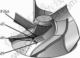
Fig.6 Modeling and measuring area of impeller
CATIA API and Visual Basic programs were used and applied with the suggested method for interference avoidance and continuity control. As a result, the cutter posture vector shown in Fig.7 is obtained. The cutter posture vector derived without continuity control method shows a severe change, as indicated in Fig.7(a), but the cutter posture vector with the suggested method shows minimum changes. In order to quantify the changes of cutter posture, the curvature of the path curve of the end points of the cutter posture vectors was analyzed. When the continuity control is not performed, the curvature is not continuous. However, when continuity control is performed, the curve is continuously connected. In Table 1, which compares quantitative curvature numbers, when continuity control is not performed, the maximum curvature is 2.095 mm-1. When continuity control is performed, the maximum curvature is 0.109 mm-1, which suggests that when continuity control is performed, the maximum curvature is very small, which means that the radius of curve is very great and continuous. Also the analysis of curvatures in each measurement area shows that the curvature change of the path curve connecting the end points of the cutter posture vectors is very great in d3 area which is close to the compression blades compared to the d9 area which is close to the suction blades as shown in Fig.8. This means that the closer it is to interference surface with severe curvature, the greater the effect of continuity control will be.
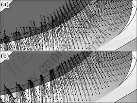
Fig.7 Comparison of CPV between two methods: (a) Without continuous method; (b) With continuous method
Table 1 Comparison of curvature analysis data between two methods
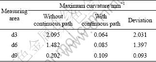
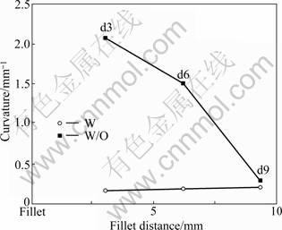
Fig.8 Comparison of curvature between two methods
4 Verification experiment
For the five-axis cutting experiment, cutting conditions and parameters of tool shape to verify the effectiveness of the continuity control are listed in Tables 2 and 3. The tool used in the machining was a tapered ball end mill with shank radius of 5 mm and mill radius of 3 mm. Each of the five blades had a 10% feedrate difference, in order to compare the effect of feedrate on machined surface. Figure 9 was taken when cutting experiment was performed in a M2 five-axis machine. It is high speed five-axis controlled milling machine, manufactured by Hwacheon in Korea, has configuration of table rotation and table tilting (TT-TR-AC) and is applied to manufacturing parts of small size with high accuracy. It is possible that a high speed milling with maximum 20 000 r/min and simultaneous five-axis control.
Table 2 Cutting conditions
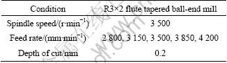
Table 3 Parameters of tool shape
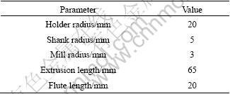
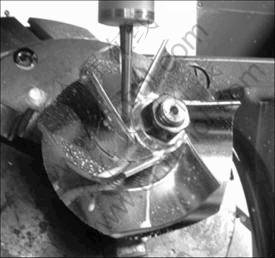
Fig.9 Cutting experiment in five-axis machine tool
The machining result was compared between without continuous and with continuous methods in aspects of surface shape, surface roughness, and machining time. Figure 10(b) shows the results for with continuous method; the surface shape is greatly improved compared to that shown in Fig.10(a), which shows the results of the without continuous method. This is due to the continuity of the cutter posture vector path and the stability of the cutting speed changes following the minimization of the cutter posture changes.
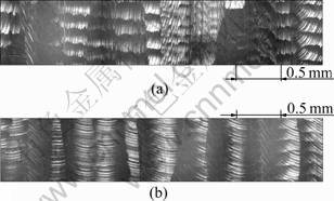
Fig.10 Comparison of shapes of machined surfaces: (a) Without continuous method; (b) With continuous method
The surface roughness was also compared and the surface roughness of the devised method is generally favorable as shown in Fig.11. Also, the average error of surface roughness in the d3 area is 0.09 ��m, which is greater than the 0.03 ��m in the d9 area. This means that the effect of continuity control is greater on surfaces closer to compression blades with high curvature changes.
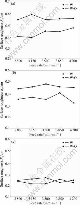
Fig.11 Comparison of surfaces roughness between two models (W/O��Without continuous model; W��With continuous model: (a) d3 area; (b) d6 and d3 area; (c) d9 area
The effect of feederate on surface roughness is not stable because the diameter of the impeller is small and constant speed section after acceleration is not long enough to influence the surface roughness.
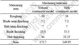
Table 4 lists the five-axis machining times in a model without continuous method and a model with the suggested method. The hub finishing time is 44 min in a model without continuous method due to the noncontinuity of the cutter posture vector and the frequent rotational feed control. However, it is 21.25 min, which is about 50% reduced in a continuous model due to the continuity of the cutter posture vector and the smooth rotational feed control, which increases the length of the constant speed section.
Table 4 Comparison of curvature analysis data between two methods
The results above verify that the efficiency of five-axis machining of impellers is improved in aspects of surface shape, surface roughness and machining time through continuity control of the cutter posture change.
5 Conclusions
1) five-axis cutting experiment to verify the effectiveness of the continuity control was performed. The results shows that the surface shape with continuous method is greatly improved and that this improvement is expected to contribute to the performance improvement of turbo machines by pursuing fluid flow inside the impeller.
2) After the suggested method is applied, the surface roughness is generally favorable; the closer it is to the compression blades with severe curvature changes, the greater the effect of improvement of surface roughness by continuity control is. Also, The hub finishing time is 21.25 min in a model with continuous method, and it is reduced by about 50% through continuity control of cutter posture changes due to the smooth rotational feed control and longer constant speed section. Consequently, the effectiveness of the suggested method is verified by identifying the improvement of efficiency of five-axis machining of an impeller in aspects of surface quality and machining time.
References
[1] CHOI B K, PARK J W, JUN C S. Cutter location data optimization in 5-axis surface machining [J]. Computer Aided Design, 1993, 25(6): 377-386.
[2] LAUWERS B, DEJINGHE P, KRUTH J P. Optimal and collision free tool posture in five-axis machining through the tight integration of tool path generation and machine simulation [J]. Computer Aided Design, 2003, 35: 421-432.
[3] LEE Y S. Non-isoparametric tool path planning by machining strip evaluation for 5-axis scultured surface machining [J]. Computer Aided Design, 1998, 30(7): 559-570.
[4] LIM P, YANG G E. Optimization of finish cutting condition of impeller with five-axis machine by response surface method [J]. J of KSME, 2007, 31(9): 924-933.
[5] PARK M J, KIM K. Effects of the tool path in the geometric characteristics of milled surface [J]. J of KSPE, 1998, 15(6): 58-63.
[6] FONTAINE M, DEVILLEZ A, MOUFKI A, DUDZINSKI D. Modeling of cutting forces in ball-end milling with tool-surface inclination: Part ��. Influence of cutting conditions, run-out, ploughing and inclination angle [J]. J of MPT, 2007, 189: 85-96.
[7] Gerald Farin. Curves and Surfaces for CAGD [M]. Academic Press, 2002: 119.
[8] CHOI B K, KIM D H, JERARD R B. C-space approach to tool-path generation for die and mould machining [J]. Computer Aided Design, 1997, 29(9): 657-669.
[9] MORISHIGE K, KASE K, TAKEUCHI Y. Collision free tool path generation using 2-dimensional c-space for 5-axis control machining [J]. The International Journal of Advanced Manufacturing Technology, 1997, 13(6): 393-400.
[10] JUN C S, CHA K, LEE Y S. Optimizing tool orientations for 5-axis machining by configuration-space search method [J]. Computer Aided Design, 2003, 35: 549-566.
[11] MORISHIGE K, WAKAYAMA H. Optimum toll path generation for 5-axis control machining considering tool attitude change [J]. The International Journal of Advanced Manufacturing Technology, 2005, 71(5): 639-643.
[12] HWANG J D, JUNG Y G. A Study on the efficiency improvement of reverse engineering and 5-axis control machining using MC-space algorithm [J]. Journal of Korean Society of Precision Engineering, Fall Conference, 2006: 103-104. (in Korean)
[13] HWANG J D, JUNG Y G. Modeling of a functional surface using a modified B-spline [J]. International Journal of Precision Engineering and Manufacturing, 2005, 6(1): 15-22.
[14] Ibrahim Zaid. CAD/CAM theory and practice [M]. Ohio: McGraw-Hill, 1995: 242.
[15] JEAN M L, EMMANUEL D, CLAIRE L, PIERRE B. A new format for 5-axis tool path computation, using B-spline [J]. Computer Aided Deign, 2004, 26: 1219-1229.
(Edited by DENG L��-xiang)
Foundation item: Work supported by the Second Stage of Brain Korea 21 Projects; Project(RTI04-01-03) supported by the Regional Technology Innovation Program of the Ministry of Knowledge Economy (MKE) of Korea
Received date: 2011-04-26; Accepted date: 2011-10-10
Corresponding author: JUNG Yoon-gyo, Professor, PhD; Tel: +82-55-213-3604; E-mail: ygjung@changwon.ac.kr
Abstract: During five-axis machining of impeller, the excessive local interference avoidance leads to inconsistency of cutter posture, low quality of machined surface and increase of processing time. Therefore, in order to improve the efficiency of five-axis machining of impellers, it is necessary to minimize the cutter posture changes and create a continuous tool path while avoiding interference. By using an MC-space algorithm for interference avoidance, an MB-spline algorithm for continuous control was intended to create a five-axis machining tool path with excellent surface quality and economic feasibility. A five-axis cutting experiment was performed to verify the effectiveness of the continuity control. The result shows that the surface shape with continuous method is greatly improved, and the surface roughness is generally favorable. Consequently, the effectiveness of the suggested method is verified by identifying the improvement of efficiency of five-axis machining of an impeller in aspects of surface quality and machining time.
