
Trans. Nonferrous Met. Soc. China 24(2014) s14-s19
Effect of stress ratio on fatigue lifetime and crack growth behavior of WC-Co cemented carbide
Hiroko MIKADO1, 2, Sotomi ISHIHARA3, Noriyasu OGUMA1, Kenichi MASUDA1, Syo KITAGAWA1, Shingo KAWAMURA2
1. Department of Mechanical Engineering, University of Toyama, Toyama 938-8601, Japan;
2. Machinery and Engineering Group, YKK Corporation, Toyama 930-8555, Japan;
3. National Institute of Technology, Toyama College, Toyama 939-8630, Japan
Received 18 June 2013; accepted 7 January 2014
Abstract:
Two types of fatigue tests, a rotating bending fatigue test and a three- or four-point bending fatigue test, were carried out on a fine grained WC-Co cemented carbide to evaluate its fatigue crack growth behavior and fatigue lifetime. From successive observations of the specimen surface during the fatigue process, it was revealed that most of the fatigue lifetime of the tested WC-Co cemented carbide was occupied with crack growth cycles. Using the basic equation of fracture mechanics, the relationship between the fatigue crack growth rate (da/dN) and the maximum stress intensity factor (Kmax) was derived. From this relation, both the values of the threshold intensity factor (Kth) and the fatigue fracture toughness (Kfc) of the material were determined. The fatigue lifetime of the WC-Co cemented carbide was estimated by analysis based on the modified linear elastic fracture mechanics approach. Good agreement between the estimated and experimental fatigue lifetimes was confirmed.
Key words:
WC-Co cemented carbides; fatigue lifetime; crack growth rate; stress intensity factor;
1 Introduction
WC-Co cemented carbides have been widely used for cutting tools, die tools, and machine parts because they have excellent wear resistance superior to that of tool steels. To use them effectively without fracture failure, it is important to understand their fatigue crack growth behavior and fatigue lifetime.
FUJIWARA et al [1] clarified the fatigue fracture properties of hot-isostatic sintered WC-Co cemented carbides by comparing with those of conventionally sintered cemented carbides. OTSUKA et al [2] studied the effect of the stress ratio on the fatigue lifetime of cemented carbides. SAKAGAMI et al [3] clarified the effects of the WC grain size and Co content on the fatigue characteristics of cemented carbides. SCHLEINKOFER et al [4] investigated the fatigue behavior of hard metals and cermets under cyclic mechanical loading. Although many studies on the fatigue lifetime of WC-Co cemented carbides have already been reported as indicated above, the number of papers that describe the quantitative analysis of the fatigue behavior of these materials is limited. Thus, more detailed studies are required to predict their fatigue lifetime and clarify their fatigue mechanism.
A few investigations have focused on the fatigue crack growth behavior of WC-Co cemented carbides. TORRES et al [5,6] studied the effects of the WC grain size and Co content on the fatigue crack growth behavior. They found a relationship between the fatigue limit and the threshold level for the fatigue crack growth (Kth). They also pointed out that the cyclic crack growth behavior is significantly determined by the maximum stress intensity factor (Kmax). ISHIHARA et al [7] carried out the fatigue tests using the WC-Co cemented carbide to investigate the effect of the stress ratio on its short fatigue crack growth behavior. They [8] also performed the repeated thermal shock tests on this material to study the thermomechanical effects on its fatigue crack growth behavior. It was clarified that the rate of fatigue crack growth in the material was mainly determined by Kmax at high Kmax values , and that this feature was enhanced at high temperatures. HIROSE et al [9] performed the fatigue tests using WC-Co cemented carbides to investigate the effects of the stress ratio and Co content on their fatigue crack growth behavior. They found a clear effect of the stress ratio on the fatigue crack growth behavior of these materials. It was concluded that the Co binder-phase transformation induced by cyclic fatigue loading significantly affects the fatigue crack growth behavior. Despite the summary of the reviews given above, the effect of the stress ratio on the fatigue lifetime of WC-Co cemented carbides is still unknown. Thus, further studies are required to resolve the above issue.
In this work, two types of fatigue tests were carried out on the fine-grained WC-Co cemented carbides to evaluate its fatigue crack growth behavior and fatigue lifetime. Furthermore, from the obtained results, its crack growth behavior was analyzed on the basis of the modified linear elastic fracture mechanics approach. The analysis method used in this work was developed by MCEVILY et al [10,11], who showed the effectiveness of the method for the evaluation of fatigue lifetime of ductile materials, such as aluminum alloy [10] and magnesium alloy [12], and also high-strength materials, such as high-speed steel [13]. In the present study, the modified linear elastic fracture mechanics approach was employed to estimate the fatigue lifetime of the WC-Co cemented carbides.
2 Experimental
2.1 Material and test specimens
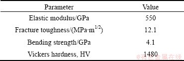
In this work, a commercially available fine-grained WC-Co cemented carbide was used as the test specimen. Tables 1 and 2 show the chemical composition and mechanical properties of the WC-Co cemented carbide, respectively. Its microstructure is shown in Fig. 1. The average diameter of WC grain is approximately 0.8 ��m.
Table 1 Chemical composition of test specimen (mass fraction, %)
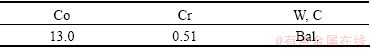
Table 2 Mechanical properties of test specimen
2.2 Experimental procedure
2.2.1 Fatigue test
To evaluate the fatigue lifetimes, some types of fatigue tests, a rotating bending fatigue test at a stress ratio of -1 (R=-1), a four-point bending fatigue test at R=0.1, 0.2, and a three-point bending fatigue test at R= 0.5 were conducted at 10 Hz in laboratory air at room temperature. For all fatigue tests, the hourglass-shaped specimen with a minimum diameter of 3 mm shown in Fig. 2(a) was used. The specimen surface was ground to a surface roughness (Ra) of 0.1 ��m or less.
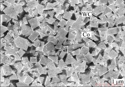
Fig. 1 Microstructure of WC-Co cemented carbide showing average WC grain diameter approximately of 0.8 ��m
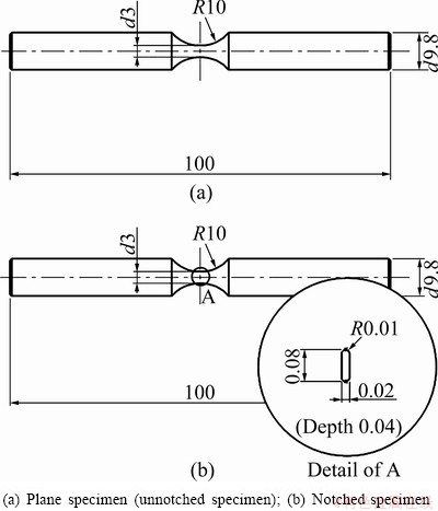
Fig. 2 Dimensions of test specimens used for fatigue test (Unit: mm)
2.2.2 Short surface crack growth test
To evaluate the crack growth rate of a short surface crack, a rotating bending fatigue test was conducted under the same conditions as above. A notched specimen was used to determine the fatigue crack growth behavior. Figure 2(b) shows the notched specimen. For the notched specimen, the artificial notch with a length of 80 ��m, a width of 20 ��m, and a depth of 40 ��m was introduced into the specimen by laser beam machining.
The fatigue test was interrupted at constant intervals to obtain a replica of the specimen surface. The crack length recorded on the replica was determined using an optical microscope. To calculate the maximum stress intensity factor (Kmax), the following expression was used:
 (1)
(1)
where ��a is the stress amplitude; a is the half crack length; and Y is a crack-shape correction factor. A value of 0.73 was used for Y assuming that the crack shape is semi-circular [14].
2.2.3 Long through crack growth test
In addition to the crack growth behavior of a short surface crack, the crack growth behavior of a long through-thickness crack was evaluated using the compact tension specimen shown in Fig. 3. The crack length was measured using the replication technique as mentioned above. To calculate the stress intensity factor (K), the following expression was used [15]:
 (2)
(2)
 (3)
(3)
and

 (4)
(4)
where P is the applied load; t is the specimen thickness; W is the specimen width; and  is the crack length.
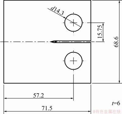
Fig. 3 Dimensions of test specimen used for CT test (Unit: mm)
The crack opening stress intensity factor (Kop) during a loading cycle was determined with the unloading elastic compliance method [16] by affixing strain gauges ahead of the crack tip.
3 Results
3.1 S-N curves
Figure 4 shows S-N curves of specimens at stress ratios of R=-1, 0.1, 0.2 and 0.5. The results in Fig. 4 were obtained from rotating bending fatigue tests at R=-1, from four-point bending fatigue tests at R=0.1 and 0.2, and from four-point bending fatigue tests at R=0.5. The vertical axes in Figs. 4(a) and (b) are the stress amplitude ��a and the maximum stress ��max, respectively. It can be seen from Fig. 4(a) that the fatigue limits are estimated to be 1.7 GPa (R=-1), 1.35 GPa (R=0.1), 1.25 GPa (R=0.2) and 0.9 GPa (R=0.5), respectively. Furthermore, from Fig. 4(a), it is evident that the stress amplitude (��a) at a constant fatigue lifetime increases with a decrease in the value of R. On the other hand, in Fig. 4(b), the maximum stress (��max) at a constant fatigue lifetime decreases with a decrease in the value of R.
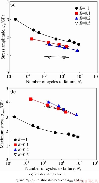
Fig. 4 S-N curves for test specimens
3.2 Crack growth behavior
Successive observations of the specimen surface during the fatigue process of the unnotched specimen were performed. It was found that the fatigue crack initiates early during the fatigue process. Thus, most of the fatigue process was found to be occupied with the crack growth period.
Figure 5 shows the relationship between the crack growth rate (da/dN) and the maximum stress intensity factor (Kmax) for both the short surface fatigue crack and the long through fatigue crack. The experimental data are approximated well by the dotted curve, which represents the basic equation of fracture mechanics (Eq. (5)). From the relationship, the threshold stress intensity factor (Kth) and the fatigue fracture toughness (Kfc) of the material are estimated to be 4.7 and 10 MPa��m1/2, respectively.
 (5)
(5)
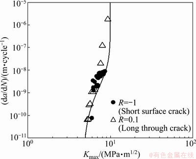
Fig. 5 Relationship between da/dN and Kmax
4 Discussion
4.1 Derivation of S-N curves using parameter M
MCEVILY et al [10,11] proposed a method of analyzing the crack growth behavior based on the modified linear elastic fracture mechanics approach. This approach includes the consideration of elastic-plastic behavior, the development of the crack closure, and the relationship between the threshold for fatigue crack growth and the endurance limit. To derive the S-N curves for the test specimens, this analysis was also performed. In this approach, the crack growth rate (da/dN) is expressed as
 (6)
(6)

 (7)
(7)
 (8)
(8)
where re is the effective length dimension; �� is the length of the newly formed crack; Kopmax is the maximum crack opening stress intensity factor; Keffth is the threshold of the effective stress intensity factor range, and ��y is the bending strength in substitution for the yield strength. The first term on the right side of Eq. (7) reflects the elastic-plastic behavior near the crack tip as well as the relationship between the threshold for fatigue crack growth and the endurance limit. The second term on the right side of Eq. (7) defines the development of crack closure. The last term on the right side of Eq. (7) is the threshold of the effective stress intensity factor range, below which the crack cannot propagate.
Figure 6 shows a log-log plot of the relationship between the crack growth rate (da/dN) and the modified linear elastic fracture mechanics parameter (M). The values of the parameters used for the calculation of M are listed in Table 3. In Fig. 6, the data for the short surface fatigue crack obtained from the rotating bending fatigue tests performed at R=-1 are plotted. In accord with Eq. (9), the slope was set at 2. As can be seen from the figure, the relationship between da/dN and M for the cemented carbide can be expressed as
 (9)
(9)
It is possible to regard the crack propagation lifetime (Np) as being equal to the total fatigue lifetime (Nf) because the initial fatigue crack was observed in the early stage of the fatigue process. The crack propagation lifetime can be estimated by numerically integrating Eq. (9) from the initial crack length of 2re [10] to the final crack length, which can be determined from the fatigue fracture toughness (Kfc) using Eq. (1). Figure 7 shows a comparison between the experimental data and calculated results. As can be seen from the figure, the calculated S-N curves are in good agreement with the experimental data for both R values.
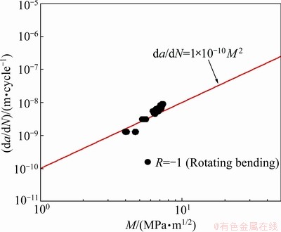
Fig. 6 Relationship between da/dN and M
Table 3 Parameters used for calculation of M
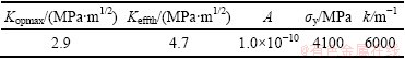
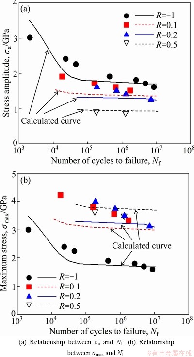
Fig. 7 Comparison between experimental data and calculated results
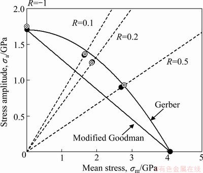
Fig. 8 Relationship between stress amplitude (��a) and mean stress (��m)
4.2 Estimation of relationship between ��a and ��m
Figure 8 shows the relationship between the stress amplitude (��a) and the mean stress (��m), where the fatigue lifetime, i.e., 1��107 cycles, is taken as a parameter. In the figure, the experimental data and the results predicted using the relationship between da/dN and M are shown for the comparison. In addition, the Gerber diagram and the modified Goodman diagram are also shown in the figure. It can be seen that the predictions based on parameter M are in good agreement with the experimental data. Furthermore, the relationship between the stress amplitude (��a) and the mean stress (��m) closely fits the Gerber diagram [17] (Eq. (10)) rather than the modified Goodman diagram [17] (Eq. (11)).
 (10)
(10)
 (11)
(11)
In Eqs. (10) and (11), ��w is the fatigue limit for R=-1, and ��B is the bending strength in substitution for the tensile strength.
5 Conclusions
1) S-N curves were obtained at different stress ratios (R). The stress amplitude (��a) at a constant fatigue lifetime increases with a decrease in the value of R. However, the reverse is true for the relationship between the maximum stress (��max) and the number of cycles to failure (Nf).
2) Most of the fatigue process was found to be occupied with the crack growth period. The relationship between (da/dN) and (Kmax) expressed by Eq. (5) was obtained for the present material. The threshold stress intensity factor (Kth) and the fatigue fracture toughness (Kfc) of the material were evaluated to be 4.7 and 10 MPa��m1/2, respectively.
3) The calculated S-N curves at different R values of using the modified linear elastic fracture mechanics approach are in good agreement with the experimental curves.
4) The predicted relationship between the stress amplitude (��a) and the mean stress (��m) based on parameter M is in good agreement with the experimental data. Furthermore, the relationship between ��a and ��m expressed by the Gerber diagram closely matches the experimental relationship obtained for the cemented carbide.
Acknowledgement
The authors express their thanks to Daisuke SATO and Yuki TOCHIKAWA, students of University of Toyama, for their help in performing the fatigue tests.
References
[1] FUJIWARA Y, UEDA H, MASATOMI H, SUZUKI H. Fatigue of hot isostatic pressed WC-12%Co alloys [J]. Journal of the Japan Society of Powder and Powder Metallurgy, 1980, 27(6): 181-184.
[2] OTSUKA A, TOHGO K, SUGAWARA H, UEDA F. Tension- compression fatigue of WC-12%Co hardmetal [J]. Journal of the Society of Materials Science, 1987, 36(1): 135-140.
[3] SAKAGAMI K, KOUNO S, YAMAMOTO T. Bending fatigue characteristics of cemented carbides for cold forging tools [J]. Journal of the Japan Society of Powder and Powder Metallurgy, 2006, 54(4): 260-263.
[4] SCHLEINKOFER U, SOCKEL H G, SCHLUND P,  K, HEINRICH W. Behaviour of hard metals and cermets under cyclic mechanical loads [J]. Materials Science and Engineering A, 1995, 194: 1-8.
[5] LLANES L, TORRES Y, ANGLADA M. On the fatigue crack growth behavior of WC-Co cemented carbides: Kinetics description, microstructural effects and fatigue sensitivity [J]. Acta Materialia, 2002, 50(9): 2381-2393.
[6] TORRES Y, ANGLADA M, LLANES L. Fatigue mechanics of WC-Co cemented carbides [J]. International Journal of Refractory Metals and Hard Materials, 2001, 19(4-6): 341-348.
[7] ISHIHARA S, GOSHIMA T, ADACHI K, YOSHIMOTO T. Effect of stress ratio on the short fatigue crack growth behavior in cemented carbides [J]. Transactions of the Japan Society of Mechanical Engineers A, 1998, 64: 2145-2151.
[8] ISHIHARA S, GOSHIMA T, NOMURA K, YOSHIMOTO T. Crack propagation behavior of cermets and cemented carbides under repeated thermal shocks by the improved quench test [J]. Journal of Materials Science, 1999, 34(3): 629-636.
[9] HIROSE Y, BOO M, MATSUOKA H, PARK Y. Influence of stress ratio and WC grain size on fatigue crack growth characteristics of WC-Co cemented carbides [J]. Journal of the Society of Materials Science, 1997, 46(12): 1402-1408.
[10] ISHIHARA S, MCEVILY A J. Analysis of short fatigue crack growth in cast aluminum alloys [J]. International Journal of Fatigue, 2002, 24(11): 1169-1174.
[11] ENDO M, MCEVILY A J. Prediction of the behavior of small fatigue cracks [J]. Materials Science and Engineering A, 2007, 468: 51-58.
[12] ISHIHARA S, MCEVILY A J, SATO M, TANIGUCHI K, GOSHIMA T. The effect of load ratio on fatigue life and crack propagation behavior of an extruded magnesium alloy [J]. International Journal of Fatigue, 2009, 31(11-12): 1788-1794.
[13] ISHIHARA S, YOSHIFUJI S. MCEVILY A J, KAWAMOTO M, SAWAI M, TAKATA M. Study of the fatigue lifetimes and crack propagation behaviour of a high speed steel as a function of the R value [J]. Fatigue & Fracture of Engineering Materials & Structures, 2010, 33(5): 294-302.
[14] MURAKAMI Y, ISHIDA M. Analysis of stress intensity factors for surface crack of arbitrary shape and stress field at vicinity of surface [J]. Transactions of the Japan Society of Mechanical Engineers A, 1987, 51: 1050-1056.
[15] MURAKAMI Y. Stress intensity factors handbook [M]. Oxford: Pergamon Press, 1987.
[16] KIKUKAWA M, JONO M, TANAKA K, TAKATANI M. Measurement of fatigue crack propagation and crack closure at low stress intensity level by unloading elastic compliance method [J]. Journal of the Society of Materials Science, Japan, 1976, 25(276): 899-903.
[17] MCEVILY A J, ISHIHARA S, RIE K T, PORTELLA P D. An analysis of the Gerber parabolic relationship based on small fatigue crack growth behavior [C]//Proceedings of International Conference on Low Cycle Fatigue Elastic-Plastic Behavior of Materials. London: Elsevier, 1998: 505.
Ӧ���ȶ�WC-CoӲ�ʺϽ�ƣ������������������Ϊ��Ӱ��
Hiroko MIKADO1, 2, Sotomi ISHIHARA3, Noriyasu OGUMA1, Kenichi MASUDA1, Syo KITAGAWA1, Shingo KAWAMURA2
1. Department of Mechanical Engineering, University of Toyama, Toyama 938-8601, Japan;
2. Machinery and Engineering Group, YKK Corporation, Toyama 930-8555, Japan;
3. National Institute of Technology, Toyama College, Toyama 939-8630, Japan
ժ Ҫ��ͨ������ƣ�����飺��ת����ƣ�������3-��4-������ƣ���������ϸ��WC-CoӲ�ʺϽ������������Ϊ��ƣ��������ƣ�������������������ԵĴ�WC-CoӲ�ʺϽ��ƣ������ȡ���������������ڡ����ö�����ѧ���������Ƶ���ƣ��������������(da/dN)�����Ӧ��ǿ������(Kmax)�Ĺ�ϵ�����ݴ˹�ϵ����ò��ϵ�ǿ��������ֵ(Kth)��ƣ�Ͷ�������ֵ(Kfc)���������������Ե��Զ�����ѧ���̣���WC-CoӲ�ʺϽ���ϵ�ƣ���������м��㣬ƣ�������ļ�������ʵ�����ǺϽϺá�
�ؼ��ʣ�WC-CoӲ�ʺϽ�ƣ�������������������ʣ�Ӧ��ǿ������
(Edited by Wei-ping CHEN)
Corresponding author: Sotomi ISHIHARA; Tel: +81-76-493-5402; Fax: +81-76-492-3859; E-mail: ishi@nc-toyama.ac.jp
DOI: 10.1016/S1003-6326(14)63282-9
Abstract: Two types of fatigue tests, a rotating bending fatigue test and a three- or four-point bending fatigue test, were carried out on a fine grained WC-Co cemented carbide to evaluate its fatigue crack growth behavior and fatigue lifetime. From successive observations of the specimen surface during the fatigue process, it was revealed that most of the fatigue lifetime of the tested WC-Co cemented carbide was occupied with crack growth cycles. Using the basic equation of fracture mechanics, the relationship between the fatigue crack growth rate (da/dN) and the maximum stress intensity factor (Kmax) was derived. From this relation, both the values of the threshold intensity factor (Kth) and the fatigue fracture toughness (Kfc) of the material were determined. The fatigue lifetime of the WC-Co cemented carbide was estimated by analysis based on the modified linear elastic fracture mechanics approach. Good agreement between the estimated and experimental fatigue lifetimes was confirmed.
