
Trans. Nonferrous Met. Soc. China 25(2015) 80-87
Bonding interface characteristic and shear strength of diffusion bonded Ti-17 titanium alloy
Hong LI, Chao ZHANG, Hong-bin LIU, Miao-quan LI
School of Materials Science and Engineering, Northwestern Polytechnical University, Xi��an 710072, China
Received 25 February 2014; accepted 16 August 2014
Abstract:
The bonding interface characteristic and shear strength of diffusion bonded Ti-17 titanium alloy at different bonding time were investigated. The results show that the average size of voids decreases while the amount of voids decreases after increasing to the maximum value with the increasing bonding time. The irregular void with a scraggly edge tends to an ellipse void with smooth surface and then changes to a tiny void with round shape. The grains across bonding interface occur at bonding time of 60 min. The shear strength of bond increases with increasing bonding time, and the highest shear strength of bond is 887.4 MPa at 60 min. The contribution of plastic deformation on the void closure and the increase of shear strength is significant even though the action time of plastic deformation is short.
Key words:
Ti-17 titanium alloy; diffusion bonding; bonding interface; void; shear strength;
1 Introduction
Ti-17 titanium alloy is widely used to manufacture the aircraft components, i.e. compressor discs and fan blades owing to high strength, superior fracture toughness and high hardenability [1,2]. This alloy can be bonded by fusion welding and friction welding, including TIG welding, electron beam welding in vacuum, linear friction welding and so on [3-5], but there are unhomogeneous microstructure and residual stress in the joints which induce the dissatisfactory mechanical properties.
Diffusion bonding (DB) is an attractive joining technique for many advanced materials and has been widely used in aviation, aerospace, instrumentation and electronics industries [6,7]. There are no fusion zone, heat affected zone, residual stress and macroscopic deformation in bond [8,9], which is different from fusion welding and friction welding. The microstructure and properties of bond match with those of the base metal. DB is considered as one of the most suitable joining methods for titanium alloys.
In the DB process, some physical and chemical processes occur simultaneously at the bonding interface. The void closure is one of the crucial processes to affect the characteristic of bonding interface and determine the mechanical properties of DB bond.  SALAZAR et al [10] considered DB as a process in which initial interfacial voids between the two contact surfaces tend to collapse. Many researchers proposed some models for void closure so as to optimize bonding parameters [11-14]. In the experimental investigation, the characteristic of bonding interface and mechanical properties varied with bonding parameters were investigated in the DB process of titanium alloy [15], magnesium alloy [16], steel [17], TiAl intermetallic alloy [18] and so on. However, the simple and qualitative investigation cannot exactly reveal the void evolution at the bonding interface. In this work, the variation of morphology, size, amount and distribution of voids in depth was conduced, the bonding interface characteristic of diffusion bonded Ti-17 titanium alloy was observed by SEM and the mechanical properties of bond were evaluated by the shear test. The variation of size, amount and distribution of voids at the bonding interface with bonding time was studied and analyzed quantitatively to reveal the DB mechanisms.
2 Experimental
The material for DB is a Ti-17 titanium alloy, of which the chemical composition is as follows: 5.1% Al, 2.3% Sn, 2.0% Zr, 4.1% Mo, 4.1% Cr, 0.04% Fe, 0.01% C, 0.02% N, 0.004% H, 0.11% O and balance Ti. The original microstructure of Ti-17 titanium alloy can be seen in Fig. 1(a), in which some equiaxed primary �� grains and a few elongated primary �� grains along the direction of the compressive axis distribute in the �� matrix. The grain size of primary �� phase of the base Ti-17 titanium alloy is (2.7��0.6) ��m. The specimens of Ti-17 titanium alloy for DB are cylinders with diameter of 30.0 mm and height of 20.0 mm. The shear strength of the base Ti-17 titanium alloy is 871.8 MPa. The SEM image in Fig. 1(b) shows that a mass of dimples distribute on the fracture surface and the failure model is a typical ductile fracture.
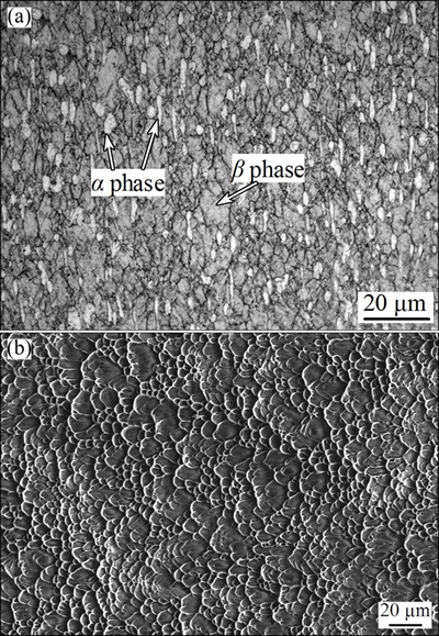
Fig. 1 Original microstructure (a) and SEM image of shear fracture surface (b) of base Ti-17 titanium alloy (The direction of shear is horizontal)
Prior to DB, the bonding surfaces of Ti-17 titanium alloy specimens were ground by 600#, 1000# and 1500# grit SiC papers sequentially. The ground surfaces were ultrasonically cleaned in ethanol for 10 min and then dried. The cleaned specimens were assembled together and then placed in a typed ZYD-60L vacuum furnace. The schematic of DB assemble is illustrated in Fig. 2. As the vacuum degree in the furnace reached 5.0��10-3 Pa, the DB specimens were heated to 860 ��C at a heating rate of 15 ��C/min and then held for 5 min. The bonding time at a bonding pressure of 3 MPa was chosen as 1, 3, 5, 10, 20, 30 and 60 min, respectively. After bonding, the specimens were cooled in furnace to room temperature.
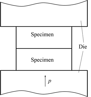
Fig. 2 Schematic of DB assemble
The cross sections of Ti-17 titanium alloy bonds were prepared by standard metallographical method. The characteristic of bonding interface was observed with a SUPRA-55 SEM microscope. The size of void was denoted by the maximum length of void in the direction of bonding interface. The size and amount of voids and grain size of primary �� phase were measured in thirty SEM images abutting the bonding interface by Image-Pro Plus software. The average size and amount of voids at the bonding interface length of 100 ��m were calculated.
The shear specimens of bonding interface were cut from the Ti-17 titanium alloy bonds as shown in Fig. 3(a). The dimensions of shear specimens are illustrated in Fig. 3(b), in which the arrows show the direction of shear force. The shear tests were conducted on an INSTRON 3382 universal machine with a crosshead speed of 1.0 mm/min. The fracture surfaces after shearing were observed with a SUPRA-55 SEM microscope.
3 Results and discussion
3.1 Bonding interface morphology
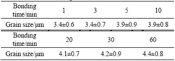
Figure 4 shows the SEM images of bonding interfaces in the Ti-17 titanium alloy bonds. As seen from Fig. 4(a), many long and broad voids distribute at the bonding interface. Only a few zones at the bonding interface contact completely. The edges of voids are wavy and scraggly. As the bonding time increases to 3 min, more ridges of bonding surfaces contact together, and the void size in the length decreases while that in the height hardly changes (see Fig. 4(b)). The edges of voids are similar to those shown in Fig. 4(a). At bonding time of 5 min, all of ridges on the bonding surface contact completely as shown in Fig. 4(c). The size of residual voids decreases significantly and the shape of voids tends to be ellipse with smooth edge. However, the bonding line in the contact zones is wide at a high magnification shown in Fig. 4(c), which demonstrates an incomplete contact in 3D space. The bonding line at bonding time of 10 min is thin and clear, as shown in Fig. 4(d). There are some small and round voids at the bonding interface and the large sized voids cannot be found. The structure characteristic at the bonding interface at bonding time of 30 min in Fig. 4(e) is similar to that in Fig. 4(d), in which the thin bonding line is visible and the change of the morphology and size of voids is slight. The bonding line at bonding time of 60 min is not straight and continuous because of the formation of grains across bonding interface (GABI) shown in Fig. 4(f). There are only very few and tiny voids at the bonding interface of diffusion bonded Ti-17 titanium alloy. In addition, the elongated primary �� grains along the compressive axis convert gradually to equiaxed grains with the increasing bonding time, as shown in Fig. 4, which is mainly attributed to the increase of macroscopic deformation in the DB process of Ti-17 titanium alloy. The grain size of primary �� phase of Ti-17 titanium alloy bonds at different bonding time was measured and listed in Table 1. It can be seen from Table 1 that there is no variation in the grain size of primary �� phase as the bonding time increases from 1 min to 3 min. However, the grain size of primary �� phase increases from (3.4��0.7) ��m to (4.4��0.8) ��m as the bonding time increases from 3 min to 60 min.
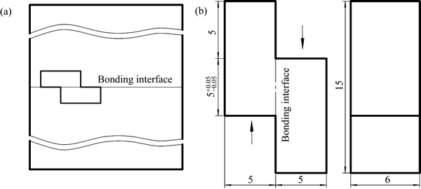
Fig. 3 Schematic of cutting location (a) and dimensions (b) of shear specimens (unit: mm)
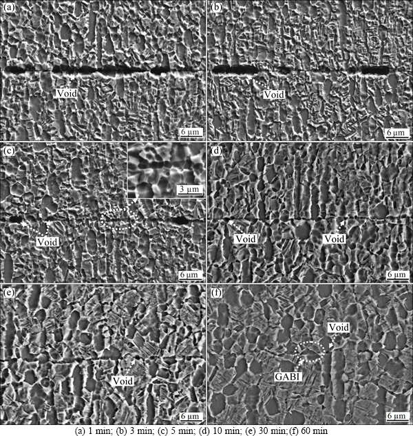
Fig. 4 SEM images of bonding interface bonded for different bonding time
Table 1 Grain size of primary �� phase of Ti-17 titanium alloy bonds at different bonding time
3.2 Void size and distribution
Figure 5 shows the distribution of void size at the bonding interface bonded for different bonding time. The distribution of void size at the bonding interface at bonding time of 1 min is dispersive. The size of the most voids is in the range of 3.8-18.3 ��m, and even the size of a few voids exceeds 49.0 ��m. The range of voids size at the bonding interface decreases with the increase of bonding time, in other words, the size of voids is homogeneous as the DB process of Ti-17 titanium alloy proceeds. The size of about 94.5% voids at bonding time of 10 min is in the range of 0.5-1.5 ��m, and that of about 92.6% voids at bonding time of 60 min is in the range of 0.2-1.1 ��m.
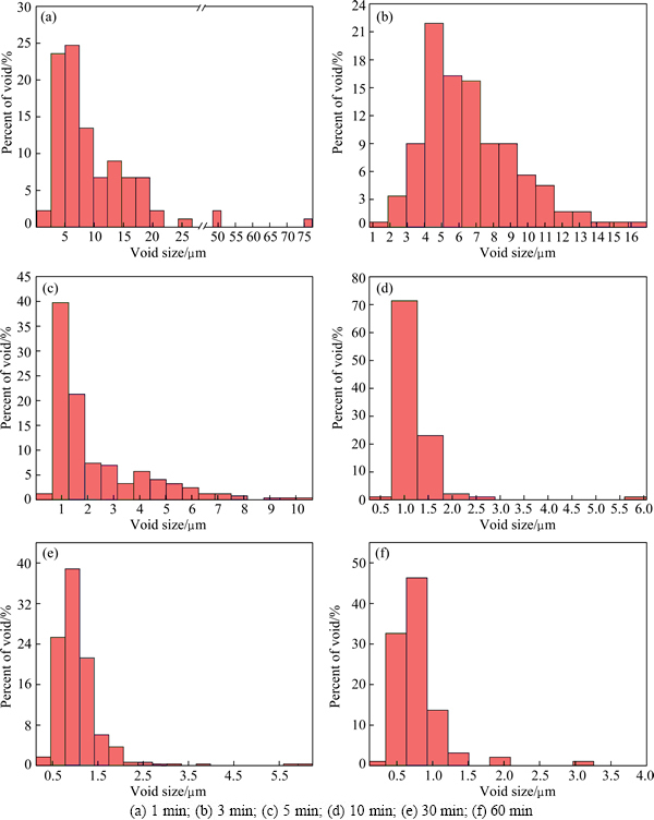
Fig. 5 Distribution of void size at bonding interface bonded for different bonding time
Figure 6 shows the variation of the average size and amount of voids with the bonding time at the bonding interface length of 100 ��m. At bonding time of 1 min, there are about eight voids with an average size of 9.4 ��m at the bonding interface length of 100 ��m. As the bonding time increases to 5 min, the average size of voids decreases rapidly to 2.0 ��m while the amount of voids at the bonding interface length of 100 ��m increases rapidly to about 14. Afterwards, the average size and amount of voids at the bonding interface length of 100 ��m decrease with the increasing bonding time. The average size of voids is about 1.0 ��m at bonding time of 10 min. At bonding time of 60 min, there are only about five voids with an average size of 0.7 ��m at the bonding interface length of 100 ��m. According to Fig. 6, the percent of bonded area of Ti-17 titanium alloy at different bonding time can be calculated and illustrated in Fig. 7. As shown in Fig. 7, the percent of bonded area increases evidently from 30.1% to 87.0% with the increasing bonding time from 1 min to 10 min while it increases slightly from 87.0% to 96.5% with the increasing bonding time from 3 min to 60 min.
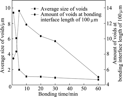
Fig. 6 Variation of average size and amount of voids at bonding interface length of 100 ��m
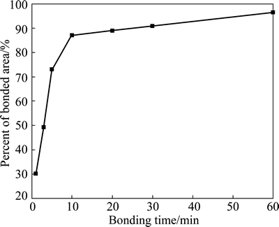
Fig. 7 Percent of bonded area of Ti-17 titanium alloy with bonding time
3.3 Bonding mechanisms
The DB process of metal and/or alloy is generally attributed to several mechanisms as follows [13,19]: 1) plastic deformation; 2) diffusion mechanism, including surface diffusion from surface sources to a neck, volume diffusion and grain boundary diffusion; 3) power-law creep. In these DB mechanisms, surface diffusion, volume diffusion and grain boundary diffusion will only influence the size and shape of voids, which leads to a decrease in amount of voids but an increase in amount of voids if the size of voids decreases to zero. The power-law creep usually acts on void closure after the plastic deformation completes, and the amount of voids with small size at the bonding interface does not increase. So, an increase in amount of voids at the bonding interface mainly results from the plastic deformation.
The ground surface of bond is scraggly and there are many ridges which can be seen from the oscillogram of the surface roughness, as shown in Fig. 8. At the beginning of DB of Ti-17 titanium alloy, a few ridges with different heights contact randomly and the voids with different sizes will be formed. If two ridges with the largest height contact together, a void with abnormally large size may be formed. Because of limited contact zones at the bonding interface, the imposed pressure of contact zones exceeds the resistance against plastic deformation of Ti-17 titanium alloy. The ridges on the surface of large sized void gradually contact together with the increasing bonding time because of the plastic deformation and the large sized void is divided into some smaller size voids. Therefore, the size of voids decreases but the amount of voids increases. Meanwhile, because the size of voids is larger than that of the primary �� grains, numerous grain boundary interfaces intersect the void surface, as shown in Figs. 4(a) and (b). The mass transfer path via the grain boundary will significantly influence the void closure [20], which will promote a decrease in size of voids.
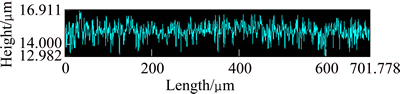
Fig. 8 Oscillogram of surface roughness for Ti-17 titanium alloy ground by1500# grit SiC paper
As the DB process proceeds, all ridges on the bonding surface contact together because of the plastic deformation so as to increase the contact area at the bonding interface. The scraggly edges of voids tend to be smooth and the amount of voids at the bonding interface reaches the maximum value. At this stage, the voids with abnormally large size disappear and the size of most voids tends to be homogenous. With an increase in bonding time, the contribution of plastic deformation on void closure disappears and then the surface diffusion, interface diffusion, grain boundary diffusion and power-law creep gradually dominate the void closure. Compared with plastic deformation, mass transfer processes in diffusion and power-law creep are very slow in which the void closure highly depends on the bonding time. In addition, the grain boundary interfaces encircling the void decreases with a decrease in size of voids, which reduces mass transfer paths via grain boundary, so the grain boundary diffusion becomes weak. In the DB process, the shape of voids tends to round shape and the surface curvature of voids tends to be equal with an increase in bonding time, as shown in Fig. 4. According to the dynamic condition of surface diffusion proposed by MA et al [21], the action of surface diffusion on void closure for round voids will be invalid. Therefore, the speed of void closure decreases with an increase in bonding time. As the void closure completes, the bonding surfaces contact completely and some grains across bonding interface generate, which is a guarantee for forming metallurgical bond with the microstructure comparable to that of the base alloy.
3.4 Shear strength of bond
Figure 9 shows the variation of shear strength of bond with the bonding time. The SEM images of fracture at the bonding interface at different bonding time are shown in Fig. 10. The shear strength of bond is about 352.7 MPa at bonding time of 1 min. The large number of un-contact zones can be observed on the fracture surface, as shown in Fig. 10(a), which is corresponding to the large sized voids shown in Fig. 4(a). There are only a few zones bonded together, in which islands of cusps are left after shearing. Most of the contact zones are not connected, which results in low shear strength and the failure model is a brittle fracture. The shear strength of bond at bonding time of 3 min quickly increases to a high level which is equal to that of the base Ti-17 titanium alloy, although there are many voids distributing at the bonding interface, as seen from Fig. 4(b). It can be attributed to the deformation strengthening in the bonded zones. About half of the fracture surface exhibits islands of cusps that are typical features of ductile fracture. However, there is still half of the fracture surface on which a feature of brittle fracture appears. In addition, there are about nine voids with an average size of 6.1 ��m at the bonding interface length of 100 ��m, as shown in Fig. 6. In situ observation of interfacial fatigue crack growth in diffusion bonded joints of austenitic stainless steel was implemented by LI et al [22], in which the coalescence of voids with crack will accelerate the fatigue crack growth so as to be not beneficial to fatigue strength. The Charpy impact test of diffusion bonded Ti-6Al-4V titanium alloy demonstrated that the low percent of boned area indicated low impact energy [10]. Therefore, the bond obtained at the bonding time of 3 min is not a metallurgical bond even if its shear strength reaches a higher value.
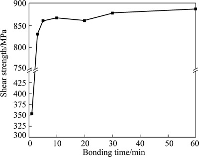
Fig. 9 Shear strength of bond of Ti-17 titanium alloy with bonding time
As the bonding time increases from 3 min to 10 min, the shear strength of bond increases slightly. But there is a little decrease in shear strength at bonding time of 20 min, which can be considered as the experimental error, because the difference between the shear strength at bonding time of 20 min and that at bonding time of 10 min is smaller than 10 MPa. The highest shear strength is 887.4 MPa at bonding time of 60 min in the present work. Figures 10(c) and (d) present that a lot of dimples distribute on the fracture surfaces and the tear cusps are in the shear direction. The results indicate that the failure model of bonding interface in the Ti-17 titanium alloy bond is a ductile fracture as the bonding time is above 10 min. However, the dimples are deeper and more uniform at bonding time of 60 min than those at 10 min.
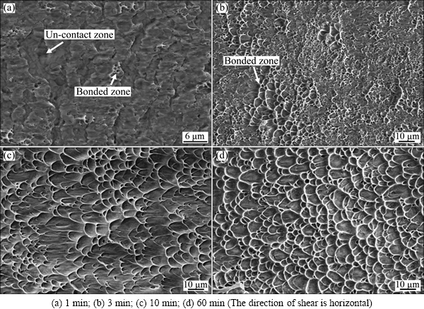
Fig. 10 SEM images of shear fracture surfaces at different bonding time
According to Fig. 7 and Fig. 9, it can be seen that the variation of shear strength of bond is similar to that of the percent of bonded area with bonding time. As the bonding time increases from 1 min to 10 min, the distinct increase of percent of bonded area promotes the increase of shear strength of bond. At 10 min, the shear strength of bond is about 867.1 MPa, which is proximate to that of the base alloy, and the corresponding percent of bonded area is about 87.0%. As the bonding time increases from 10 min to 60 min, the slight increase of percent of bonded area has a limited action on the increasing of shear strength of bond.
Based on the analysis of experimental results illustrated in Figs. 4, 6 and 9, it can be concluded that the decrease in amount and size of voids promotes the shear strength of Ti-17 titanium alloy bond. Moreover, the formation of grains across bonding interface so as to improve microstructure is also propitious to the increase of shear strength. The contribution of plastic deformation to the increase of shear strength is significant, although the action time of plastic deformation is short compared with that to obtain a bond free of void. Therefore, enhancing the action of plastic deformation in the DB process is beneficial for reducing bonding time, which will be a reference for designing and optimizing DB processing parameters.
4 Conclusions
1) In the DB process of Ti-17 titanium alloy at a bonding temperature of 860 ��C and bonding pressure of 3 MPa, the voids at the bonding interface gradually shrink and the large sized void with a scraggly edge tends to be an ellipse void with smooth surface and then changes to a tiny void with a round shape as the bonding time increases. The grains across bonding interface generate at 60 min.
2) The average size of voids at the bonding interface decreases while the amount of void decreases after increasing to the maximum value with the increase of bonding time. The size of voids becomes homogeneous with the increase of bonding time.
3) The shear strength of bond increases with the increase of bonding time. The failure model changes gradually from brittle fracture to ductile fracture. The highest shear strength of bond at 60 min is 887.4 MPa.
4) Although the action time of plastic deformation is brevity, the contribution of plastic deformation to void closure and increase in shear strength is significant in the DB of Ti-17 titanium alloy.
References
[1] MU Z, LI H, LI M Q. The microstructure evolution in the isothermal compression of Ti-17 alloy [J]. Materials Science and Engineering A, 2013, 582: 108-116.
[2] LI H, LI M Q, HAN T, LIU H B. The deformation behavior of isothermally compressed Ti-17 titanium alloy in ��+�� field [J]. Materials Science and Engineering A, 2012, 546: 40-45.
[3] ZHOU R L, GUO D L, LI C Q. TIG welding of high strength titanium alloy [J]. Welding & Joining, 2004(11): 29-31. (in Chinese)
[4] FU P F, MAO Z Y, MAO C J, LIU F J. Study on microstructure and residual stress of TC17 alloy with EBW [C]//Charged Particle Beam Source National Conference Proceedings. Wuhan: China Electrotenchnical Society, 2006: 299-301. (in Chinese)
[5] LI W Y, MA T J, YANG S Q. Microstructure evolution and mechanical properties of linear friction welded Ti-5Al-2Sn-2Zr- 4Mo-4Cr (Ti17) titanium alloy joints [J]. Advanced Engineering Materials, 2010, 12(1-2): 35-43.
[6] KURT B,  A. Interface structure of diffusion bonded duplex stainless steel and medium carbon steel couple [J]. Materials Characterization, 2009, 60: 1035-1040.
[7] LAGOS M, RETAMAL C. An alternate theoretical approach to solid-state bonding [J]. Scripta Materials, 2011, 64: 402-405.
[8] LI H, LIU H B, YU W X, LI M Q. Fabrication of high strength bond of Ti-17 alloy using press bonding under a high bonding pressure [J]. Materials Letters, 2013, 108: 212-214.
[9] ESLAMI P, KARIMI TAHERI A. An investigation on diffusion bonding of aluminum to copper using equal channel angular extrusion process [J]. Materials Letters, 2011, 65: 1862-1864.
[10] de SALAZAR J M,  Charpy impact test of Ti-6Al-4V joints diffusion welded at low temperature [J]. Scripta Materials, 1996, 35: 479-484.
[11] HAMILTON C H. Titanium science and technology [M]. New York: Plenum Press, 1973: 625-648.
[12] GARMONG G, PATON N E, ARGON A S. Attainment of full interfacial contact during diffusion bonding [J]. Metallurgical and Materials Transactions A, 1975, 6(7): 1268-1279.
[13] DERBY B, WALLACH E R. Theoretical model for diffusion bonding [J]. Metal Science, 1982, 16(1): 49-56.
[14] HILL A, WALLACH E R. Modeling solid-state diffusion bonding [J]. Acta Metallurgica, 1989, 37(19): 2425-2437.
[15] LIU Hui-jie, FENG Xui-li. Microstructures and interfacial quality of diffusion bonded TC21 titanium alloy joints [J]. Transactions of Nonferrous Metals Society of China, 2011, 21(1): 58-64.
[16] YU Yan-dong, JIANG Hai-yan, LI Qiang, ZAI Chun-quan, DING Wen-jiang. Superplasticity and diffusion bonding of magnesium alloy ZK60 [J]. Transactions of Nonferrous Metals Society of China, 2005, 15(6): 1253-1257.
[17] VIGRAMAN T, RAVINDRAN D, NARAYANASAMY R. Microstructure and mechanical property evaluation of diffusion- bonded joints made between SAE 2205 steel and AISI 1035 steel [J]. Materials & Design, 2012, 35: 156-169.
[18] WU G Q, HUANG Z. Superplastic forming/diffusion bonding of laser surface melted TiAl intermetallic alloy [J]. Scripta Materials, 2001, 45: 895-899.
[19] PILLING J, LIVESEY D W, HAWKYARD J B, RIDLEY N. Solid state bonding in superplastic Ti-6Al-4V [J]. Metal Science, 1984, 18(3): 117-122.
[20] SOMEKAWA H, WATANABE H, MUKAI T, HIGASHI K. Low temperature diffusion bonding in a superplastic AZ31 magnesium alloy [J]. Scripta Materials, 2003, 48: 1249-1254.
[21] MA R F, LI M Q, LI H, YU W X. Modeling of void closure in diffusion bonding process based on dynamic conditions [J]. Science China Technological Sciences, 2012, 55(9): 2420-2431.
[22] LI S X, XUAN F Z, TU S T. In situ observation of interfacial fatigue crack growth in diffusion bonded joints of austenitic stainless steel [J]. Journal of Nuclear Materials, 2007, 366: 1-7.
Ti-17�ѺϽ���ɢ���ӽ�����������ͷ����ǿ��
�� �꣬�� �������������Ȫ
������ҵ��ѧ ����ѧԺ������ 710072
ժ Ҫ���о���ͬ����ʱ����Ti-17�ѺϽ���ɢ���ӽ�����������ͷ����ǿ�ȡ������������������ʱ����ӳ������ӽ���ƽ���ն��ߴ���С���ն��������������ֵ�����١����о��״��Ե�IJ�����ն���ת��Ϊ����ƽ���������Բ�οն��Լ�ϸС��Բ�οն���������ʱ��Ϊ60 minʱ���ӽ������γ��˿����ӽ���ľ�������ͷ����ǿ����������ʱ����ӳ�����������ʱ��Ϊ60 minʱ����ͷ����ǿ�ȴﵽ���ֵ��Ϊ887.4 MPa���������Ա��ε�����ʱ��̣ܶ����ǶԴٽ��ն��պ��Լ���߽�ͷ����ǿ�ȵ�����������
�ؼ��ʣ�Ti-17�ѺϽ���ɢ���ӣ����ӽ��棻�ն�������ǿ��
(Edited by Xiang-qun LI)
Foundation item: Project (51275416) supported by the National Natural Science Foundation of China
Corresponding author: Miao-quan LI; Tel: +86-29-88460328; Fax: +86-29-88492642; E-mail: honeymli@nwpu.edu.cn
DOI: 10.1016/S1003-6326(15)63581-6
Abstract: The bonding interface characteristic and shear strength of diffusion bonded Ti-17 titanium alloy at different bonding time were investigated. The results show that the average size of voids decreases while the amount of voids decreases after increasing to the maximum value with the increasing bonding time. The irregular void with a scraggly edge tends to an ellipse void with smooth surface and then changes to a tiny void with round shape. The grains across bonding interface occur at bonding time of 60 min. The shear strength of bond increases with increasing bonding time, and the highest shear strength of bond is 887.4 MPa at 60 min. The contribution of plastic deformation on the void closure and the increase of shear strength is significant even though the action time of plastic deformation is short.
