
Trans. Nonferrous Met. Soc. China 23(2013) 2611-2617
Corrosion behavior of thermal sprayed WC cermet coatings containing metallic binders in saline environment
Li-jun WANG1, Pei-xian QIU1, Yan LIU1, Wu-xi ZHOU2, Guo-qing GOU1, Hui CHEN1
1. School of Materials Science and Engineering, Southwest Jiaotong University, Chengdu 610031, China;
2. Zigong Tungsten Carbide Co., Ltd. Zigong 643000, China
Received 17 July 2012; accepted 25 January 2013
Abstract:
A series of electrochemical and long-term corrosion tests were carried out in a neutral saline (5% NaCl) vapor of 35 ��C on thermal sprayed WC cermet coatings containing different kinds of metallic binders in order to examine the effect of composition of binder materials on the corrosion behavior. The experimental results revealed that the overall corrosion resistance of WC-Co coating was inferior to that of WC-Co-Cr coating. For the coatings without Cr, WC-Co, general corrosion occurred in binder materials in addition to galvanic corrosion between WC particles and metallic binders in the neutral environment. By contrast, the formation of passive film in the form of surface oxide in the coatings containing Cr, WC-Co-Cr, suppressed the binder and metallic binders to be eroded. It is found that the chemical composition of metallic binder materials is one of the important factors influencing the corrosion resistance of HVOF sprayed WC cermet coatings in the neutral vapor.
Key words:
WC-Co; WC-Co-Cr; corrosion protection; corrosion resistance; electrochemical characterization;
1 Introduction
Thermal spray coatings, and in particular those applied to the high velocity oxy-fuel (HVOF) process, are being used in a diverse range of engineering applications to extend component life by impeding wear degradation due to their excellent microstructure. Since their inception [1,2], thermal spray technologies have been the subject of some studies involving optimization of process parameters to consistently yield coatings with good bond strength, minimum residual stress and low porosity. Of several thermal spray coating materials consisting of tungsten carbide (WC) particles with metallic binders of Co or Co-Cr have been paid much attention due to their excellent combination of wear resistance and high temperature mechanical properties [3]. To apply such excellent coatings to the components used in severe and aggressive service environment [4], however, they must exhibit the acceptable corrosion resistance. Up to now, there is many systematic studies on corrosion of ship structures in marine atmosphere [5-8]; however, little information is available on the corrosion response of thermal sprayed WC cermet coatings, particularly those with metallic binders containing Cr, in such a saline vapor. Accordingly, this study provides a detailed account of the corrosion characteristics on the HVOF-sprayed WC-Co and WC-Co-Cr coatings in the saline vapor (5%) at 35 ��C. In all tests reported in this work, the corrosion behaviours of both the WC-Co and WC-Co-Cr coatings are compared under scrutiny, paying a special focus on the effect of Cr added to binder materials.
2 Experimental
Two kinds of binder materials were used in the form of composite powders with WC, and their characteristics are listed in Table 1, where no other elements exist but elements listed. Scanning electron microscopy (SEM) images of both the reference powders of WC-Co and WC-Co-Cr are shown in Fig. 1, where the powders are near-spherical with little porosity. The S45C steel (Fe-0.45C-0.35Si-0.9Mn, mass fraction, %) was used as substrate materials for two coatings and was roughened by hitting from emery before spraying. Thermal spraying coating was carried out by using a HVOF spraying system (GTV in Germany) with the processing conditions given in Table 2. The fuel was kerosene. The thicknesses of the coating layers were controlled in the range of 280-320 ��m.
The cross-sectional micrographs were observed by SEM and back scattered electron detection (BSED). SEM images of surfaces of both the coating layers were obtained. The area fraction of pores, hardness and fracture toughness of each coating layer were measured on the image analyzer, the Vickers microhardness tester (HXD 1000TM) and Vickers tester (HV-10B), respectively. The porosity was averaged from 5 measurements at different positions. The phases presented in the coating layers were identified with X-ray diffractometer (DX 2600) with Cu K�� radiation. Step scanning with a step size of 0.05�� and a scanning rate of 1 s was carried out to analyze crystalline components of the coatings.
Table 1 Characteristics of present coating materials
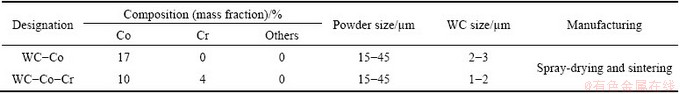
Table 2 HVOF spraying conditions

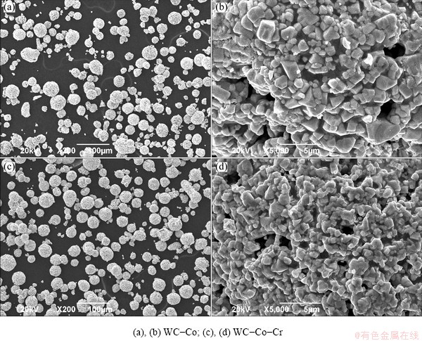
Fig. 1 SEM micrographs of both reference powders
The electrochemical behavior at 35 ��C was examined in the neutral saline of 5% NaCl with the potentiostat/galvanostat facility (LK98A). The electro- chemical tests included mainly the potentiodynamic test, which was performed at a scanning rate of 3 mV/s in the range of -1 to 1 V. Polarisation tests involved a three- electrode electrochemical cell. The saturated calomel electrode (SCE) and a platinum plate were used as a reference electrode and a counter electrode, respectively. The current in an external circuit between the specimen and a platinum counter electrode was measured as a function of potential.
The samples for electrochemical tests were encapsulated in a non-conducting epoxy resin with the rear side of the specimen soldered to a wire. The specimens were ground and polished. The specimen/ resin interface was painted with a sealing lacquer to prevent any contribution from the corrosion of the substrate via penetration of liquid down the substrate.
For the analysis on corrosive features of the coatings, each sample was exposed to the neutral 5% NaCl vapor at 35 ��C for 400 h, and then the morphologies of both the two coating layers were observed by using a JSM-6490LV SEM imager with a standard energy dispersive spectrometer (GENESS 2000XMS). Those analyzed technologies were used extensively before and after corrosion test to assess the extent and mechanisms of corrosion. The corrosion rates were calculated via Faraday��s law from the corrosion current density (Jcorr) obtained from Tafel extrapolation [9-11].
3 Results and discussion
3.1 Microstructure of coating layers
The cross-sectional microstructures of the coating layers are shown in Fig. 2. The cross-sectional micrographs with a low magnification (Figs. 2(a, c)) revealed a good adhesion between the dense coating layer and the substrate for all the specimens. High magnification images by the back scattered electron detector (BSED) (are shown in Figs. 2(b, d)). Figure 2 presents that the sprayed coating layers have a uniform and lamellar structure with a low porosity and a little bigger WC (black arrowed) due to the accumulation of the high speed molten or unmolten particles on the substrate. The semi-molten particles (fine black arrowed) and microcracks can be observed from the surface micrographs of the coating layers (Fig. 3). The high velocity impact of semi-molten coating materials on the substrate accompanies with severe plastic deformation and rapid solidification and therefore thermal spray coating layers are likely to possess inevitable pores (coarse black arrowed) and microcracks. The porosity in terms of the area fraction of pores, microhardness and fracture toughness of each layers was compared and is listed in Table 3. The porosities of both two coating layers are very low, approximately 0.9%. Previous corrosion studies [12-14] on plasma-sprayed coatings have manifested that they almost always had inherent interconnected porosity, which leads to the substrate dominating the corrosion behaviour. However, for HVOF-sprayed coatings the porosity level can be as low as 1%, as shown in Table 3, which means that interconnected porosity is no longer the main issue in the corrosion behaviour of a coating/substrate system.
Table 3 Microhardness and fraction of pores of each coating layer
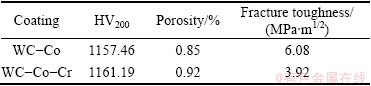
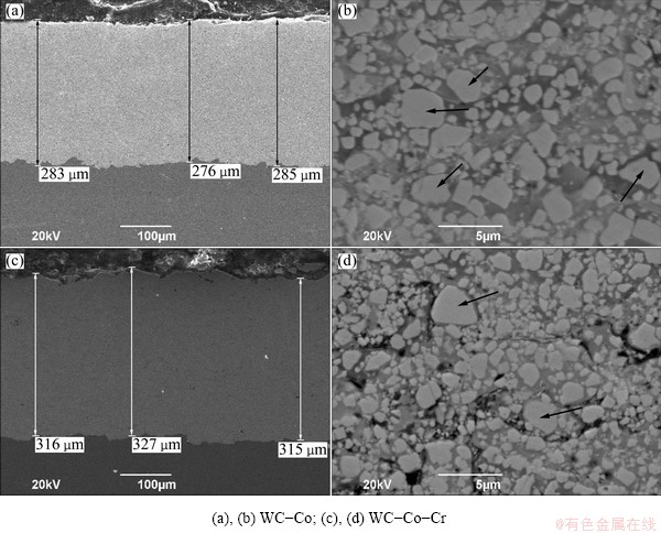
Fig. 2 Cross-sectional SEM (a,c) and BSED images (b,d) of both coating layers
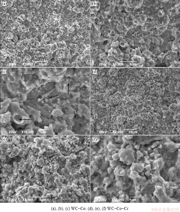
Fig. 3 SEM images of both coating layers
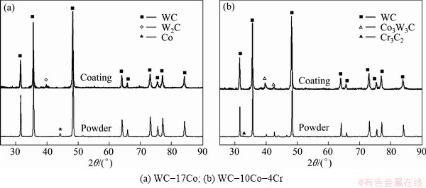
Fig. 4 XRD patterns of powders and corresponding as-HVOF sprayed coatings
Many studies have shown decarburization of WC coating powders during coating process. Figure 4 illustrates the XRD patterns of powders and the corresponding HVOF sprayed coatings. The coatings contain W2C, which was formed by the loss of carbon during spraying process. For the coating layers containing Cr, W2C was not detected. Accordingly, it is most probable that Cr in the form of Cr3C2 particles can suppress the decomposition of WC to a certain degree during high temperature spraying process.
3.2 Electrochemical behavior
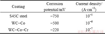
Figure 5 shows the potentiodynamic polarization curves of the present coating layers and the substrate in the 5% NaCl vapor of 35 ��C. The corrosion potential and corrosion current density of both two coating layers are shown in Table 4. It can be seen that the corrosion potential of the WC-Co-Cr coating layer (-220 mV) was higher than that of the others due to the passive phase forming effect of Cr. It can be seen that the coatings inhibited the anodic current densities prominently while the cathodic current densities were not affected substantially. Furthermore, the S45C steel showed the highest anodic dissolution rate, while the WC-10Co-4Cr coating exhibited the smallest anodic dissolution rate. The anodic dissolution rate for the WC-17Co coating fell in between two observations. Put the other way, the S45C steel showed an active corrosion behaviour, the coatings displayed an electrochemical response which is totally active initially followed by totally passive.
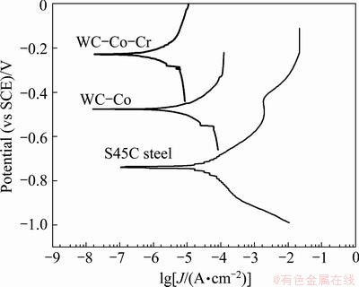
Fig. 5 Potentiodynamic polarization curves of coating layers (containing Cr or not) and substrate
Table 4 Electrochemical behavior of each coating layer and substrate
As shown in Fig. 5, the potentiodynamic polarization curves of the coating layers were similar to each other, which was different from the substrate. For the curves of the coating layers, the current density exhibited the initial exponential increase with increasing the potential and then remained nearly unchanged with further increase of potential. The corrosion potential of WC-Co-Cr (about -220 mV) was higher than that of WC-Co (approximately -500 mV). Compared to the substrate of S45C steel, the curve (the potential<-500 mV) was similar to that of the coating at active zone and then passive film formed on the surface at passive layers, that is, the substrate experienced severe corrosion zone. After that, the current density of the substrate experienced a sharp increase with the increasing of potential from just above 0.003 A/cm2 to about 0.02 A/cm2 and then remained nearly unchanged. This indicates that the substrate occurred to the spot corrosion, resulting in the destroy of the film, and experienced the severe spot corrosion again. Figure 5 shows clearly that the passive corrosion behaviour of the S45C steel substrate does not resemble to the corrosion behaviour of the coatings and the differences of the electrochemical response of the coatings arise from the different multi-phase microstructure of the corroding coatings.
3.3 Corrosion resistance
The representative SEM and BSED micrographs of the surface of each coating layer after the 400 h corrosion test (exposed to the saline vapor) are presented in Fig. 6. The considerable small pits because of WC particle isolated and protruding hard particles as matrix corrosion were observed on the surface of the coating layers without Cr while those were relatively insignificant on the surface of the coating layers containing Cr. As can be seen from Figs. 6(b) and (e) that the size of holes is approximately 2 ��m, the same as that of WC particles shown in Table 1. It is assumed that these holes formed as WC particles isolated. In the corrosion environment, a number of holes indicating the WC particles (as shown in Fig. 6(b)) showed the corrosion initiating at the carbide/metal interface (as shown in Fig. 6(c)), causing the weak adhesion between particles and matrix, and the particle isolated at last. It was reported that for the WC-Co coating layer [15], a selective dissolution of matrix firstly occurred regardless of the pH of the solution, and such local selective dissolution of matrix resulted in the WC particle isolated. In addition, the galvanic corrosion between WC particles and Co binder is expected to accelerate the WC particle isolated [16].
These microcracks were found to form in the Co-Cr binder matrix (as shown in Fig. 6(d)), where the crevice corrosion occurred easily, resulting in islands forming on the surface, thus causing the weak bond strength at the carbide/matrix interface (as shown in Fig. 6(f)). Figure 6(e) shows some pores resulting from extensive removal of the hard phases. Of the coating layers, the surface of the WC-Co-Cr coating layer (as shown in Fig. 6(d)) keeps relatively good condition even after a long corrosion time. Accordingly, it is most probable that Cr in the form of Cr3C2 particles can be dissolved into binder material during high temperature spraying process. Then, the dissolved Cr is likely to form the passive phase possessing a high potential to prevent binder materials from dissolution in the corrosion process.
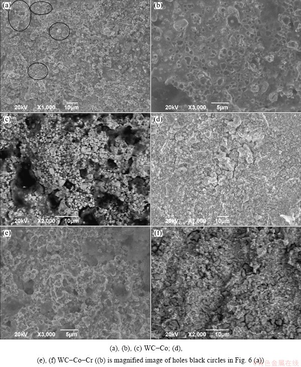
Fig. 6 Representative SEM and BSED micrographs of surfaces of both coatings after saline corrosion test
It can be concluded that the saline corrosion mechanism for both coating layers is the same as the matrix, further corrosion at the interface between WC grain and matrix would result in the loss of the WC from the binder matrix. The only difference is the corrosive rate of binder matrix of two coatings.
4 Discussion
The corrosion process is concentrated at the metallic/cermic interfaces for WC-Co coating and microcracks as crevice corrosion or/and inherent microcracks during spraying process for WC-Co-Cr coating. The potential gap between WC particles and binder matrix in WC-Co coating is bigger than that in WC-Co-Cr coating, and the interface between the WC phase and the matrix provides a site for micro-galvanic and/or crevice corrosion, thus the galvanic corrosion is more significant in WC-Co coating. Since WC hard phase particles have a very low corrosion rate [17], it is assumed that it is the metal phase attacked electrochemically in the saline vapor. Once the matrix corrodes, more prominently at the interface with the hard phase, these particles isolated with small pits left, as seen in Figs. 6(b) and (e). It is evident that once carbide removal occurred, the surface periodically becomes one of entire matrix (i.e. Co for WC-Co coating and Co/Cr for WC-Co-Cr coating) composition. The subsequent corrosion behavior will then be dependent on how fast corrosion rate to penetrate to the next layer of carbides in terms of different matrix composition. During spraying, phase transformation can result in the formation of W2C or elemental tungsten, as well as amorphous material or new phases caused by the diffusion of carbon and tungsten or added chemical elements. Thus, the multiple phases within the corroding matrix could contribute to the non-uniform rate at which it corrodes. It is found that chemical composition of metallic binder materials is the important factor influencing the corrosion resistance of the HVOF sprayed WC cermet coatings in the neutral saline vapor. The formation of new phases due to addition of new element is main element to decide the rate of corrosion on HVOF sprayed coatings.
5 Conclusions
1) The basic corrosion mechanisms of HVOF sprayed WC-Co and WC-Co-Cr in the saline vapor environment were elucidated. Corrosion at the carbide/matrix interface results in extensive removal of the hard phase.
2) The corrosion rate of the thermal sprayed coating layers is primarily determined by the composition of matrix which provides toughness and adhesion of coating. For WC cermet coatings, the addition of Cr to binder materials improved the corrosion resistance in saline environment.
References
[1] SIITONEN P, KINOS T, KETTUNEN P O. Proceedings of the 6th national thermal spray conference [C]// Boston, 1994: 105-110.
[2] THORPE R J, THORPE M L. Proceedings of the 1993 national thermal spray conference [C]//Anaheim, 1993: 7-11.
[3] LIAO H, NORMAND B, CODDET C. Influence of coating microstructure on the abrasive wear resistance of WC/Co cermet coatings [J]. Surf Coat Technol, 2000, 124(2-3): 235-242.
[4] TUCKER R C. Advanced thermal spray coatings for corrosion and wear resistance, advances in coating technologies for corrosion and wear resistant coating [C]//Warrendales, USA: TMS, 1995: 89.
[5] GUEDES SOARES C, GARBATOV Y, ZAYED A, WANG G. Influence of environmental factors on corrosion of ship structures in marine atmosphere [J]. Corrosion Science, 2009, 51: 2014-2026.
[6] GARBATOV Y, GUEDES SOARES C, WANG G. Non-linear time dependent corrosion wastage of deck plates of ballast and cargo tanks of tankers [J]. Journal of Offshore Mechanics and Arctic Engineering, 2007, 129(1): 48-55.
[7] MELCHERS R E. Effect of immersion depth on marine corrosion of mild steel [J]. Corrosion (NACE), 2005, 61(9): 895-906.
[8] MELCHERS T E. Effect of temperature on the marine immersion corrosion of carbon steels [J]. Corrosion (NACE), 2002, 58(9): 768-782.
[9] SCULLY J C. The fundamentals of corrosion [M]. Oxford: Pergamon Press, 1990.
[10] SAHA G C, KHAN T I, ZHANG G A. Erosion-corrosion resistance of microcrystalline and near-nanocrystalline WC-17Co high velocity oxy-fuel thermal spray coatings [J]. Corrosion Science, 2011, 53(6): 2106-2114.
[11] SOUZA V A D, NEVILLE A. Corrosion and synergy in a WC-Co-Cr HVOF thermal spray coating-understanding their role in erosion-corrosion degradation [J]. Wear, 2005, 259(1): 171-180.
[12] ASHARY A A, TUCKER R C. Corrosion characteristic of selected thermal spray coatings [C]//Corrosion��93. The NACE Annual Lonference. 1993: 24.
[13] ASHARY A A, TUCKER R C. Electrochemical corrosion studies of alloys plasma sprayed with Cr2O3 [J]. Surf Coat Technol, 1989, 39-40: 701-709.
[14] ASHARY A A, TUCKER R C. Electrochemical and long-term corrosion studies of several alloys in bare condition and plasma sprayed with Cr2O3 [J]. Surf Coat Technol, 1989, 43-44: 567-576.
[15] ROGNE T. The importance of corrosion on the erosion-corrosion performance of thermal spray ceramic-metallic coatings [C]//Proceedings of the 9th International Conference on Thermal Spray. Warrendale, USA: Materials Park, 1996: 207.
[16] CHO J E, HWANG S Y, KIM K Y. Corrosion behavior of thermal sprayed WC cermet coatings having various metallic binders in strong acidic environment [J]. Surf Coat Technol, 2006, 200: 2653-2662.
[17] MONTICELLI C, FRIGNANI A, ZUCCHI F. Investigation on the corrosion process of carbon steel coated by HVOF WC/Co cermets in neutral solution [J]. Corrosion Science, 2004, 46: 1225-1237.
���н������������ͿWCͿ���������еĸ�ʴ��Ϊ
������1��������1���� ��1������ϲ2��������1���� ��1
1. ���Ͻ�ͨ��ѧ ���Ͽ�ѧ�빤��ѧԺ���ɶ� 610031��
2. �Թ�����Ӳ�湫˾���Թ� 643000
ժ Ҫ���о����ѧ�ɷֶ�Ϳ����ϵ���������ʴ���ܵ�Ӱ�죬�Բ��ó����ٻ�����Ϳ�Ƶõ�WC-17Co��WC-10Co-4CrͿ����е绯ѧ����ͳ�ʱ���������ʴʵ��(Ũ��Ϊ5%��NaCl��Һ���¶�35 ��C)�����������WC-10Co-4CrͿ�����������ʴ��������WC-17CoͿ�㡣����WC-17CoͿ�㣬��Ҫ��ʴ��Ϊ����ճ������ĸ�ʴ�����WC������ճ�������֮�䷢������ż��ʴ������WC-10Co-4CrͿ�㣬�γɵ����������������ƽ�������ճ����ĸ�ʴ��˵���������ϳɷ���Ӱ�쳬���ٻ�����ͿWC��Ϳ����������ʴ���ܵ���Ҫ����֮һ��
�ؼ��ʣ�WC-17Co��WC-10Co-4Cr����ʴ��������ʴ���ܣ��绯ѧ��Ϊ
(Edited by Hua YANG)
Corresponding author: Hui CHEN; Tel/Fax: +86-28-87600625; E-mail: xnrpt@163.com; lijun-123458@163.com
DOI: 10.1016/S1003-6326(13)62775-2
Abstract: A series of electrochemical and long-term corrosion tests were carried out in a neutral saline (5% NaCl) vapor of 35 ��C on thermal sprayed WC cermet coatings containing different kinds of metallic binders in order to examine the effect of composition of binder materials on the corrosion behavior. The experimental results revealed that the overall corrosion resistance of WC-Co coating was inferior to that of WC-Co-Cr coating. For the coatings without Cr, WC-Co, general corrosion occurred in binder materials in addition to galvanic corrosion between WC particles and metallic binders in the neutral environment. By contrast, the formation of passive film in the form of surface oxide in the coatings containing Cr, WC-Co-Cr, suppressed the binder and metallic binders to be eroded. It is found that the chemical composition of metallic binder materials is one of the important factors influencing the corrosion resistance of HVOF sprayed WC cermet coatings in the neutral vapor.
