
Trans. Nonferrous Met. Soc. China 29(2019) 67-76
Effects of welding parameters on weld shape and residual stresses in electron beam welded Ti2AlNb alloy joints
Yan-jun LI1,2, Ai-ping WU1,3,4, Quan LI5, Yue ZHAO1,4, Rui-can ZHU5, Guo-qing WANG6
1. Department of Mechanical Engineering, Tsinghua University, Beijing 100084, China;
2. Beijing Institute of Radio Measurement, Beijing 100854, China;
3. State Key Laboratory of Tribology, Tsinghua University, Beijing 100084, China;
4. Key Laboratory for Advanced Materials Processing Technology, Ministry of Education, Tsinghua University, Beijing 100084, China;
5. Capital Aerospace Machinery Company, Beijing 100076, China;
6. China Academy of Launch Vehicle Technology, Beijing 100076, China
Received 29 October 2017; accepted 26 March 2018
Abstract:
In order to estimate the residual stresses in Ti2AlNb alloy jointed by electron beam welding (EBW), a computational approach based on finite element method was developed. Meanwhile, experiments were carried out to verify the numerical results. The comparison between the simulation results and measurements suggests that the developed computational approach has sufficient accuracy to predict the welding residual stress distributions. The results show that the central area of the fusion zone suffers tensile stresses in three directions. When the other parameters remain unchanged, the focus current has great impact on the weld shape and size, and then affects the residual stress level significantly. Moreover, the thick plate full-penetrated EBW weld suffers near 1000 MPa tensile stress of Z-direction in the center of the fusion zone. The wider weld has lower tensile stress in Z-direction, resulting in lower risk for cracking.
Key words:
Ti2AlNb alloy; residual stress; numerical simulation; electron beam welding;
1 Introduction
Over the past decades, Ti2AlNb-based alloys have attracted wide attention. The alloys contain a large amount of ordered orthorhombic O phase, which was firstly identified in 1988. In addition to the ordered orthorhombic O (Ti2AlNb) phase, the alloys include ��2 (hexagonal, Ti3Al), and ordered B2 (body-centered cubic) phase as well. Generally, the contents of Al and Nb in the alloys are 22-25 at.% and 20-27 at.%, respectively. Ti-22Al-23Nb (at.%), Ti-22Al-25Nb (at.%) and Ti-22Al-27Nb (at.%) [1,2] are the typical Ti2AlNb alloys. Due to the high specific strength, attractive creep and corrosion resistance, and superior processability, the Ti2AlNb alloys show great potential as structural materials in aerospace and elevated temperature fields [3,4].
To fabricate high-quality joined structures, various welding or joining processes are being developed. The processes to be developed will extend the applications of the Ti2AlNb alloys. Up to now, several welding methods have been studied to investigate the weldabilities of the Ti2AlNb alloys, including diffusion bonding [5,6], linear friction welding [7,8], laser beam welding(LBW) [9-12] and electron beam welding (EBW) [13-15]. ZOU et al [5] have studied the microstructure and strength of the joints during transient liquid phase diffusion bonding of Ti-22Al-25Nb alloy. CHEN et al [7,9] have investigated the microstructure evolution and mechanical properties of linear friction welded Ti2AlNb alloy under as-weld and post-weld heat treatment conditions. LEI et al [11,12] have investigated the microstructure evolution and tensile properties of laser welded Ti-22Al-27Nb and Ti-22Al-27Nb/TC4 joints, and CHEN et al [9] have studied the laser weldability of dissimilar Ti-22Al- 27Nb/TA15 alloys. The laser welded joints of this type of alloys show low ductility at ambient and high temperatures due to the solidification columnar structure and the O phase precipitated at the B2 grain boundaries in the welds. EBW is preferable to joining titanium alloy, because it is in much clean vacuum chamber and has high energy density and relatively low heat input [16,17] that produces a weld with narrow-deep penetration, small heat affected zone, low distortion and residual stresses. Therefore, EBW has become a preferred method of the Ti2AlNb alloys welding. TAN et al [13-15] has conducted dissimilar welding of Ti-22Al-25Nb and TC11 alloys using EBW. In their studies, hot work, such as isothermal deformation accompanied with heat treatment, has been employed to improve the microstructures and the mechanical properties of the welded joints.
It should be noted that previous studies have mainly focused on the microstructure and mechanical properties of the welded joint of the Ti2AlNb alloy, but little work has been done concerning welding-induced residual stress. In our preliminary study, the severity of crack was found to change with the weld shape in Ti2AlNb alloy thick plate EBW joints, while the microstructure distributions of these different joints were similar. The weld residual stresses were considered to be the main factor that affected the cracking. Hence, it is very important to study welding residual stress distribution in a Ti2AlNb welded joint for promoting its application in aerospace field.
2 Experimental
The base metal used in this work was hot-rolled Ti-22Al-25Nb sheet with the thickness of 5, 6.5 and 20 mm. The nominal composition of the material is: Al 22 at.%, Nb 25 at.% and balanced Ti. It was provided by Central Iron and Steel Research Institute, China. Ti2AlNb alloy plates with dimensions of 83.2 mm �� 40 mm �� 6.5 mm were butt-welded using a GENOVA 98 model EBW machine. The accelerating voltage, electron current and welding speed were 60 kV, 38 mA and 1000 mm/min, respectively, and the electron beam focused on the top surface of the specimens. During the welding process, the specimens were fixed with welding jigs in four corner regions. The residual stresses in the 6.5 mm-thick welded sample were measured with the blind-hole method.
The work-pieces with different thicknesses were performed bead-on-plate welding to study the effect of welding parameter on the cross-sectioned weld geometry. The welding conditions are shown in Table 1. The Ti2AlNb alloy plates with the thickness of 5 mm were welded using a GENOVA 98 model EBW machine, while three other machines were used for the 20 mm- thick plates: MEDARD45 (Case A), THDW-15 (Case B), and K160-G150-86-709 (Case C and Case D). A schematic diagram of welding process can be seen in Fig. 1. The appearances of the Ti2AlNb alloy welded joints were smooth (Fig. 2). No cracks or pores were observed on the surface of the weld metal. For metallographic examinations of the welds, the specimens were transversely sectioned. After mounting, grinding and polishing, the specimens were etched using a special reagent (3 mL HF, 2 mL HNO3, 7 mL H2O2 and 20 mL H2O). Meanwhile, the weld geometries obtained from the metallographic specimens were used to verify the accuracy of the calculated temperature field.
3 Finite element analysis
3.1 Geometry configuration
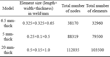
Based on ABAQUS code, a sequentially coupled thermo-elastic-plastic finite element computational approach was developed to simulate the welding temperature field and residual stresses in the EBW welded joint of Ti2AlNb alloy plate. Figure 3 shows the finite element models of work-pieces with different thicknesses used in this work. Among them, only half of the full model was used to simulate the welding of 6.5 mm-thick and 20 mm-thick work-pieces, while full model was used to that of 5 mm-thick work-piece. The dimensions of the finite element models were the same as those of the specimens used in the experiment. To balance the computing time and the calculation accuracy, element meshes were finer in the weld zone and its vicinity, while the meshes became coarser away from the weld zone. The element mesh details of different finite element models are shown in Table 2. The element types used in thermal and mechanical analyses were DC3D8 and C3D8R, respectively.
Table 1 Welding conditions for different plate thickness
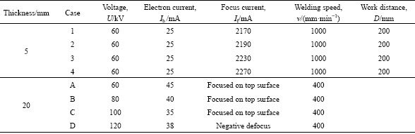
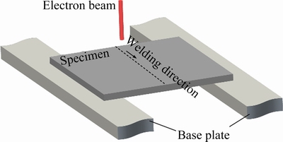
Fig. 1 Schematic diagram of bead-on-plate welding process
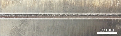
Fig. 2 Bead appearance of Case 3 welded joint
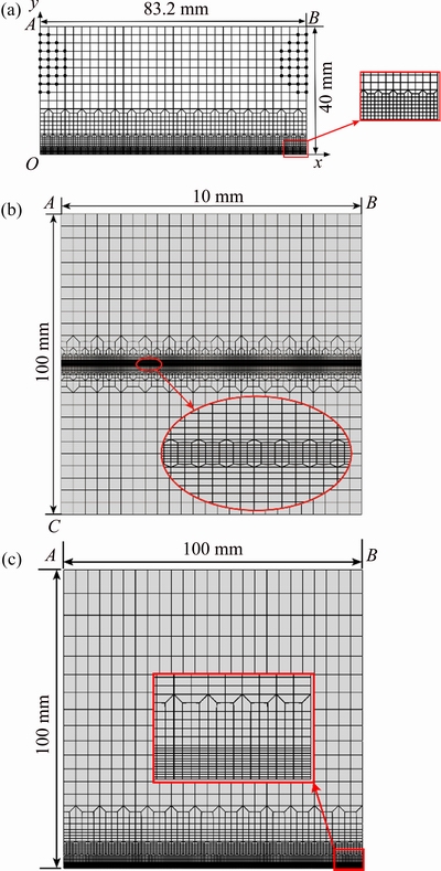
Fig. 3 Finite element models of work-pieces with different thicknesses
Table 2 Mesh details of different models
3.2 Heat source and thermal analysis
Under given welding conditions, analysis of heat flow in transient of welding was performed using the 3D finite element models with a moving heat source. Temperature-dependent thermo-physical properties of Ti2AlNb alloy is shown in Fig. 4. The thermal properties below 900 ��C were provided by Central Iron and Steel Research Institute, China, while those above 900 ��C were extrapolated. During welding, the transient temperature field is determined by solving the following non-linear heat equation:
 (1)
(1)
where �� is the density of the materials (kg/m3), c is the specific heat capacity (J/(kg����C)), T is the current temperature (��C), q is the heat flux vector (W/m2),  is the spatial gradient operator, and Q is the internal heat generation rate (W/m3). The non-linear isotropic constitutive equation of Fourier��s heat conduction was employed:
 (2)
(2)
where k is the thermal conductivity (W/(m����C)).
Accurate thermal analysis is a necessary precondition for the simulation of welding residual stress field. For the thermal analysis, the experimentally determined data were used to calibrate the heat source of the simulation. The cross-section geometry of the simulated weld pool was correlated with both the size and shape of the experimental macro-section of the weld seam for each case. In detail, a combination of two moving heat sources [18], i.e., 2D Gaussian heat source and 3D conical heat source with Gaussian distribution, was used to simulate the welding processes of all the weld cases. Subsequently, the validated temperature fields were applied to 3D simulation of the welding residual stresses.
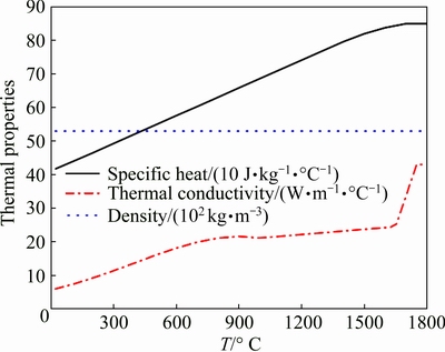
Fig. 4 Temperature-dependent thermo-physical properties of Ti2AlNb alloy
Besides, heat losses were also taken into account depending on the realistic boundary condition in the finite element model. As for the 6.5 mm-thick work- piece, radiation and heat conduction from the workpiece to fixtures were responsible for the heat loss during welding process. Meanwhile, only radiation was considered in the simulation cases of 5 mm-thick and 20 mm-thick plates, because the joints were performed without external restraint. Heat loss (qr) due to radiation was modeled using the Stefan-Boltzman law:
qr=-�Ŧ�[(Ts+273)4-(T0+273)4] (3)
where �� is the emissivity and ��=0.6 for Ti2AlNb alloy, ��=5.67��10-8 W/(m2����C), Ts is the surface temperature of the plate and T0 is the ambient temperature. It is difficult to accurately determine the heat loss (qb) through the heat conduction, because the thermal contact resistance between the workpiece and fixture is unsteady. To simplify the analysis, in the present work, the heat loss was approximately modeled using the heat flux loss by convection, and calculated using the following equations:
qb=��b(Ts-T0) (4)
��b=��kSF/d (5)
kSF=2kskf/(ks+kf) (6)
where ��b is an equivalent convection coefficient, kSF is the ideal heat conduction coefficient from the workpiece to fixture, �� is the contact factor with an estimated value of 5% based on some inverse analysis, ks is the thermal conductivity of the workpiece, kf is the thermal conductivity of the fixture, d is the element size in thickness direction which is 0.65 mm in the present model. The thermal conductivity of stainless steel (welding fixture) was considered as constant with the value of 14.3 W/(m����C) at ambient temperature, because the total heat input during welding was relatively low and did not substantially increase the temperature of the fixture.
3.3 Mechanical analysis
The mechanical analysis was conducted using the computed temperatures of thermal analysis. The finite element models employed in mechanical analysis were the same as those used in thermal analysis, except for the element type and boundary conditions. As for the simulation case of 6.5 mm-thick plate welded with fixtures, the nodes in the clamped region on the surface of the work piece were restricted in Z-direction and regained freedom after the work piece was cooled down to room temperature. The nodes in the central plane (symmetrical plane) were restricted in Y-direction as the symmetric boundary condition. Besides, points A and B were restricted in X, Y, Z directions and Z direction, respectively, for preventing rigid body motion. As for the simulation cases of 5mm-thick plate welded without clamping, only the mechanical boundary conditions to prevent rigid body motion of the work pieces were applied: point A was restricted in X, Y, Z directions, point B in Z direction, and point C in X, Z directions. In addition to those boundary conditions to prevent rigid body motion, symmetric boundary condition was also applied in the simulation cases of 20 mm-thick plates.
The alloy was presumed isotropic and Hooke��s law was applied to the elastic region, while Von Mises criterion to the plastic region using the temperature- dependent mechanical properties [17]. Figure 5 shows the temperature-dependent mechanical properties of the Ti2AlNb alloy. The mechanical properties below 900 ��C were provided by Central Iron and Steel Research Institute, China, while those above 900 ��C were extrapolated. Besides, the microstructure of the weld metal in Ti2AlNb welded joint is almost composed of single B2 phase, due to the fast cooling rate in electron beam welding process and the high content of niobium [19]. Thus, during the cooling process, there is hardly any solid phase transition happening. Therefore, the solid-phase transformation was neglected in the current mechanical model.
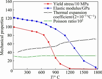
Fig. 5 Temperature-dependent mechanical properties of Ti2AlNb alloy
4 Results and discussion
4.1 Comparison between computed stress results and measurements
Figure 6 shows the weld cross-sections (peak temperature above 1750 ��C) computed by FEM and experimentally measured from the 6.5 mm-thick plate welded joint. The numerical simulation result agrees well with the experiment result. This suggests that through reasonably selecting the parameters for the developed heat source, the weld geometry computed by the current computational approach could precisely represent realistic situation. Theoretically, the thermo-elastic- plastic behavior at the elevated temperature above the melting point has very limited contribution to the final residual stress [20] because both the elastic modulus and the yield strength are close to zero. It can be inferred that the calculation accuracy of welding residual stress will not be significantly sacrificed if the size and shape of computed fusion zone are similar to those of the actual fusion zone.
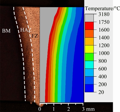
Fig. 6 Weld profile of 6.5 mm-thick plate welded joint computed and measured
To verify the prediction accuracy of the developed computational approach, the residual stress distributions on the middle cross-section measured by experiment and simulated by FEM were compared, as shown in Fig. 7. For the longitudinal and transverse residual stress distributions on the top surface of the middle cross-section, even though there were some discrepancies between the simulated and measured results in local regions, the simulated results agreed well with the experiment results in both distribution and magnitude on the whole. This indicated that the current computational approach had sufficient computing accuracy for prediction of residual stresses in Ti2AlNb EBW welded joints.
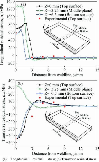
Fig. 7 Comparison of simulation and experimental residual stress distributions
4.2 Effects of welding parameters on weld shape
The fusion zones on the transverse sections of the EBW joints both computed by FEM and tested by experiments are shown in Figs. 8 and 9. There is a good agreement between them. This means that the thermal simulation models are reasonable and various welding parameters would produce different weld shapes. For the 5 mm-thick plate, the electron beam was focused on the top surface when the focus current equaled 2250 mA and the plate was full-penetrated. It can be seen from the results (Fig. 8) that the penetrated depth increases with the focus current till the plate is full-penetrated. The penetrated depths of Cases 1-4 are 2.98, 3.82, 4.48 and 5.0 mm, respectively. When the plate is thick enough, the penetration will reach the maximum when the electron beam is focused on the top surface [21]. As shown in Fig. 8, the width of the fusion zone on the top surface decreases till the focus on the top surface and then increases. The widths of the fusion zone on the top surface of Cases 1 to 4 are 2.58, 2.44, 2.06 and 2.60 mm, respectively. The weld shapes change from wedge-shape, bell-shape, to nail-shape and funnel-shape as the focus current increases. The weld with focus on the top surface would produce a nail-shape profile. The fusion cross- sectional areas of Cases 1 to 4 are 4.02, 4.35, 3.73 and 3.17 mm2, respectively.
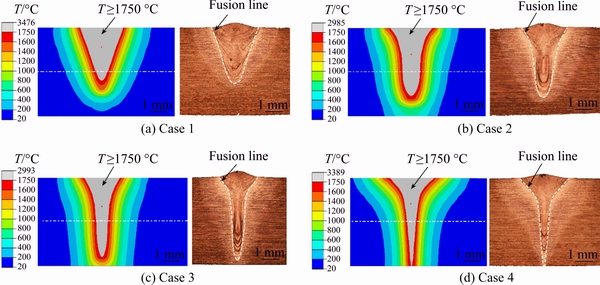
Fig. 8 Weld profiles of 5 mm-thick plate welded joints computed and measured
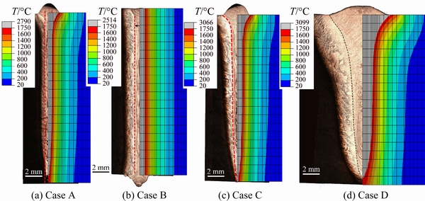
Fig. 9 Weld profiles of 20 mm-thick plate welded joints computed and measured
For the 20 mm-thick plates, with sufficient heat input and focus on the top surface, full penetrated welds are obtained, as shown in Fig. 9. The rank of weld conditions in order of heat input from the highest the to lowest is: Case D>Case C>Case B>Case A, as shown in Tabe1. As measured from the actual weld shapes, the fusion areas of Cases A to D are 16.16, 24.40, 22.73 and 46.37 mm2, respectively, and the weld widths at the middle position in thickness direction are 0.85, 1.25, 1.16 and 2.40 mm2, respectively. It is found that the weld width and fusion area increased with heat input in general, except that the relationship between Case B and Case C is a little abnormal. The difference in effective power of different welding machines might be the reason why the weld width and fusion area of Case B are a little larger than those of Case C while the heat input of Case B is less than that of Case C. In a word, the weld width and fusion area generally increase with heat input.
4.3 Effects of welding parameters on residual stresses
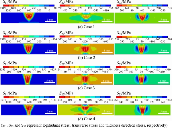
Fig. 10 Residual stress distribution on middle cross-sections of 5 mm-thick welded plates
Figure 10 shows the residual stress distributions in the three directions on the transverse sections of 5 mm- thick welded plates. As shown in Fig. 10, the residual stress distributions under different welding parameters are similar on the whole. The fusion zone and its adjacent zone suffered more than 1000 MPa of tensile longitudinal stress, other areas were subjected to compressive stress. The transverse stress has complicated distributions. The central area of the fusion zone suffered tensile stress, while on the top and bottom weld surfaces the stresses generally were compressive. However, the transverse stress on the bottom weld surface could be tensile due to the small fusion depth of the welded joint, such as Case 1. For the thickness direction, the fusion area and its adjacent zone were subjected to tensile stress, while the small area surrounding this tensile zone got compressive stress. Consequently, the central area of the fusion zone suffered tensile stresses in three directions and the funnel-shape weld had relative small values. The results indicate that the weld shape has very limited effect on the residual stress distribution on the whole.
However, the weld shape has some influence on the magnitude of the residual stress. The maximum longitudinal tensile stresses of Cases 1 to 4 are 1319, 1379, 1333 and 1271 MPa, respectively. By comparing the longitudinal stresses with the corresponding fusion areas, it is easy to find that the longitudinal tensile stress basically increases with the fusion cross-sectional area. However, the maximum longitudinal tensile stresses of Case 1 is smaller than that of Case 3, while the fusion zone of Case 1 is greater. The eccentricity of the fusion zone of Case 1 is larger, which causes a greater longitudinal defection deformation [18]. The increase in deformation can release more residual stresses and therefore the longitudinal stress of Case 1 is lower than that of Case 3. For the transverse stresses, it can be found that the maximum tensile stress generally increases with the weld width. In addition, while the weld has more uniform width in the thickness direction as well as deeper penetration, it endures larger thickness direction stress.
As shown in Fig. 11, for the 20 mm-thick welded plate, the distributions of the three direction residual stresses are similar to those of 5 mm-thick welded plate. The welds endure high longitudinal tensile stresses (above 1000 MPa) but low transverse tensile stresses (lower than 400 MPa). As the weld width and fusion area increase, the longitudinal and transverse tensile stresses go up. The rank of weld conditions in order of the maximum longitudinal or transverse stress from the highest to the lowest is: Case D > Case B > Case C > Case A .
Compared with the 5 mm-thick welded joints, the 20 mm-thick welded joints endure much higher thickness direction stresses. As shown in Fig. 11, the tensile stresses in thickness direction could exceed 1000 MPa, which are almost close to the longitudinal tensile stresses. The maximum tensile stresses in thickness direction of Case A to Case D are 1087, 1046, 1037, and 837 MPa, respectively. With a much wider weld, Case D generates lower thickness direction stress, which is probably because its inner weld metal endures less restraint in thickness direction than the other three cases during welding process.
It is noted that, welding cracks are observed in the 20 mm-thick welded plates, as illustrated in Fig. 12, but not in the 5 mm-thick welded plates. Moreover, the cracks only occur in the fusion zone and the heat affected zone where endure high residual stresses. On the other hand, while Ti2AlNb alloy is welded by high-energy beam welding, the microstructures of the welded joints are basically similar. The fusion zone is composed of single B2 phase, and the heat affected zone can be divided into three regions (single B2 phase region, ��2+B2 dual-phase region and ��2+B2+O three-phase region) due to the temperature gradient during welding [19,22]. Thus, we can infer that the high thickness direction tensile stresses are responsible for the high cracking sensitivity of the thick plate EBW. In addition, the welds of Case A to Case C crack while the Case D does not, indicating that welding cracks happen only when the thickness direction tensile stress is sufficiently high. The results show that the weld with higher heat input and wide fusion zone have lower risk for cracking, due to the lower tensile stress in thickness direction.
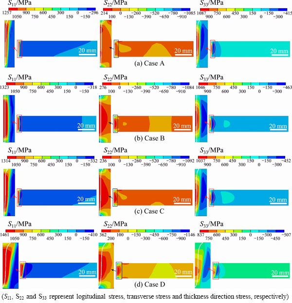
Fig. 11 Residual stress distribution on middle cross-sections of 20 mm-thick welded plates
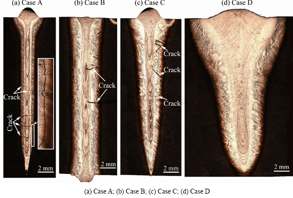
Fig. 12 Welding cracks in 20 mm-thick welded joints
5 Conclusions
(1) With the same acceleration voltage, beam current, travel speed and work distance, the focus current has great impact on the weld shape and size.
(2) EBW of Ti2AlNb produces more than 1000 MPa tensile residual stress of longitudinal direction in the fusion zone and its adjacent area. The central area of the fusion zone suffers tensile stresses in three directions.
(3) The thick plate full-penetrated EBW weld suffers near 1000 MPa tensile stress of Z-direction in the center of the fusion zone. The wider weld has relatively low tensile stress in Z-direction, resulting in low risk for cracking.
References
[1] DANG W, LI J S, ZHANG T B, KOU H C. Microstructure and phase transformation in Ti-22Al-(27-x)Nb-xZr alloys during continuous heating [J]. Journal of Materials Engineering and Performance, 2015, 24(10): 3951-3957.
[2] CHEN W, LI J W, XU L, LU B. Development of Ti2AINb alloys: Opportunities and challenges [J]. Advanced Materials & Processes, 2014, 172(5): 23-27.
[3] JIA J B, ZHANG K F, LIU L M, WU F Y. Hot deformation behavior and processing map of a powder metallurgy Ti-22Al-25Nb alloy [J]. Journal of Alloys and Compounds, 2014, 600: 215-221.
[4] KUMPFERT J, LEYENS C. Orthorhombic titanium aluminides: Intermetallics with improved damage tolerance [M]. Titanium and Titanium Alloys: Fundamentals and Applications. Wiley-VCH Verlag GmbH & Co. KGaA, 2003: 59-88.
[5] ZOU G S, XIE E H, BAI H L, WU A P, WANG Q, REN J L. A study on transient liquid phase diffusion bonding of Ti-22Al-25Nb alloy [J]. Materials Science and Engineering A, 2009, 499(1-2): 101-105.
[6] LI Bei-bei, WANG Bin, LI Ping, LIU Yu-sheng, XUE Ke-min. Solid diffusion bonding of Ti2AlNb-based alloy [J]. Transactions of Nonferrous Metals Society of China, 2015, 25(3): 662-667.
[7] CHEN X, XIE F Q, MA T J, LI W Y, WU X Q. Effects of post-weld heat treatment on microstructure and mechanical properties of linear friction welded Ti2AlNb alloy [J]. Materials & Design, 2016, 94: 45-53.
[8] CHEN X, XIE F Q, MA T J, LI W Y, WU X Q. Microstructural evolution and mechanical properties of linear friction welded Ti2AlNb joint during solution and aging treatment[J]. Materials Science and Engineering A, 2016, 668: 125-136.
[9] CHEN Y B, ZHANG K Z, HU X, LEI Z L, NI L C. Study on laser welding of a Ti-22Al-25Nb alloy: Microstructural evolution and high temperature brittle behavior [J]. Journal of Alloys and Compounds, 2016, 681: 175-185.
[10] ZHANG K Z, NI L C, LEI Z L, CHEN Y B, HU X. Microstructure and tensile properties of laser welded dissimilar Ti-22Al-27Nb and TA15 joints [J]. International Journal of Advanced Manufacturing Technology, 2016, 87(5-8): 1685-1692.
[11] LEI Z L, DONG Z J, CHEN Y B, ZHANG J, ZHU R C. Microstructure and tensile properties of laser beam welded Ti-22Al-27Nb alloys [J]. Materials & Design, 2013, 46: 151-156.
[12] LEI Z L, DONG Z J, CHEN Y B, HUANG L, ZHU R C. Microstructure and mechanical properties of laser welded Ti-22Al-27Nb/TC4 dissimilar alloys [J]. Materials Science and Engineering A, 2013, 559: 909-916.
[13] TAN L J, YAO Z K, NING Y Q, GUO H Z. Effect of isothermal deformation on microstructure and properties of electron beam welded joint of Ti2AlNb/TC11 [J]. Materials Science and Technology, 2011, 27(9): 1469-1474.
[14] TAN L J, YAO Z K, WANG T, GUO H Z. Effect of post-weld heat treatment on microstructure and properties of electron beam welded joint of Ti2AlNb/TC11 [J]. Materials Science and Technology, 2011, 27(8): 1315-1320.
[15] TAN L J, YAO Z K, ZHOU W, GUO H Z, ZHAO Y. Microstructure and properties of electron beam welded joint of Ti-22Al-25Nb/TC11 [J]. Aerospace Science and Technology, 2010, 14(5): 302-306.
[16] WANG S Q, LIU J H, CHEN D L. Tensile and fatigue properties of electron beam welded dissimilar joints between Ti-6Al-4V and BT9 titanium alloys[J]. Materials Science and Engineering A, 2013, 584: 47-56.
[17] SABOL J C, PASANG T, MISIOLEK W Z, WILLIAMS J C. Localized tensile strain distribution and metallurgy of electron beam welded Ti-5Al-5V-5Mo-3Cr titanium alloys [J]. Journal of Materials Processing Technology, 2012, 212(11): 2380-2385.
[18] LI Y J, ZHAO Y, LI Q, WU A P, ZHU R C, WANG G Q. Effects of welding condition on weld shape and distortion in electron beam welded Ti2AlNb alloy joints [J]. Materials & Design, 2017, 114: 226-233.
[19] CHEN W, CHEN Z Y, WU C C, LI J W, TANG Z Y, WANG Q J. The effect of annealing on microstructure and tensile properties of Ti-22Al-25Nb electron beam weld joint [J]. Intermetallics, 2016, 75: 8-14.
[20] BHATTI A A, BARSOUM Z, MURAKAWA H, BARSOUM I. Influence of thermo-mechanical material properties of different steel grades on welding residual stresses and angular distortion [J]. Materials & Design, 2015, 65(65): 878-889.
[21] GONG Ping. Research on the factors influenced electron beam weld shape for TC4 titanium alloy [D]. Dalian: Dalian Jiaotong University, 2007. (in Chinese)
[22] LEI Zheng-long, DONG Zhi-jun, CHEN Yan-bin, ZHOU Kai, MA Rui. Effect of heat input on the microstructures and mechanical properties of laser welded Ti2AlNb alloys [J]. Rare Metal Materials & Engineering, 2014, 43(3): 579-584.
���Ӳ�����Ti2AlNb�Ͻ���������ӽ�ͷ������״�Ͳ���Ӧ����Ӱ��
����1,2���ⰮƼ1,3,4���� Ȩ5���� �h1,4�������5��������6
1. �廪��ѧ ��е����ϵ������ 100084��
2. �������ߵ�����о��������� 100854��
3. �廪��ѧ Ħ��ѧ�����ص�ʵ���ң����� 100084��
4. �廪��ѧ �Ƚ���������������ص�ʵ���ң����� 100084��
5. �������е��˾������ 100076��
6. �й����ػ�������о�Ժ������ 100076
ժ Ҫ����������Ԫ��ֵģ�ⷽ��Ԥ��Ti2AlNb�Ͻ���������ӽ�ͷ�IJ���Ӧ������ͨ��ʵ�������֤���Ա�ģ����ʵ���������ĵ���ֵ���㷽���������õľ��ȡ�������������������������������Ӧ��״̬���������Ӳ�����ͬ�����£��۽������Ժ�����״���ߴ��������Ӱ�죬�Ӷ�Ӱ�캸�Ӳ���Ӧ��ˮƽ������Ti2AlNb�Ͻ��������������ͷ���������ľ���1000 MPa���ҵĺ�ȷ���Ӧ���������ۿ��ɽ��ͺ�ȷ���Ӧ�����������ͽ�ͷ��������
�ؼ��ʣ�Ti2AlNb�Ͻ𣻲���Ӧ������ֵģ�⣻��������
(Edited by Xiang-qun LI)
Foundation item: Project (CALT201309) supported by Joint Innovation Fund for China Academy of Launch Vehicle Technology and Colleges
Corresponding author: Yan-jun LI, Tel: +86-10-68766624, E-mail: liyanjun_thu@163.com; Yue ZHAO, Tel: +86-10-62772009, E-mail:
zhao-yue@tsinghua.edu.cn
DOI: 10.1016/S1003-6326(18)64916-7
Abstract: In order to estimate the residual stresses in Ti2AlNb alloy jointed by electron beam welding (EBW), a computational approach based on finite element method was developed. Meanwhile, experiments were carried out to verify the numerical results. The comparison between the simulation results and measurements suggests that the developed computational approach has sufficient accuracy to predict the welding residual stress distributions. The results show that the central area of the fusion zone suffers tensile stresses in three directions. When the other parameters remain unchanged, the focus current has great impact on the weld shape and size, and then affects the residual stress level significantly. Moreover, the thick plate full-penetrated EBW weld suffers near 1000 MPa tensile stress of Z-direction in the center of the fusion zone. The wider weld has lower tensile stress in Z-direction, resulting in lower risk for cracking.
