

J. Cent. South Univ. (2019) 26: 2833-2844
DOI: https://doi.org/10.1007/s11771-019-4217-1

A general analytical approach to reach maximum grid support by PMSG-based wind turbines under various grid faults
Farid Atash BAHAR1, Ali AJAMI1, Hossein MOKHTARI2, Hossein HOJABRI3
1. Department of Electrical Engineering, Azarbaijan Shahid Madani University, Tabriz, Iran;
2. Department of Electrical Engineering, Sharif University of Technology, Tehran, Iran;
3. Department of Electrical Engineering, Shahid Bahonar University, Kerman, Iran
 Central South University Press and Springer-Verlag GmbH Germany, part of Springer Nature 2019
Abstract:
A novel fault ride-through strategy for wind turbines, based on permanent magnet synchronous generator, has been proposed. The proposed strategy analytically formulates the reference current signals, disregarding grid fault type and utilizes the whole system capacity to inject the reactive current required by grid codes and deliver maximum possible active power to support grid frequency and avoid generation loss. All this has been reached by taking the grid-side converter��s phase current limit into account. The strategy is compatible with different countries�� grid codes and prevents pulsating active power injection, in an unbalanced grid condition. Model predictive current controller is applied to handling rapid transients. During faults, the energy storage system maintains DC-link voltage, which causes voltage fluctuations to be eliminated, significantly. A fault ride-through strategy was proposed for PMSG-based wind turbines, neglecting fault characteristics, second, reaching maximum possible grid support in faulty grid conditions, while avoiding over-current and third, considerable reduction in energy storage system size and power rating. Inspiring simulations have been carried out through MATLAB/SIMULINK to validate the feasibility and competency of the proposed fault ride-through method and efficiency of the entire control system.
Key words:
Cite this article as:
Farid Atash BAHAR, Ali AJAMI, Hossein MOKHTARI, Hossein HOJABRI. A general analytical approach to reach maximum grid support by PMSG-based wind turbines under various grid faults [J]. Journal of Central South University, 2019, 26(10): 2833-2844.
DOI:https://dx.doi.org/https://doi.org/10.1007/s11771-019-4217-11 Introduction
Lately, PMSG-based wind energy conversion systems (WECS) attracted more attention thanks to their inherent merits like less maintenance cost according to gearbox removal [1], more power density and lumped structure, except for their initial installation cost [2, 3].
While wind energy gains a more sever role in total power generation [4, 5], grid authorities asked wind power plants to contribute more in transients, like conventional power plants [6]. They stated regulations called grid codes [7], in which the capability to ride-through grid fault is requested, like asking the WECS to remain connected in abnormal grid conditions and next, WECS should provide ancillary service to the grid [7, 8].
The required reactive current by German grid code relative to voltage drop level can be seen in Figure 1. Grid codes are mostly set to aim only positive sequence reactive current injection, neglecting the fact that asymmetric faults are from absolute majority [9]. This will boost not only positive sequence voltage, but also causes a boost in negative and zero sequence voltages, too [10]. In order to overcome this problem and driving the unbalanced grid voltages toward balanced ones, negative sequence current injection alongside with positive sequence current is inevitable [10]. Also, this is needed to mitigate pulsating active power injection.
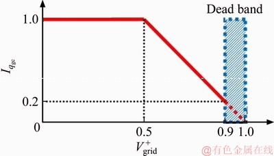
Figure 1 Required reactive current considering voltage sag level in German grid code [7]
Uninterrupted power generation leads to extra active power burden in DC-link and will result in DC over-voltage [11]. Because, grid-side converter (GSC) cannot deliver the whole generated power by reaching current protection limit [12].
Usually, additional protection devices such as braking chopper (BC) and energy storage system (ESS) are utilized in a hybrid manner to help with this issue [13]. But, normally the ESS is used to smoothen the generator output power [13, 14], which is stipulated in IEEE P2030.2 standard [15]. Also, power oscillation damping can be assigned to ESS [16]. But ESS not only can smoothen the generator output power, but also will improve the FRT capability of the WT. A fault ride-through (FRT) strategy is about how a WT contributes to the faulty grid. Therefore, proposing a strategy, which analytically defines the current references, would be of a great interest, especially when completely respects grid code requirements (GCR) and provides maximum possible grid support during fault. Some of the released strategies do not lie on analytical basis [8, 17] and the formulations in Refs. [2, 3, 18] are complicated and implicit. In some others, GCRs are not completely taken into account and current references are defined according to pre-defined power references [17, 19�C 22], missing the fact that in grid codes just reactive current amount is mentioned, not reactive and active power references. In some of the strategies like Refs. [8, 13, 20, 23] the injected currents are balanced and in the case of asymmetrical faults, pulsating active power is injected to the grid. Also, injecting just positive sequence reactive current may lead to over-voltage [10].
Methodology in Ref. [13] does not support grid frequency by injecting active power. DC-link voltage control is very important in FRT strategy, because the surplus undeliverable active power should be treated, which is not mentioned in Refs. [8, 17, 18, 20, 21]. In these methodologies, stabilized DC-link voltage is taken as granted and no effective solution is offered to control DC-link voltage during fault. Also in Refs. [2, 11], DC-link voltage control is maintained by machine-side converter (MSC) that has some major drawbacks [24]. Another important aspect is to maintain phase currents amplitude in acceptable margin, which is missed in some cases [11, 17, 21].
In this paper an FRT strategy based on analytical approach is proposed that utilizes the whole system capacity to serve maximum possible ancillary service by injecting required reactive current and delivering maximum allowed amount of active power. This is a key point, because in real world, preventing generation loss and maintaining grid frequency is severely concerned [24]. The unbalanced current references for GSC are calculated explicitly by crystal clear formulation, which completely comply with GCRs and respect phase current limitation and by injecting them, no oscillating active power flows to the grid. During fault, the DC-link voltage control is transferred from GSC to ESS resulting in mitigation of DC-link voltage oscillation. In this FRT strategy, the ESS power rating and size is considerably reduced in comparison to Ref. [13].
This paper is organized as fallows. Section 2 is dedicated to formulate current reference signals. Section 3 is about description of coordinated controller for GSC, BC and ESS. Numerical examples and simulation results are presented in Section 4 in order to validate the obtained equations and to show the effective performance of the proposed strategy under different faulty conditions. Also, a brief conclusion is presented in Section 5.
2 Proposed strategy
A typical PMSG-based WECS consists of three main equipments: a wind turbine, PMSG and a back-to-back (BTB) converter. The configuration of a PMSG-based wind turbine (WT) accompanied by BC and ESS is depicted in Figure 2.
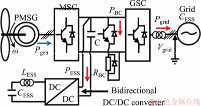
Figure 2 PMSG-based WT configuration with ESS and BC
Grid codes want WECS to inject special amount of reactive current, respecting positive voltage drop level. German grid code requires reactive current injection by WT, as:
 (1)
(1)
where Iqgc and  are the demanded reactive current and sagged positive sequence grid voltage amplitude, respectively.
Interaction between positive and arisen negative sequence voltages and currents results in more complicated power terms, in comparison with balanced condition. In the unbalanced condition, apparent power (S) is expressed as:

 (2)
(2)
where d and q subscripts stand for direct and quadrature components.
Above multiplication can be rewritten in matrix form, which leads in active and reactive power components definition just like:
 (3)
(3)
where
 (4)
(4)
Oscillating term with double grid frequency lies on average active and reactive powers, as can be seen from Eq. (4).
Locking positive and negative sequence reference frames to positive and negative sequence voltage vectors makes the q component of both positive and negative sequence voltages to become zero. This results in calculation and controller design simplification 
 and
and 
Through Park transformation, unbalanced reference currents will turn into d-q components of positive and negative sequences reference frames, as:
 (5)
(5)
 (6)
(6)
The rotating space vectors, I+ and I�C related to stationary ���� frame, are illustrated in Figure 3.
Now, average active and reactive powers just contain d and q current components, respectively and besides, Pc2 (and Qs2) and Ps2 (and Qc2) are dependent to only d and q current components, respectively:
 (7)
(7)
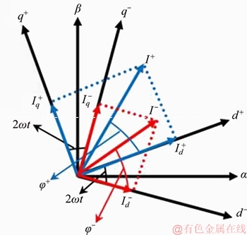
Figure 3 Positive and negative sequence currents projection on synchronous reference frames toward stationary ���� frame
The priority is maintaining oscillatory active power as zero, like:
 (8)
(8)
 (9)
(9)
From Eqs. (8) and (9), two helpful auxiliary relations are derived, which will be applied next:
 (10)
(10)
 (11)
(11)
The and
and values are defined according to Eq. (11) and considering required reactive current by grid code, like below:
 (12)
(12)
In grid codes, Iqgc is defined just considering the positive sequence voltage  while
while is present in equations. Then arrangement of the current components, which realizes the maximum grid support, is unique. In this method, first it is assumed that there is a suitable set of unbalanced currents, which in interaction with unbalanced (sagged) grid voltages satisfies the upcoming three conditions:
1) The required reactive current is provided.
2) The oscillating active power flow is zero.
3) During voltage sag, maximum possible active power is delivered to the grid without over- current.
The main goal is to obtain the rated phase currents in terms of positive and negative d-q current components. Hence, using inverse Park transformation, the phase currents should be stated in terms of d-q components, like:
 (13)
(13)
 (14)
(14)
Now, the resultant phase currents are formed like as below:
 (15)
(15)
Expanding first row of above-mentioned set, with considering Eqs. (13) and (14), leads to:
 (16)
(16)
The summation of a ��sin�� term and a ��cos�� term can turn into just one new ��cos�� term. The amplitude and phase angle are calculated by the following simple trigonometric rule:
 (17)
(17)
Applying above mentioned rule to Eq. (16) gives:

 (18)
(18)
The radical formed coefficient of ��cos�� function, is in fact the phase ��a�� current amplitude resulted from specific and
and  Now it is clear that the phase current amplitude must be less than rated phase current, like:
 (19)
(19)
With considering Eq. (10), expanding and simplifying Eq. (19) results in
 (20)
(20)
 (21)
(21)
where  is the d component of the three phase currents formed by positive and negative d-q components and
  is the maximum value for
 together with other current components (defined by Eqs. (10) and (12)) will bring the phase ��a�� current to the over-current threshold.
Putting in first row of Eq. (7) and taking Eq. (10) into account, define the maximum deliverable active power to the grid without over-current occurrence in phase ��a��, like:
 (22)
(22)
The first step to calculate is to expand second row of Eq. (15), with considering Eqs. (13) and (14):

 (23)
(23)
Expanding Eq. (23) and taking out the cos(��t) and sin(��t) factors, will lead to Eq. (24).

 (24)
(24)
Adopting Eq. (17) for (24) and simplifying the output, turns to Eq. (25).


 (25)
(25)
In Eq. (25), the ��tan�C1�� arguments is not mentioned, as it is so lengthy and will not be used in further calculations. Now the phase ��b�� current amplitude should be less than current protection limit.

 (26)
(26)
With considering Eq. (10), expanding Eq. (26) results in:
 (27)
(27)
 (28)
(28)
can be calculated from putting  in first row of Eq. (7) and taking Eq. (10) into account:
 ��
��
 (29)
(29)

 and
and (related to phase ��c��) have the same equations as for phase ��b��, like:
 (30)
(30)
 (31)
(31)

(32)
After calculating all values (x=a, b and c), the limiting is the smallest value, because delivering this much active power to the grid will bring at least one of the phases to the current protection limit, depending on fault condition. Now the maximum possible capacity of the GSC will be utilized, while the demanded reactive current in GCRs is injected to the faulty grid. Also injected oscillating active power is zero. Choosing the limitingas active power reference and holding Eq. (10) in hand, will lead to a system of linear equations which gives out the
 and
and as Eq. (33) and also
  and
and  will be like Eq. (34):
 (33)
(33)
 (34)
(34)
Now the four reference values of the current components

 and
and are calculated precisely and are ready to be fed to GSC�� current controller.
By injecting maximum possible active power, a part of the WT��s generated power is handled, which can help reducing the ESS size and power rating. Because, the amount of non-deliverable power is reduced, then a smaller ESS with less power rating can handle the excess power in collaboration with BC. This idea is one of the contributions in the proposed method. The cost of establishing a high power ESS is too high, and conventionally it is preferred to choose the ESS power rating as 0.3 of the wind turbine rated power [11]. But in this strategy, the ESS power rating is chosen as 0.1 instead of 0.3.
3 Coordinated control of GSC, ESS and BC
As can be seen in Figure 4(a), in a faulty grid condition, the GSC�� controller generates currents according to reference signals obtained previously. The ESS is used to smoothen the generator��s output power in normal condition and to control DC-link voltage during grid faults, where GSC gives up this task to it. These two control loops are shown in Figure 4(b).
The ESS has two control loops. The outer loop stabilizes DC-link voltage by generating the reference value for inner current loop. The inner control loop regulates ESS�� current to its reference value. ESS power is calculated from ESS current and voltage (IESS and VESS), as follows:
 (35)
(35)
In order to control ESS�� current, the voltage of the DC/DC converter��s boost inductance (VL) should be inspected:
 (36)
(36)
where LESS and DESS are boost inductance and duty cycle of bidirectional DC/DC converter, respectively. The duty cycle can be described as:
 (37)
(37)
When in a faulty grid condition, the ESS cannot absorb whole extra power and ESS capacity reaches its saturation, BC is activated to shoulder the rest of the task, treating residue surplus power, like:
 (38)
(38)
The duty cycle of the S3 switch in the braking chopper (see Figure 4(b)), is calculated as:
 (39)
(39)
where RBC is braking resistor.
4 Operation analysis and simulation results
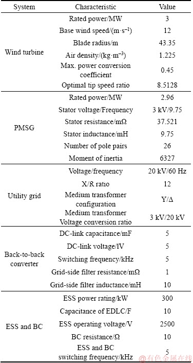
In order to verify the feasibility and effectiveness of the proposed FRT strategy, three different simulation scenarios for FRT of a 3 MW PMSG-based WT, including two asymmetric and one symmetric faults, were performed and results are discussed. The simulations are implemented in MATLAB/SIMULINK environment with a solution time step of 1 ��s. All faults occur in 0.6 s to 1 s time interval. System characteristics can be found in Table 1.
4.1 First scenario: ��-g fault at PCC
In this scenario, ��-g fault at PCC (phase ��b��),turns WT connection bus voltages unbalanced like: Va=1587.9 V, Vb=1471.8 V and Vc=2445.4 V. In this way, positive and negative sequence voltages will be  1753.4 V and
  693.9 V. According to German grid code, 0.5680 reactive current should be injected to the grid during the fault and then, applying Eq. (34) gives:
  332.38 A and
  131.54 A.Calculated and
  are 1310.01 A and 2.909 kW, respectively. As exceeds GSC�� current capacity, then it cannot be chosen as
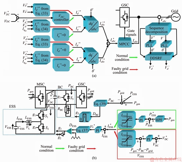
Figure 4 GSC controller block diagram (a) and ESS and BC controllers block diagram (b)
On the other hand, calculated and  are 564.93 A and 1.253 kW, respectively (same for phase ��c��). Consequently,
  is chosen as 564.93 A and
  will be 223.57 A. In this way, 1.253 MW active power will flow into grid (out of 2.124 MW generated power). As the extra power (871 kW) exceeds ESS power capacity, 300 kW (0.1) of that is absorbed by ESS and 571 kW, dissipated by BC.
The simulation results for this case are illustrated in Figure 5. Figure 5 shows good performance of the controller, ESS, BC and overall system together with the proposed strategy. The synthesized current components follow their reference values, accurately and the grid currents, injected by the GSC, are like: Ia=787.09 A, Ib=817.20 A and Ic=390.93 A. The phase ��b�� has reached its current protection limit and other phase currents reside in GSC��s tolerable margin, which indicates the proper operation of the applied strategy in calculating reference currents.
As can be seen, the generated active power is fully handled during fault without over-voltage occurrence in DC-link despite ESS size and power rating reduction and the maximum deliverable active power is injected to the grid, avoiding over-current. The ESS and BC have successfully treated the extra non-deliverable active power by absorbing and dissipating it, following their reference values. The ESS maintains the DC-link voltage at its reference value (5 kV), properly and reduces voltage oscillations significantly.
Table 1 System characteristics
4.2 Second scenario: 2�ըCg fault at PCC
WT connection bus voltages are asymmetric as: Va=897.2 V, Vb=1626.9 V and Vc=1813.2 V, resulting in: 1402 V and 531 V. The required reactive current will be 0.8553 p.u. and  and
and  will be 505.25 A and 191.36 A. In this way, and have unacceptable values of 1213.55 A and 2.186 MW, but and are calculated as 427.62 A and 770 kW. Choosing and as 427.62 A and �C161.96 A, guaranties delivering maximum possible active power to grid during the fault without over-current occurrence. Consequently 770 kW active power will be delivered to grid and 300 kW out of extra non-deliverable power (1.354 MW) is absorbed by ESS and the rest, 1.054 MW, is wasted by BC. Simulation results for this scenario are shown in Figures 6(a1)�C(a8), where the d�Cq components of positive and negative sequence currents yield on their reference value and injected currents to the grid are like: Ia=815.82 A, Ib=577.91 A and Ib=466.64 A. In this case phase ��a�� has reached the current protection threshold. The mismatched active power is treated and current components satisfy GCRs without current threshold violation. Hence, the DC-link voltage is maintained around 5 kV, accurately without considerable fluctuations.
4.3 Third scenario: 3�ըCg fault at PCC
In this scenario, a symmetric fault happens at PCC which drops the phase voltages to 1707.5 V, equally. So, will be 1707.5 V and
 will remain zero. Now, the WT is supposed to inject 494.53 A (0.6056 p.u.) reactive current. As has zero value, then will be 494.53 A and
  0 A.
0 A.  and
and  have the same value for all three phases. Taking phase ��a�� into account, and will be 649.90 A and 1.664 MW. Under this condition 1.664 MW active power will be delivered to the grid and rest of the generated power is handled by ESS (300 kW) and BC (160 kW).
Figures 6(b1)�C(b8) show the simulation results for the third scenario. The current components are injected to the grid respecting their reference value and phase currents are measured as Ia=815.31 A, Ib=816.91 A and Ic=816.99 A. As it is obvious, all the phases reached GSC��s rated current due to symmetric nature of the fault. The mismatched active power is fully treated by ESS and BC and the ESS maintained the DC-link voltage at its reference value properly without oscillation.
5 Conclusions
In this paper a novel and efficient FRT strategy has been proposed for PMSG-based WTs, during grid faults and unbalanced current reference signals are calculated by clear analytical approach in accordance with GCRs, without pulsating active power injection. The proposed strategy offers maximum possible grid support by exploiting the whole GSC capacity during faults to fulfill GCRs by injecting required reactive current and injecting the most deliverable active power while avoiding over-current. This prevents generation loss and maintains frequency support as much as possible, during fault interval.
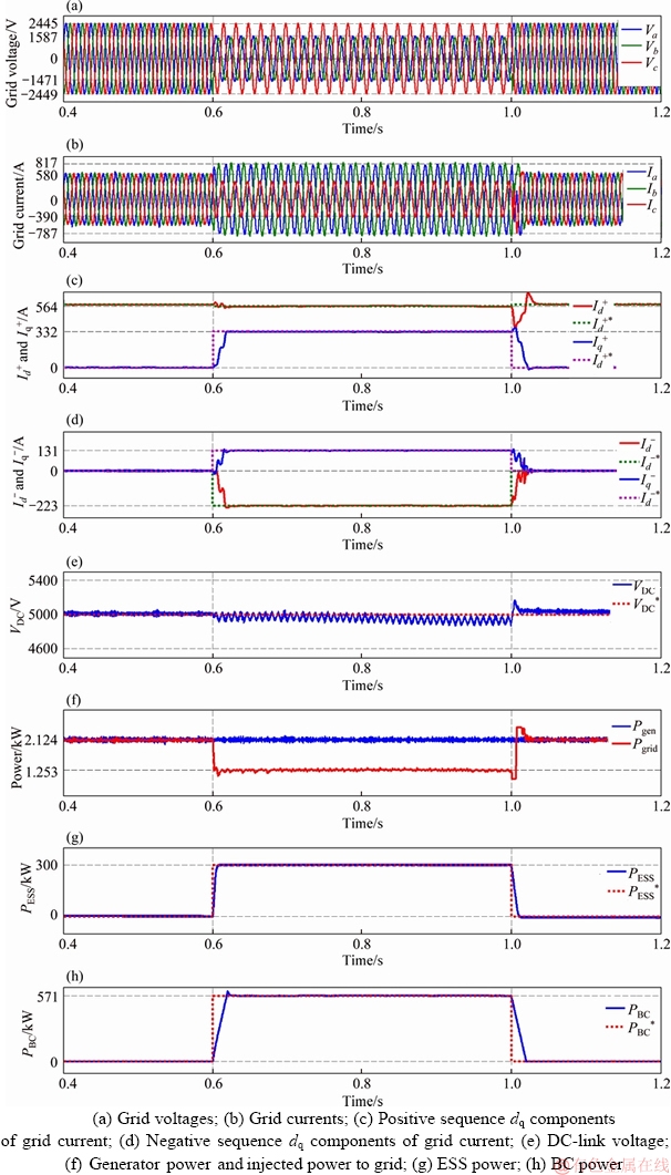
Figure 5 Simulation results for first scenario:
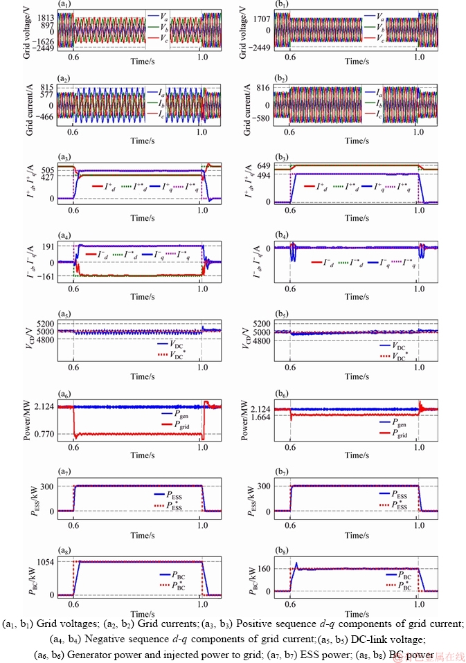
Figure 6 Simulation results for second scenario (a) and third scenario (b):
Reducing ESS power rating makes it more affordable, without causing any drawbacks on its performance. The reduced-size ESS properly controls DC-link voltage during faults and reduces DC-link voltage oscillatory term to almost as negligible.
Three different scenarios including asymmetric and symmetric faulty grid conditions have been analytically presented, discussed and simulated to confirm the validity and effectiveness of the proposed FRT strategy.
The main contributions of the proposed FRT strategy can be summarized as below:
1) Presenting a comprehensive FRT strategy for PMSG-based WTs neglecting fault characteristics.
2) Reaching maximum possible grid support while avoiding over-current.
3) Considerable reduction in ESS size and power rating.
4) Fast FRT accommodation according to ESS�� role and avoiding slow mechanical solutions.
5) Attaining constant DC-link voltage and zero oscillating active power injection, simultaneously, while not draining oscillating power from turbine.
6) Fulfilling FRT demands and providing maximum grid support without increasing BTB converter��s nominal ratings, in contrast with a real world-implemented FRT strategy.
References
[1] ARANI M F M, MOHAMED Y A I. Assessment and enhancement of a full-Scale PMSG-based wind power generator performance under faults [J]. IEEE Transactions on Energy Conversion, 2016, 31(2): 728�C739. DOI: 10.1109/ TEC.2016.2526618.
[2] NASIRI M, MOHAMMADI R. Peak current limitation for grid side inverter by limited active power in PMSG-based wind turbines during different grid faults [J]. IEEE Transactions on Sustainable Energy, 2017, 8(1): 3�C12. DOI: 10.1109/TSTE.2016.2578042.
[3] YASSIN H M, HANAFY H H, HALLOUDA M M. Enhancement low-voltage ride through capability of permanent magnet synchronous generator-based wind turbines using interval type-2 fuzzy control [J]. IET Renewable Power Generation, 2016, 10(3): 339�C348. DOI: 10.1049/iet-rpg.2014.0453.
[4] GAO Q, CAI X, GUO X, MENG R. Parameter sensitivities analysis for classical flutter speed of a horizontal axis wind turbine blade [J]. Journal of Central South University, 2018, 25(7): 1746-1754. DOI: 10.1007/s11771-018-3865-x.
[5] RAVADANEGH S N, OSKUEE M R J, KARIMI M. Multi-objective planning model for simultaneous reconfiguration of power distribution network and allocation of renewable energy resources and capacitors with considering uncertainties [J]. Journal of Central South University, 2017, 24(8): 1837-1849. DOI: 10.1007/s11771- 017-3592-8.
[6] HANSEN A D, MICHALKE G. Multi-pole permanent magnet synchronous generator wind turbines�� grid support capability in uninterrupted operation during grid faults [J]. IET Renewable Power Generation, 2009, 3(3): 333�C348. DOI: 10.1049/iet-rpg.2008.0055.
[7] Grid Code. High and Extra High Voltage [M]. Germany: E.ON Netz GmbH, Bayreuth, 2006.
[8] TEODORESCU R, LISERRE M, RODRIGUEZ P. Grid converters for photovoltaic and wind power systems [M]. New Jersy: Wiley-IEEE Press, 2011.
[9] ANDERSON P M. Analysis of faulted power systems [M]. NewYork: USA, IEEE Press, 1995.
[10] GOKSU O, TEOSORESCU R, BAK C L, IOV F, KJAER P C. Impact of wind power plant reactive current injection during asymmetrical grid faults [J]. IET Renewable Power Generation, 2013, 7(5): 484�C492. DOI: 10.1049/iet-rpg. 2012.0255.
[11] KIM K H, JEUNG Y C, LEE D C, KIM H G. LVRT scheme of PMSG wind power systems based on feedback linearization [J]. IEEE Transactions on Power Electronics, 2012, 27(5): 2376�C2384. DOI: 10.1109/TPEL.2011.2171999.
[12] GENG H, YANG G, XU D, WU B. Unified power control for PMSG-based WECS operating under different grid conditions [J]. IEEE Transactions on Energy Conversion, 2011, 26(3): 822�C830. DOI: 10.1109/TEC.2011.2127478.
[13] NGUYEN T H, LEE D C. Advanced fault ride-through technique for PMSG wind turbine systems using line-side converter as STATCOM [J]. IEEE Transactions on Industrial Electronics, 2013, 60(7): 2842�C2850. DOI: 10.1109/ TIE.2012.2229673.
[14] UEHARA A, PRATAP A, GOYA T, SENJYU T, YONA A, ARASAKI N, FUNABASHI T. A coordinated control method to smooth wind power fluctuations of a PMSG-based WECS [J]. IEEE Transactions on Energy Conversion, 2011, 26(2): 550�C558. DOI: 10.1109/TEC.2011.2107912.
[15] IEEE Standard 2030.2. Interoperability of energy storage systems integrated with the electric power infrastructure [S]. 2015.
[16] XU G, XU L, MORROW J. Power oscillation damping using wind turbines with energy storage [J]. IET Renewable Power Generation, 2013, 7(5): 1�C8. DOI: 10.1049/iet-rpg.2012. 0019.
[17] ALEPUZ S, BUSQUETS-MONGE S, BORDONAU J, MARTINEZ-VELASCO J A, SILVA C A, PONTT J, RODRIGUEZ J. Control strategies based on symmetrical components for grid-connected converters under voltage dips [J]. IEEE Transactions on Industrial Electronics, 2009, 56(6): 2162�C2173. DOI: 10.1109/TIE.2009.2017102.
[18] SHABESTARY M M, MOHAMED Y A I. An analytical method to obtain maximum allowable grid support by using grid-connected converters [J]. IEEE Transactions on Sustainable Energy, 2016, 7(4): 1558�C1571. DOI: 10.1109/TSTE.2016.2569022.
[19] SHIN D, LEE K, LEE J, YOO D W, KIM H J. Implementation of fault ride-through techniques of grid-connected inverter for distributed energy resources with adaptive low-pass notch PLL [J]. IEEE Transactions on Power Electronics, 2015, 30(5): 2859�C2871. DOI: 10.1109/TPEL.2014.2378792.
[20] CALLE-PRADO A, ALEPUZ S, BORDONAU J, NICOLAS-APRUZZESE J, CORTES P, RODRIGUEZ J. Model predictive current control of grid-connected neutral-point-clamped converters to meet low-voltage ride-through requirements [J]. IEEE Transactions on Industrial Electronics, 2015, 62(3): 1503�C1514. DOI: 10.1109/TIE.2014.2364459.
[21] JUNYENT-FERRE A, GOMIS-BELLMUNT O, GREEN T C, SOTO-SANCHEZ D E. Current control reference calculation issues for the operation of renewable source grid interface VSCs under unbalanced voltage sags [J]. IEEE Transactions on Power Electronics, 2011, 26(12): 3744�C3753. DOI: 10.1109/TPEL.2011.2167761.
[22] MOAWWAD A, EL-MOURSI M S, XIAO W. A novel transient control strategy for VSC-HVDC connecting offshore wind power plant [J]. IEEE Transactions on Sustainable Energy, 2014, 5(4): 1056�C1069. DOI: 10.1109/TSTE.2014.2325951.
[23] YARAMASU V, WU B, ALEPUZ S, KOURO S. Predictive control for low-voltage ride-through enhancement of three-level-boost and NPC-converter-based PMSG wind turbine [J]. IEEE Transactions on Industrial Electronics, 2014, 61(12): 6832�C6843. DOI: 10.1109/TIE.2014.2314060.
[24] NELSON R J, MA H, GOLDENBAUM N M. Fault ride-through capabilities of siemens full-converter wind turbines [C]// IEEE Power and Energy Society General Meeting. Detroit, USA: IEEE, 2011: 12303742. DOI: 10.1109/PES.2011.6039729.
(Edited by HE Yun-bin)
���ĵ���
һ������ͬ������������ڵ��������´ﵽ����ȵ���֧�ֵ�ͨ�÷�������
ժҪ�������һ�ֻ�������ͬ��������ķ�����������Ϲ��߲��ԡ��ò��Բ����ǵ����������ͣ��Բο������źŽ����˽������㣬����������ϵͳ��������ע�������������������������������ܵ��й�������֧�ֵ���Ƶ�ʣ����ⷢ����ġ�������Щ����ͨ�����ǵ�����任������������ƶ�ʵ�ֵġ��ò��������ڲ�ͬ���ҵĵ������룬�ڵ�����ƽ�������£���ֹ�������й����ʵ�ע�롣ģ��Ԥ��������������ڴ�������˲�䡣�ڹ����ڼ䣬����ϵͳ����DC���ӵ�ѹ������������ѹ���������������һ�ֻ�������ͬ������ķ�������Ϲ��˲��ԣ������˹������ԣ���Σ��ڵ������ϵ�����´ﵽ�����ܵĵ���֧�֣�ͬʱ���������������������Ƚ��ʹ���ϵͳ�Ĺ�ģ�Ͷ���ʡ�ͨ��MATLAB/SIMULINK���棬��֤�˸÷����Ŀ����Ժ;�������������������ϵͳ��Ч�ʽ����˷��档
�ؼ��ʣ��������棻���Ż�������ϵͳ���ϣ�Ԥ����ƣ���������
Received date: 2017-04-25; Accepted date: 2018-10-20
Corresponding author: Ali AJAMI, PhD, Professor; Tel: +98-914-3183362; E-mail: ajami@azaruniv.ac.ir; ORCID: 0000-0003-3906- 5162
Abstract: A novel fault ride-through strategy for wind turbines, based on permanent magnet synchronous generator, has been proposed. The proposed strategy analytically formulates the reference current signals, disregarding grid fault type and utilizes the whole system capacity to inject the reactive current required by grid codes and deliver maximum possible active power to support grid frequency and avoid generation loss. All this has been reached by taking the grid-side converter��s phase current limit into account. The strategy is compatible with different countries�� grid codes and prevents pulsating active power injection, in an unbalanced grid condition. Model predictive current controller is applied to handling rapid transients. During faults, the energy storage system maintains DC-link voltage, which causes voltage fluctuations to be eliminated, significantly. A fault ride-through strategy was proposed for PMSG-based wind turbines, neglecting fault characteristics, second, reaching maximum possible grid support in faulty grid conditions, while avoiding over-current and third, considerable reduction in energy storage system size and power rating. Inspiring simulations have been carried out through MATLAB/SIMULINK to validate the feasibility and competency of the proposed fault ride-through method and efficiency of the entire control system.
