

Simulation of local effect of reinforcement on temperature field during solidification of aluminum metal matrix composite
FU Yu-bi(�����), ZHANG Xue-xi(��ѧϰ), WANG De-zun(������)
School of Materials Science and Engineering, Harbin Institute of Technology, Harbin 150001, China
Received 28 July 2006; accepted 15 September 2006
Abstract:
The effect of reinforcement on the solidification of pure metal matrix composites (MMCs) was simulated using a two-dimensional solidification temperature field model by the finite element method. The concept of the character length was proposed to describe the size of reinforcement local heat influential zone in MMCs solidification according to the change of the morphologies of solid-liquid interface. The relationship between the character length and the geometrical conditions, the boundary condition and physical properties of the reinforcement were studied, respectively. The results show that the width of the unit and the cold boundary temperature have no effect on the character lengths but have effect on the distance between cold boundary and reinforcement (l) and the thermal parameters of the reinforcement. An experimental rule to predict the value of the character length was derived and applied.
Key words:
metal matrix composites (MMCs); numerical simulation; temperature field; finite element method; solidification;
1 Introduction
The solidification microstructure of metals decides their property and performance. So, how to control the solidification microstructure of metal matrix composites (MMCs) is crucial to material fabrication process. Experimental investigations of the microstructure of MMCs, such as the relationship between the two phases[1], reinforcement distribution[2] and defects, were done abundantly[3-12]. However, few theoretical researches were done in this area. Because the physical mechanisms controlling solidification are very complicated under different solidification conditions, the leading factors are different. MORTENSEN et al[13-14] modeled coarsening of dendritic arm spacing (DAS), microsegregation and liquid-solid interface stability in MMCs solidification with some simplification and assumptions. SEKHAR et al [15-16] directly observed the solidification behavior of metal-like transparent material under constrained spaces or in the presence of reinforcements[15-19]. The results illustrated some special phenomena which might also happen during the MMCs solidification processing. So, the fundamental theoretical research[17-18] on the MMCs solidification was expected to be done more extensively and deeply based on the present solidification theory and the experiment results.
It can be seen that the temperature field[20-22], solute field[23] and even fluid field are the bases of the solidification theory[24-25]. The simplicity the matrix is pure metal, so, we can only study the reinforcement influence on the temperature field without considering of the concentration field. The solidification on the interstice scale was regarded as a directional solidification. Then, the concept of the character length (Lc) was forward, which described the size of the reinforcement local influential zone in the temperature field during MMCs solidification. Finally, the relationship between Lc and solidification parameters was studied.
2 Mathematical model
The temperature distribution during solidification of a bulk of the MMCs is very complex and macroscopically, the heat flow line can be curved. We can get a small unit from the bulk (as shown in Fig.1), which includes reinforcement, the dimension of which is the diameter of the interstice (d). We can assume that the average heat flow line in the unit is the straight line. In other words, the solidification in the interstice can be regarded as directional solidification. Before the application of following mathematical model, there are some assumptions. Firstly, the matrix is the pure metal and does not nucleate on the surface of the reinforcement, which is consistent with the most MMCs systems[26]. Secondly, the solid-liquid interface is the isothermal line of the solidification temperature. Thirdly, the convection of liquid metal is ignored.
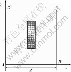
Fig.1 Simulation model for heat transfer of MMCs during solidification processing
2.1 Geometrical conditions
As shown in Fig.1, the shadowed part represents the reinforcement and the vacancy part represents the matrix. The letter R and m are the subscript of reinforcement parameters and matrix parameters, respectively.
2.2 Physical conditions
According to the energy conservation, we can get the following heat transfer equation in the matrix region (��m) ignoring the density variation during the phase change:
![]()
��m=Km/(��mcm) (1)
where Km , ��m and cm are thermal conductivity, density and specific heat of the matrix, respectively; t is the solidification time; x, y and Tm are the coordinate parameters and the matrix temperature, respectively. Here, we use the effective specific heat method, namely cm<>eff, where ceff is the effective specific heat (when Tm<>s, cm=ceff=cms; Ts��Tm��Tl, cm=ceff=cms+L/(Ts-Tl); Tl<>m, cm=ceff=cml. cms and cml are special heat of the solid and liquid matrix, respectively; L is latent heat of fusion; Ts and Tl are the solidus and liquidus temperature of the matrix, respectively).
Similar to the matrix, in the reinforcement region (��R), the heat transfer equation is
![]()
��R=KR/(��RcR) (2)
where KR and cR are thermal conductivity, density and specific heat of the reinforcement, respectively; TR is the reinforcement temperature.
2.3 Boundary conditions
At the interface between the reinforcement and matrix:
Tm=TR (3)
On the adiabatic boundary of AB, BC and AD:
![]() (4)
(4)
On the cold boundary of DC:
T=T0 (5)
where T0 is the cold end temperature.
2.4 Initial conditions
In the whole region:
��=��m+��R (6)
When t=0, T=Tm
where Tm is the initial temperature.
3 Finite element model
The matrix adopts the planar linear three-node triangle element and the reinforcement adopts the planar four-node quadrangle element. The size of the element is in the range of 0.5-3 ?m and time step is in the range of 1.2��10-9-1��10-7 s. The physical properties of the matrix and reinforcement and the pertinent data for calculation are shown in Table 1. The factors influencing the temperature field (Lc) are classified in four groups. Those are the size of the unit, cold boundary temperature, properties of the reinforcement and the different materials of the reinforcement, respectively. The calculation cases are: 1) The metal matrix is industrial pure aluminum, the reinforcement is alumina short fiber, the initial temperature is 750 �� and the cold boundary temperature is 0 ��; 2) When the metal matrix is industrial pure aluminum, the reinforcement is alumina short fiber, the initial temperature is 750 �� and the distance (l) between cold boundary and reinforcement is 100 ?m, the boundary cold temperatures are 0, 23, 100, 200, 300, 400, 500 ��, respectively; 3) The metal matrix is industrial pure aluminum, the l is 100 ��m, the cold boundary temperature is 0 �� and the initial temperature is 750 ��; 4) When the metal matrix is industrial pure aluminum, the l is 100 ?m, the cold boundary temperature is 0 �� and the initial temperature is 750 ��, the reinforcement materials are Al2O3, SiC, C, B, Ta and W, respectively.
Table 1 Physical parameters of different kinds of reinforcements
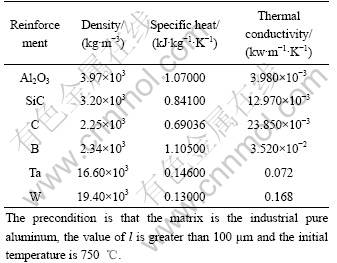
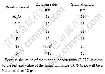
Table 2 Predicted and measured Lc of different kinds of reinforcements
4 Results and discussion
During the solidification, the liquid-solid interface is initially planar (as shown in Fig.2(a)), and the heat input from the liquid to the interface is equal to the heat output from the interface to the solid. However, when the interface approaches the bottom of the reinforcement, the temperature field of the liquid in the vicinity of the liquid-solid interface is disturbed by the nearby reinforcement and the heat transport balance of the interface is broken, and finally, the solid-liquid interface becomes curved (as shown in Fig.2(b) and (c)). If the heat inputting from the liquid to the interface is greater than the heat outputting from the interface to the solid, the liquid-solid interface will be concave (as shown in Fig.2(c)). Otherwise, it will be convex (as shown in Fig.2(b)). For the pure metal matrix, the change of the liquid-solid interface shape indicates the reinforcement influence on the temperature field during solidification. In addition, the change of abrupt reinforcement influence on the temperature field can be considered local. Now, we use the term Lc to describe the size of this local influential zone.
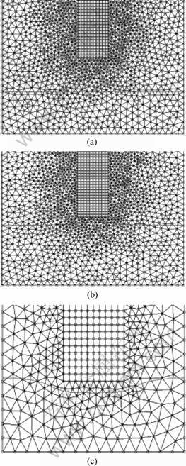
Fig.2 Morphologies of solid-liquid interface during direct solidification: (a) Planar interface; (b) Convex interface; (c) Concave interface
For convenience, some important parameters will be introduced first. Referring to Fig.3, l represents the distance from the bottom of reinforcement to the cold end. The point Wp on the planar part of the liquid-solid interface lies between AD and EH. The point Wc on the curve part of the solid-liquid interface lies at the centerline of AD and BC. The distance from Wc and Wp to the cold end represents the position of different parts of solid-liquid interface. Their ratios will be calculated (as shown in Fig.4). The ratio value greater than 1 means that the liquid-solid interface is convex and the value less than 1 means concave interface. Just at the moment, when the moving liquid-solid interface is suddenly curved, the distance from the interface to the bottom side of the reinforcement is the value of Lc.
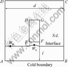
Fig.3 Schematic diagram of directional solidification of unit
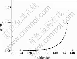
Fig.4 Curve of ratio vs position of solid-liquid interface
From Fig.5, we can see that under the same l, the change of the position of the point Wp or Wc does not depend on the width of the unit, d. Thus, the width of the unit does not affect the movement of the liquid-solid interface and the value of Lc.
The value of the Lc under the different l is shown in Fig.6, from which we can find that when the value of the l is less than 75 ?m, Lc changes linearly with the l. But when the value of the l is greater than 75 ?m, Lc will be constant.
The value of Lc under the different cold boundary temperatures is shown in Fig.7. We can see that the cold bottom temperature does not influence Lc, which confirms the fact that the reinforcement influence on the solidification is really local. When the value l is greater than a critical value, Lc is invariable with the increase of l, which also proves that the reinforcement influence on the solidification is local if the interstice size is not too small.
From Fig.8, we can find that, regarding the reinforcement with the density of 3.97��103 kg/m3, specific heat of 1.071 1 kJ��kg-1��K-1 and thermal condu- ctivity of 3.975��10-3 kW��m-1��K-1, the result of the density value increasing of one, two, three and four magnitude is the same with the result of the specific heat value increasing of one, two, three and four magnitude, respectively, without the change of other two parameters. So, the change of the density is equivalent to the change of the specific heat in influencing Lc.
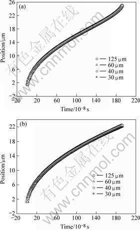
Fig. 5 Curves of point Wc and Wp vs time (l=25 ?m): (a) Wc; (b) Wp
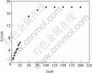
Fig. 6 Relationship between Lc and l
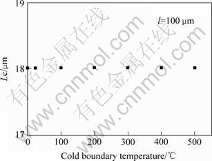
Fig. 7 Relationship between Lc and cold boundary temperature
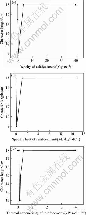
Fig.8 Curves of Lc vs parameters of reinforcement
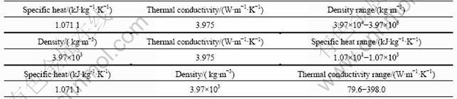
In the relationship between Lc and the parameters of the reinforcement, there is a transition region, which is v shape in Fig. 8.The range of the transition region for every parameter of the reinforcement is shown in Table 3. Except in the transition range where Lc is less than 18 ?m and Lc remains constant 18 ?m in other range, which is either on the left side of the transition region or on the right side, as shown in Fig.8.Through the above analysis of the relationship between Lc and the parameter of the reinforcement, we can get an experiential rule: the precondition is that the matrix is industrial pure aluminum, l is greater than 100 ?m and the initial temperature is 750 ��. The rule is as follows. 1) If the values of three parameters of the reinforcement (density, specific heat and the thermal conductivity) are less than the left end value of the transition region Lc will be 18 ?m. 2) If the values of the three parameters of the reinforcement are greater than the right end value of the transition region, Lc will be 18 ?m. 3) In the above two cases (1) or (2), if the value of one of three parameters is too close to the end value of the transition region, the value of Lc may be a little less than 18 ?m. 4) If one of the three parameters is in the range of the transition region, Lc will be less than 18 ?m.
If we know the three parameters of the reinforcement using the above experiential rule, we can predict Lc. The results are shown in Table 2. 1) The three parameters of the reinforcement Al2O3, SiC, C(carbon), B��boron��obey the rule 1. The values of density, specific, and the thermal conductivity are less than the left end value of the transition range, respectively. So, the predicted Lc is 18 ?m which is consistent with the measured value 18 ?m. 2) The parameter value of the reinforcement, Ta, obeys the rule 1 and 3. That is the parameter value is less than the left end value of the transition range, but the thermal conductivity value is close to the left end value. So, the predicted Lc will be a little less than 18 ?m, which is consistent with the measured value 17 ?m. 3) The parameter value of the reinforcement, W, obeys the rule 4. That is the thermal conductivity is in the range of the transition region. So, Lc will be less than 18 ?m, which is consistent with the measured value 12 ?m.
Table 3 Range of thermophysical properties of reinforcement transition region for each parameter of reinforcement
5 Conclusions
1) Simulation shows that the width of the unit will not change the movement of the liquid-solid interface and Lc value. If the l value is small (<75 ?m), Lc will change linearly with the change of l value, otherwise if the l value is large (>75 ?m), the value of the Lc will be invariant.
2) The cold end temperature does not affect Lc. The change of the density of the reinforcement is equivalent to the change of the specific heat in influencing the Lc value.
3) There is a transition range between Lc and physical parameters of the reinforcement. In the transition range, Lc is less than 18 ?m, otherwise, Lc is not less than 18 ?m.
References
[1] ZHANG Di, GENG Ke, QIN Ye-xia, LU Wei-jie, JI Bo. The orientation relationship between TiB and RE2O3 in situ synthesized titanium matrix composites[J]. Journal of Alloys and Compounds, 2005, 392: 282-284.
[2] YOUSSEF Y M, DASHWOOD R J, LEE P D. Effect of clustering on particle pushing and solidification behaviour in TiB2 reinforced aluminium PMMCs[J]. Composites, 2005, 36A:747-763.
[3] MORTENSEN A, GUNGOR M N, CORNIE J A, FLEMINGS M C. Alloy microstructures in cast metal matrix composites[J]. Journal of Metals, 1986, 38: 30-35.
[4] MORTENSEN A, CORNIE J A, FLEMINGS M C. Columnar dendritic solidification in a metal-matrix composites[J]. Metallurgical Transactions, 1988, 9A: 709-721.
[5] LI Q F, MCCARTNEY D G, WALKER A M. Development of solidification microstructures in a fibre reinforced alloy[J]. Journal of Materials Science, 1991, 26: 3565-3574.
[6] HU H. Grain microstructure evolution of Mg(AM50A)/SiCp metal matrix composites[J]. Scripta Materialia, 1998, l39(8): 1015-1022.
[7] LUO A. Development of matrix grain structure during the solidification of a Mg(AZ91)/SiCp composite[J]. Scripta Metallurica et Materialia, 1994, 31(9): 1253-1258.
[8] DAS S, PRASAD S V, RAMACHANDRAN T R, ROHATGI P K. Microstructures of cast AL-Si alloys in the presence of dispersed graphite particles[J]. Materials Transactions, 1991, 32(2): 189-194.
[9] ASTHANA R, DAS S, DAN T K, ROHATGI P K. Solidification of aluminium-silicon alloy in the presence of graphite particles[J]. Journal of Materials Science Letters, 1986, 5(11): 1083-1086.
[10] ROHATGI P K, PASCIAK K, NARENDRANATH C S. Evolution of microstructure and local thermal conditions during directional solidification of A356-SiC particle composites[J]. Journal of Materials Science, 1994, 29:5357-5366.
[11] NAGARAJAN S, DUTTA B, SURAPPA M K. The effect of sic particles on the size and morphology of eutectic silicon in cast A356/SiCp composites[J]. Composites Science and Technology, 1999, 59: 897-902.
[12] CAI Y, TAN M J, SHEN G J, SU H O. Microstructure and heterogeneous nucleation phenomena in cast SiC particles reinforced magnesium composite[J]. Materials Science and Engineering, 2000, A282: 232-239.
[13] MORTENSEN A, FLEMINGS M C. Solidification of binary hypoeutectic alloy matrix composite casting[J]. Metallurgical and Materials Transactions A, 1996, A27: 595-607.
[14] MORTENSON A. Steady state solidification of reinforced binary alloys[J]. Materials Science and Engineering, 1993, A173: 205-212.
[15] SEKHAR J A, TRIVEDI R. Solidification microstructure evolution in the presence of inert particles[J]. Materials Science and Engineering, 1991, A17: 9-21.
[16] SEKHAR J A, TRIVEDT R. Development of solidification microstructures in the presence of fibers or channels of finite width[J]. Materials Science and Engineering, 1989, A114: 133-146.
[17] HADJI L. Morphological instability prior to particle engulfment by a solidifying interface[J]. Scripta Materials, 2003, 48: 665-669.
[18] YANG Y, GARVIN J W, UDAYKUMAR H S. Sharp interface simulation of interaction of a growing dendrite with a stationary solid particle[J]. International Journal of Heat and Mass Transfer, 2005, 48: 5270-5283.
[19] FABIETTI L M, SEKHAR J A. Quantitative microstructure maps for restrained directional growth[J]. Journal of Materials Science, 1994, 29: 473-477.
[20] KANG C G, RAY S, ROHATGI P K. A micromechanical solidification heat transfer in one dimensional Al-Al2O3 composite and its consequence on microstructure evolution[J]. Material Science and Engineering, 1994, A188: 193-199.
[21] SEO Y H, KANG C G. Micromechanical solidification heat transfer and initial strain estimation in the fabrication process of particles-reinforced aluminum composites[J]. Journal of Materials Processing Technology, 1997, 72: 152-161.
[22] HO S, SAIGAL A. Solidification of SiC/Al fiber-reinforced metal matrix composites[J]. Scripta Metallurgica et Materialia, 1994, 31(3): 351-356.
[23] MOUSSA B, SIMPSON J E, GARIMELLA S V. Concentration fields in the solidification processing of metal matrix composites[J]. International Journal of Heat and Mass Transfer, 2002, 45: 4251-4266.
[24] FLEMINGS M C. Solidificating Processing[M]. New York: McGraw-Hill, 1974.
[25] KURZ W, FISHER D J. Fundamentals of Solidification[M]. Aedermannsdorf: Trans Tech Publication, 1989.
[26] ROHATGI P, ASTHANA R. The solidification of metal-matrix particulate composites[J]. J Met, 1991, 43: 35-41.
(Edited by LI Yan-hong)
Corresponding author: WANG De-zun; Tel: +86-451-86414816; E-mail: wangdz@hit.edu.cn
