
J. Cent. South Univ. Technol. (2008) 15: 15-19
DOI: 10.1007/s11771-008-0004-0
![]()
Synthesis of carbon nanofibers by ethanol catalytic combustion technique
LI Fei(�� ��), ZOU Xiao-ping(��Сƽ), CHENG Jin(�� ��), ZHANG Hong-dan(�ź쵤),
REN Peng-fei(������), WANG Mao-fa(���), ZHU Guang(�� ��)
(Research Center for Sensor Technology, Beijing Information Technology Institute, Beijing 100101, China)
Abstract:
A general, simple and economic synthetic method for synthesizing carbon nanofibers was presented. In the method, ethanol was employed as carbon source; metal salts such as nickel nitrate, ferric nitrate and ferric chloride were used as catalyst precursor respectively; copper plate was employed as the support material. A lot of products were obtained by catalytic combustion deposition of ethanol vapor. Then the as-prepared carbon nanofibers were characterized by field-emission scanning electron microscopy, transmission electron microscopy, Raman spectroscopy, energy dispersion X-ray spectroscopy and selected-area electron diffractometry. By analyzing the results of characterization, the conclusions are as follows: 1) the large catalyst particles tend to form large-diameter CNFs, small catalyst particles are inclinable to form small-diameter CNFs; 2) the morphology of the catalyst can affect the final morphology of the CNFs. Moreover, the possible growth mechanisms were proposed and the degree of graphitization of samples was estimated by Raman spectroscopy characterization.
Key words:
1 Introduction
In recent years, carbon nanofibers (CNFs) have become a promising research direction. It is considered to have widely potential applications for their remarkable properties that are similar to those of carbon nanotubes, such as high elastic modulus, strong strain, and high conductivity. Syntheses of CNFs have been investigated for a wide range of applications today because CNFs of different morphologies are required. So many synthetic approaches have been developed for synthesizing carbon nanofibers, for instance, electric arc discharge, plasma enhanced chemical vapor deposition (PECVD)[1] and chemical vapor deposition (CVD)[2]. However, current synthetic methods suffer from high cost, complex experimental setup, etc.
CNFs (also known as carbon filaments) can be grown from the catalytic decomposition of certain hydrocarbons over small catalyst particles such as iron, cobalt, nickel, some metal alloys and metal oxide. The diameter of the nanostructure is generally controlled by the size of the catalyst particle.
In this work, an alternative way was developed to synthesize carbon nanofibres by ethanol catalytic combustion (ECC) technique by using pure ethanol as the fuel, metal salt as the catalyst precursor and copper as the substrate material.
2 Experimental
CNFs were formed by ECC over catalyst derived from the catalyst precursors (ferric nitrate or nickel nitrate or ferric chloride)supported on substrate. The remarkable feature of the synthetic method is the use of the very common laboratory ethanol burners.
The experiments were performed in air under atmospheric pressure. The first step was to prepare the catalyst particles that approximately determined the final diameter of the CNFs. Here, the wet chemical method was used, that is, a liquid solution containing catalyst precursor in the form of metal salts such as ferric nitrate or nickel nitrate or ferric chloride was dropped to the substrate. Some quantities of metal salt were dissolved in the pure ethanol. And then the prepared solution was sonicated for tens of minutes to form a suspension of catalyst precursor, which provided small catalyst precursor particles. One drop of the saturated catalyst precursor solution was dropped with a dip-pen to the copper support material, which was then placed in an inner flame for several minutes without introducing any other gases for the CNFs growth. After a desired time, wool-like products accumulated on the copper plate.
The carbon deposits were collected from the substrate. And then the samples were examined by a JEOL 6500F scanning electron microscope (SEM), which was used to observe the morphology of the CNFs.
For transmission electron microscopy (TEM) observations, the samples were prepared by sonicating in pure ethanol for several minutes, followed by deposition of a few drops of the resulting suspension on the TEM copper grid. TEM with a JEOL 2010 microscope was employed to characterize the structure of the CNFs. Raman spectroscopy was used to characterize the degree of graphitization of the CNFs.
3 Results and discussion
3.1 Catalytic effects
It is well-known that the size of the CNF formed is directly related to that of the catalyst particles[3]. Fig.1 shows TEM images of CNFs synthesized by using nickel nitrate, ferric nitrate and ferric chloride as the catalyst precursors, respectively. By careful observation of the images, it is found that the size of the catalyst nanoparticles approximately determines the final diameter of the carbon nanofibers. The large catalyst particles tend to form CNFs with large diameter and the small catalyst particles usually result in the CNFs with small diameter. This is in good agreement with KIM et al��s observation[4]. Therefore, it is necessary to control this parameter. The dried catalyst powders are not suitable for ECC technique because the dried catalyst precursor particles can easily move and easily fall from the support during growth. For the above reasons, the wet chemical method was adopted, a few drop of the catalyst precursor solution was dipped onto the substrate with a dip pen. In the initial process of the synthesis, the catalyst precursor is decomposed into metal oxide by combustion. The metal oxide is very easy to be reduced into metal at high temperature in the reducing environment, even carbide. These metals, metal oxides or carbide play an important catalytic role in the formation of CNFs, which can catalyze the subsequent growth of CNFs.
Fig.2(a) shows the morphology of the wool-like glomerations. These agglomerations may be the results as follows: firstly, the strong cohesive forces of the catalyst particles can result in this case; secondly, the random flowing gas of air can result in the flame perturbations that drive the catalyst particles to move on the substrate, and then the metal catalyst particles or metal oxide catalyst particles are driven to coalesce into large particles. Due to the high movement and reactivity of the catalyst particles, the catalyst nanoparticles are often in the shape of catalyst agglomerations that can form carbon nanofiber clusters (as shown in Fig.2(b)).
The morphology of the catalyst nanoparticle approximately determines the final morphology of the CNFs. Fig.2(c) shows a TEM image of a pear-shaped substance inside CNF formed by using ferric chloride as catalyst precursor. From Fig.2(c) it can be seen that there is a pear-shaped substance containing catalyst encapsulated in the CNF, which promotes the growth of CNF. The diameter of the particles at position where the black arrow points at is more than 70 nm. It can be inferred that this growth mode is a catalytic process involving the surface diffusion of carbon atom catalyst particles. The carbon atoms diffuse over the catalyst surface to form a pear-like structure that emanates from the circumference of the catalyst. This provides a synthetic route to produce magnetically functionalized CNFs. The filled CNFs may find a lot of applications ranging from the implementation of individual filled fibers in sensors for magnetic scanning probe microscopy to the assembly of aligned high density magnetic nanocores for future magnetic data storage devices. Moreover, the carbon shell provides an effective protection against oxidation. The exceptional mechanical properties and light mass of CNFs make them potential filling materials in polymer composites. CNFs can improve the strength and stiffness of a polymer, as well as add multifunctionality (such as electrical conductivity) to polymer based composite systems[1].
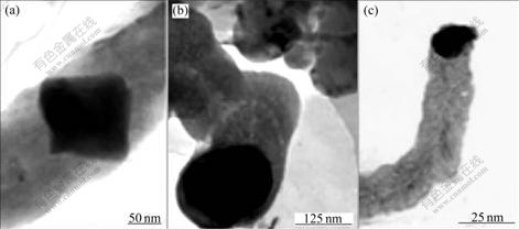
Fig.1 TEM images of samples produced by using nickel nitrate(a), ferric nitrate(b) and ferric chloride(c) as catalyst precursor
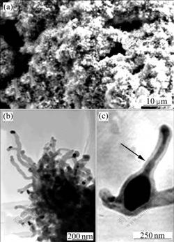
Fig.2 Microstructures of CNFs: (a) SEM image of large wool-like agglomerations using ferric chloride as catalyst precursor; (b) TEM image of carbon nanofiber cluster using ferric nitrate as catalyst precursor; (c) TEM image of pear-shaped substance inside CNF using ferric chloride as catalyst precursor
3.2 Growth mechanism
Fig.3(a) shows a CNF with a catalyst particle encapsulated in a CNF. There are two possible growth modes that may explain this phenomenon. The most commonly accepted mechanism is the catalytic decomposition of the carbon feedstock and bulk diffusion of carbon[1]. According to this growth mode, the hydrocarbon gas decomposes on the front-exposed surfaces of catalyst particles to release hydrogen and carbon, which dissolve on the particles. The dissolved carbon diffuses through the catalyst particles and through
the catalyst particles and precipitates at the end to form the body of the carbon fiber. Due to the exothermic decomposition of hydrocarbons, it is believed that a temperature gradient exists across the catalyst particle. Since the solubility of carbon in a catalyst particle is temperature dependent, precipitation of excess carbon will occur in the colder zone behind the particle, thus allowing CNF to grow with approximate diameter as the width of the catalyst particle. Instead of the diffusion of carbon atoms, the other growth mode is a catalytic process involving the surface diffusion of carbon atoms around the catalyst particles[2]. That is, the carbon atoms diffuse over the catalyst surface to form a pole-like structure that emanates from the circumference of the catalyst.
Fig.3(b) exhibits a CNF with a catalyst particle in the center. The growth mechanism of Fig.3(b) is obviously different from the above growth mechanism of CNFs. It is speculated that the CNF grows on both side of the catalyst at the same time, which is referred as the bidirectional growth mode[5].
Fig.3(c) shows a CNF with a catalyst particle attached to one end. Observation from the TEM reveals that certain faces of iron-containing catalyst possess the ability to precipitate dissolved carbon in the form of graphite platelets. The phenomenon is possibly illustrated by the tip growth mechanism[6] and the stack mechanism[3] of graphene layers. In Fig.3(c), there is a single face of the particle involved in the interaction with the hydrocarbon reactant molecule. The graphite platelets only form from the crystallographic faces of the catalyst particle, and the catalyst stays at the growing end of the CNFs, which has been explained by tip growth mechanism[7]. The growth process of the CNFs may be explained by the stack mechanism, that is, graphene layers repeatedly deposit on certain crystallographic face of the catalyst particle. This process involves the feedstock diffusion on or through the catalyst particle.
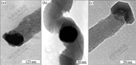
Fig.3 TEM images of CNFs using ferric chloride(a), nickel nitrate(b) and ferric nitrate(c) as catalyst precursor
Even though carbon diffusion through the catalyst particle has been shown to be the rate-determining step[4], a further aspect should be taken into consideration in the manner by which the hydrocarbons are bond and ultimately react with the catalyst surface. Prior to diffusion, a crucial event should be realized to make the growth process continue, namely, the adsorption and decomposition of the reactant gas[8]. The catalyst particle adsorbs hydrocarbon on certain face, then the hydrocarbon is decomposed on the catalyst particles surface, and subsequent newly arriving carbon continues to overcoat the old one, and these events are repeated until the catalyst is no longer able to catalyze the growth of CNFs on account of the formation of graphitic overlayers, which are interfered with the further growth of CNFs.
3.3 Nanostructure and microstructure
The diameter of the most visual CNFs synthesized is basically consistent from the base to the tip. The growth of a CNF is influenced by many factors, including the catalytic decomposition of a carbon source, the activity of the catalyst and the conditions of the growth. So, the CNFs can adopt various shapes such as straight, curved and helix. Fig.4(a) shows a photograph of a segment of a straight CNF. The long straight CNF is synthesized by Fe-catalyzed decomposition of ethanol. The length from arrow 1 to arrow 2 is more than 20 ��m. The CNF structure will likely be straight as long as the precipitation of carbon on the surface of nanoparticle is performed with constant rate. Any perturbation in growth behavior will give rise to abnormalities in the formation of the carbon fibers and will result in the generation of other structure forms, such as coiled configuration (Fig.4(b)). It seems that the same catalyst precursor can form different structural CNFs.
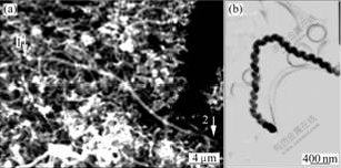
Fig.4 Microstructures of straight and helix-shaped CNFs: (a) SEM image of straight CNF; (b) TEM image of helix- shaped CNF
Fig.5 shows a segment of a CNF consisting of cylindrical graphene sheets with a coarse surface. It is speculated that the CNF with large surface area has potential applications for gas storage, absorbents and supercapacitors[9] and it is assumed that the substance marked by a black arrow is amorphous carbon.
Selected area electron diffractometry(SAED) is an excellent technique to study the microstructure of the CNFs[10]. The SAED graph(Fig.6) exhibits a ring pattern, which indicates that the CNF is polycrystalline material.
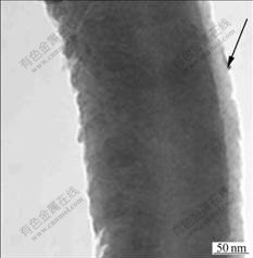
Fig.5 TEM image of product carbon nanofiber with coarse surface
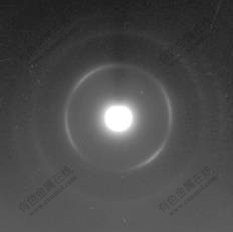
Fig.6 Selected area electron diffraction pattern of CNFs using ferric nitrate as catalyst precursor
3.4 Raman spectrum analysis
Raman spectroscopy is a simple and good tool for analyzing the structure of the CNFs[11]. Raman spectra of CNFs were excited by a laser with wavelength of 514.5 nm at room temperature. Tow peaks (1 346.9 and 1 577.6 cm-1 in Fig.7(a); 1 346.9 and 1 592.0 cm-1 in Fig.7(b); 1 345.5 and 1 587.7 cm-1 in Fig.7(c)) can be observed in the range of 1 200-1 700 cm-1 in a typical Raman spectrum. It is believed that 1 250-1 450 cm-1 is the disorder-induced phonon mode (D-band), which arises from the disordered components[12]; 1 550-1 600 cm-1 is the graphite band (G-band)[13], which is produced from the high degree of symmetry and order of carbon materials, and generally used to identify well-ordered CNFs. In Figs.7(a) and (b), peaks D are all higher than peaks G, while peak D is lower than peak G in Fig.7(c), which indicates that the sample using ferric chloride as the catalyst precursor has relatively larger size graphite clusters[14] within the CNF among the three samples. According to the results in Ref.[15], the amount of disordered carbon can be estimated using a fractional value f (f=ID/(ID+IG)). The values of f by using nickel nitrate, ferric nitrate and ferric chloride as the catalyst precursor are 52.46%, 53.75% and 47.08%, respectively. It can be seen that the amount of amorphous carbon is the smallest for the sample synthesized by the interaction of ethanol with ferric chloride precursor.
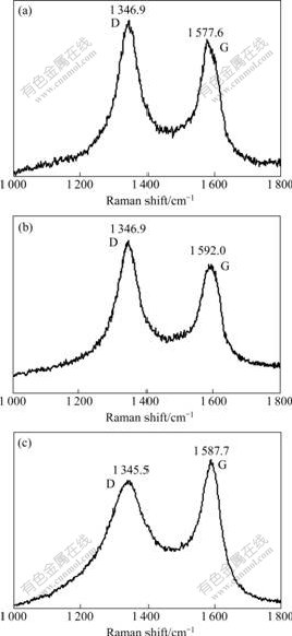
Fig.7 Raman spectra of typical sample using different metal salts ferric chloride as catalyst precursors: (a) Nickel nitrate; (b) Ferric nitrate; (c) Ferric chloride
4 Conclusions
1) Liquid ethanol can be used as an alternative kind of carbon source for CNFs preparation. The potential advantages of this technique are low synthetic temperature and simple setup.
2) CNFs growth by the ECC technique requires catalyst particles such as Fe, Co, Ni or their oxides, a carbon feedstock and heat. The diameter of the fibers produced is closely related to the physical dimension of catalyst particle. And through Raman characterization on samples, the sample using ferric chloride as the catalyst precursor has higher degree of graphitization than that using other catalyst precursors.
3) The formation of CNFs is related to a combination of factors including the morphology of catalyst, catalyst activity, and the diffusion of carbon through/on the catalyst particles. The synthesis of CNFs is a widely debated issue, and further research will be performed in this area, such as the treatment of substrate, the controllability of the CNF growth and the preparation of nanoscale catalyst particles.
References
[1] TEO K B K, SINGH C, CHHOWALLA M, MILNE W I. Catalytic synthesis of carbon nanotubes and nanofibers[M]. California: American Scientific Publishers, 2003: 1-22.
[2] CHAMBERS A, RODRIGUEZ N M, BAKER R T K. Influence of copper on the structural characteristics of carbon nanofibers produced from the cobalt-catalyzed decomposition of ethylene[J]. J Mater Res, 1996, 11(2): 430-438.
[3] RODRIGUEZ N M, CHAMBERS A, BAKER R T K. Catalytic engineering of carbon nanostructures[J]. Langmuir, 1995, 11(10): 3862-3866.
[4] KIM M S, RODRIGUEZ N M, BAKER R T. The interaction of hydrocarbons with copper-nickel and nickel in the formation of carbon filament[J]. Journal of Catalysts, 1991, 131(1): 60-73.
[5] BAKER R T K. Catalytic growth of carbon filaments[J]. Carbon, 1989, 27(3): 315-323.
[6] HEYNING O T, BERNIER P, GLERUP M. A low cost method for the direct synthesis of highly Y-branched nanotubes[J]. Chem Phys Lett, 2005, 409(1): 43-47.
[7] AJAYAN P M. How does a nanofiber grow[J]. Nature, 2004, 427(29): 402-403.
[8] RODRIGUEZ N M. A review of catalytically grown carbon nanofibers[J]. J Mater Res, 1993, 8(12): 3233-3250.
[9] ZHAO J C, LAI C Y, DAI Y, XIE J Y. Synthesis of mesoporous carbon as electrode material for supercapacitor by modified template method[J]. J Cent South Univ Technol, 2005, 12(6): 647-652.
[10] BAKER R T K, PRESTRIDGE E B, GARTEN R T. Elelctron microscopy of supported metal particles: I. Behavior of Pt on titanium oxide, aluminum oxide, silicon oxide, and carbon[J]. Journal of Catalysis, 1979, 56(3): 390-406.
[11] WANG Y, SERRANO S, SANTIAGO-AVIL?S J J. Raman characterization of carbon nanofibers prepared[J]. Synthetic Metals, 2003, 138(3): 423-427.
[12] DRESSELHAUS M S, EKLUND P C. Phonons in carbon nanotubes phonons in carbon nanotubes[J]. Advances in Physics, 2000, 49(6): 705-814.
[13] JORIO A, SOUZA FILHO A G, DRESSELHAUS G, DRESSELHAUS M S, SWAN A K, UNLU M S, GOLDBERG B B, PIMENTA M A, HAFNER J H, LIEBER C M, SAITO R. G-band resonant Raman study of 62 isolated single-wall carbon nanotubes[J]. Phys Rev B, 2002, 65(155): 412.
[14] BOSKOVIC B O, STOLOJAN V, ZEZE D A, FORREST R D, SILVA S R P. Branched carbon nanofibers network synthesis at room temperature using radio frequency supported microwave plasmas[J]. J Appl Phys, 2004, 96(6): 3443-3446.
[15] KISHORE N, SACHAN S, RAI K N, KUMAR A. Synthesis and characterization of a nanofiltration carbon membrane derived from phenol-formaldehyde resin[J]. Carbon, 2003, 41(15): 2961-2972.
Foundation item: Project(66167044) supported by the Academic Human Resources Development in Institutions of Higher Learning under the Jurisdiction of Beijing, China; Project(66062021) supported by the Science and Technology Activity for Chinese Homecoming Fellow Abroad, Program of Beijing Key Laboratory for Sensor
Received date: 2007-04-28; Accepted date: 2007-06-12
Corresponding author: ZOU Xiao-ping, PhD; Tel: +86-10-64884673-816; Fax: +86-10-64879486; E-mail: xpzou2005@gmail.com
