
J. Cent. South Univ. (2012) 19: 174-178
DOI: 10.1007/s11771-012-0988-3![]()
Multi-stage optimum design of magazine type automatic tool changer arm
KIM Jae-Hyun, LEE Choon-Man
School of Mechatronics, Changwon National University, Changwon 641-773, Korea
? Central South University Press and Springer-Verlag Berlin Heidelberg 2012
Abstract:
To enhance machining efficiency, tool change time has to be reduced. Thus, for an automatic tool changer attached to a machining center, the tool change time is to be reduced. Also the automatic tool changer is a main part of the machining center as a driving source. The static attributes of the automatic tool changer using the commercial code, ANSYS Workbench V12, were tried to interpret. And the optimum design of automatic tool changer arm was proposed by performing the multi-stage optimum design. The shape optimization of the automatic tool changer was proposed and the result was verified to obtain acceptable improvements. It is possible to obtain an optimized model in which the maximum deformation, maximum stress, and mass are reduced by 10.46%, 12.89% and 9.26%, respectively, compared with those of the initial model. Also, the results between conventional method by the design of experiments and proposed method by the multi-stage optimum design method were compared.
Key words:
automatic tool changer; optimum design; structural analysis; exchange arm��
1 Introduction
Recently, in machine manufacturing industries, molds and machine parts have been changed to small quantity batch production system. Also, improvements in productivity and cutting rate are required. Whereas, it is true that high quality and low cost are to be targeted from a practical standpoint. Therefore, the machine tools for such aims pursue to achieve high-speed processing, implement automation, and reduced lead time. As a result, it is possible to check the states of tools and workpieces using proper sensors in the machine tools. In addition, a machining center based on an automatic tool changer (ATC) and an automatic pallet changer (APC) aims to operate an unattended operation factory for 24 h. The automatic tool changer stores the tools used in a machining center to its magazine and changes the tools automatically as required. The tool changed by such ATC is precisely equipped to a spindle [1].
Also, it represents an advantage that an operator of the machining center is able to engage in other works due to the less interference for the machine tools. That is to say, the operator can control other machine tools or prepare the next workpieces, which leads to reduced production time.
The magazine type ATC used in this study represents a feature that many tools are stored in the magazine. In the change of tools, two arms move to change the equipped tool to the next tool by rotating them by 180�� in a directly changed manner [2]. Thus, it is necessary to ensure the technologies for both the structural characteristics of arms and the design of lightweight simultaneously.
In actual industrial fields, design optimization is very important. Therefore, various optimization methods are presented for the optimization of various mechanical parts [3].
SONG et al [4] presented optimization design of the short journal bearing by using enhanced artificial life optimization algorithm. ALLAIRE et al [5] combined the topological and shape derivations on the structural optimization. BAGCI and AYKUT [6] presented Taguchi optimization to verify the optimum surface roughness of the CNC milling. LAMBERTI [7] presented a design optimization algorithm based on simulated annealing for truss structures. SEKULSKI [8] presented that the genetic algorithm can be an efficient multi-objective optimization tool for simultaneous design of the topology and sizing of ship structures.
SEO et al [9] presented shape optimization and its extension to topological design based on isogeometric analysis.
In optimizing the ATC arm, the factors of the structural characteristics and the lightweight are contrary to each other [10]. It shows a trade-off that if it pursues to improve the lightweight in structures, the structural characteristics will represent a weakness, and if the structural characteristics are improved, the achievement of the lightweight is difficult. Therefore, for satisfying these contrary factors and optimizing them, the optimization of such arm shapes in different way is presented by using the design of experiments [11].
In this study, for achieving a more improved optimization model than the previous study [11], a multi-stage optimum design was performed. The optimum design was presented using the commercial analysis programs, CATIA V5 and ANSYS Workbench, and the analytic validity was investigated through comparing the initial and conventional optimized models with the optimized model implemented in this study.
2 Structure of ATC
ATC consists of three elements, such as magazine part, changer part, and arm part. The magazine part is a device that stores many tools and changes tools using servo motors. The changer part is equipped with servo motors, which rotate arms. The arm part shows an arm shape and changes tools by gearing the tools in the spindle and magazine in a machining center by rotating them by 180��.
Figure 1 illustrates the entire structure of the ATC modelled by using the CATIA V5 R17.
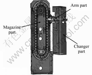
Fig. 1 Structure of magazine type ATC
The structural analysis of the initial model of the arm was performed. Regarding the reference of the performed finite element analysis, the finite element analysis of the initial model was carried out using the commercial analysis program, Ansys Workbench V12. The analysis was performed by minimizing the additional part employed in the arm. In the analysis method, a hex dominant method was applied in which a finite element analysis had totally 51 794 nodes and 13 496 elements. Figure 2 shows the initial finite element model of the arm.
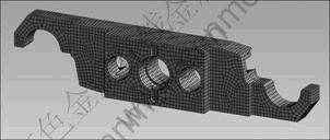
Fig. 2 Initial finite element model of arm
For the boundary conditions in the analysis, the hole at the center of the ATC arm was supported, and the gravitational acceleration was applied to the entire body. In the load conditions, a load of 147 N was applied to the clamps at both ends for considering the maximum weight of the tools.
The results of the structural analysis are presented in Fig. 3. The maximum deformation of the initial model at the clamps is 5.748 7 ��m and occurs at both ends. Also, the maximum stress is generated at the edge of the section, which pushes the rear finger of the ATC arm, and is presented by 4.176 2 MPa.
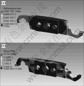
Fig. 3 Structural analysis of arm: (a) Deformation distribution; (b) Stress distribution
3 Multi-stage optimization of arm
The static compliance, fx(=D/F), can be presented by an inverse number of the static stiffness. In particular, in some machine structures like machine tools and industrial robots that require high accuracy and machining efficiency, it becomes the most important static characteristic as well as the structure weight where these factors are to be comprehensively and simultaneously evaluated. As mentioned above, the optimization of the static issue is determined as the static characteristic of these two objective functions and the minimization issue of the weight [12].
Thus, in this study, the optimization is performed as a multi-stage manner for satisfying each objective function. The first stage is configured as a stage that improves the static characteristics. By defining design factors that minimize the deformation, an optimum model can be induced. The second stage is determined as a stage for implementing its lightweight. Based on the optimum model presented in the first stage, the shape optimization is performed by aiming a reduction in its weight by 10%.
3.1 First stage of optimum design of arm
In the first stage of the optimum design, the optimum design aims to minimize the deformation of the arm.
Figure 4 illustrates the design variables of the arm.
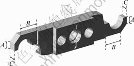
Fig. 4 Factors of ATC arm
The general formalization for the dimension and the optimum shape design can be presented by defining objective functions and limitation condition functions [13-15]. For implementing the optimum design for the ATC arm, the formalization is determined as follows:
Find X
Minimize deformation (X)
Subject to �� �� ��a
�� �� ��a
��L �� A, B, C �� ��U (��=A, B, C)
X=[A, B, C]
where X represents one of the design variables, and �� and �� show the stress and deformation, respectively. Also, ��a and ��a show the allowance values for the stress and deformation, respectively. The terms of A, B, and C are the design variables. The design variables are configured by ��30 mm in order not to present the influences of the collision and interference in structures on the design.
In the optimum design, the optimum solution can minimize the deformation of the arm using the CATIA V5 Product engineering optimizer. Table 1 gives the results of the optimization.
Figure 5 illustrates the results of the structural analysis of the optimal designed arm. The boundary conditions in the analysis are configured as the same as the existing initial model.
Table 1 Results of optimization for reducing deformation

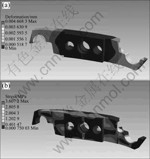
Fig. 5 Structural analysis of optimized arm for reducing deformation: (a) Deformation distribution; (b) Stress distribution
3.2 Second stage of optimum design of arm
Achieving the lightweight of the arm is an important factor for reducing the cost of workpieces. Also, it is possible to improve the economy by introducing a lightweight structure [16]. Therefore, the optimum design for implementing the lightweight of the arm is performed in the second stage. The target in reducing the mass is 10% of the arm based on the model proposed in the first stage of the optimum design. For reducing the mass of the arm, the shape optimization is carried out using the ANSYS Workbench shape optimization function. The formalization for the optimum design can be presented as follows:
Find Z
Minimize mass (Z)
Subject to �� �� ��a
�� �� ��a
��L�ܦ�r�ܦ�U
Z=[��r]
where Z is one of the design variables, �� and �� show the stress and deformation, respectively, and ��a and ��a are the allowance values for the stress and deformation, respectively. Also, the design variable, ��r, is configured to find all sections in which the mass reduction is possible except for the sections, which have some limitations in the design.
Figure 6 illustrates the results of the optimum solution that minimizes the deformation of the arm. As shown in Fig. 6, the section presented by ��Remove�� represents a mass reducible section by removing it. Based on the results, the reducible sections are removed to a maximum level. Figure 7 shows the proposed optimum shape for lightweight of the arm based on the results of the shape optimization.
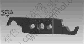
Fig. 6 Result of shape optimization using ANSYS

Fig. 7 Redesign of arm
The structural analysis is performed using the proposed optimum design. Also, the boundary conditions in the analysis are applied as the same as the existing initial model.
Figure 8 shows the results of the structural analysis, which is carried out through applying the optimum shape.
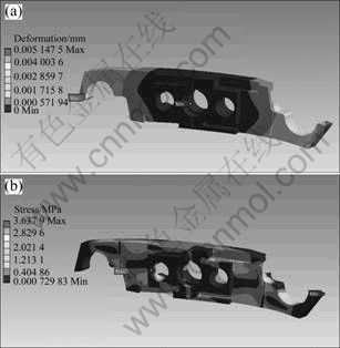
Fig. 8 Structural analysis of optimized arm for lightweight: (a) Deformation distribution; (b) Stress distribution
The maximum deformation of the model, which applies the optimal design, is reduced from 5.748 7 ��m presented in the initial model to 5.147 5 ��m by as much as 10.46% and generated at the end of the clamp as the same as the initial model. Also, the maximum stress is reduced from 4.176 2 MPa presented in the initial model to 3.637 9 MPa by as much as 12.89%. In addition, the mass is reduced from 7.871 2 kg presented in the initial model to 7.142 5 kg by as much as 9.26%.
Table 2 presents the results of the comparison of the optimum design [11] using the design of experiments performed with the multi-stage optimum design implemented in this study.
Table 2 Comparison of results
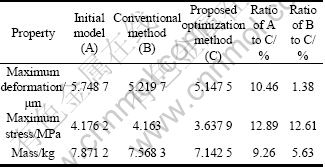
In the comparison of the results obtained in this study with the results of the design of experiments, the maximum deformation, maximum stress, and mass are reduced by 1.38%, 12.61%, and 5.63%, respectively. Thus, it can be seen that the multi-stage design using the CATIA and ANSYS performed in this study makes possible to draw more improved optimum design than the existing study.
4 Conclusions
1) By performing the multi-stage optimum design, it is possible to obtain an optimized model in which the maximum deformation, maximum stress, and mass are reduced by 10.46%, 12.89%, and 9.26%, respectively, compared with those of the initial model.
2) In the comparison of the optimum design between the multi-stage optimum design and the previously performed design of experiments, the maximum deformation, maximum stress, and mass are reduced by 1.38%, 12.61% and 5.63%, respectively.
3) By comparing the results between conventional method by the design of experiments and proposed method by the multi-stage optimum design, it is verified whether the optimum design is carried out properly.
4) Based on verification of using commercial programs of CATIA and ANSYS for multi-stage optimum design, it is expected that it can be applied to the optimum design of machine tool structures.
References
[1] LEE S W, LEE H K. Reliability evaluation of ATC for high-speed line center [J]. Journal of Korean Society for Precision Engineering, 2006, 23(6): 111-118. (in Korean)
[2] BARK T Y. The design of automatic tool changer [M]. Korea Advanced Institute of Science Univ Press, 1977: 1-11. (in Korean)
[3] ROY R, HINDUJA S, TETI R. Recent advances in engineering design optimization: Challenges and future trends [J]. CIRP Annals-Manufacturing Technology, 2008, 57: 697-715.
[4] SONG J H, YANG B S, CHOI B G, KIM H J. Optimum design of short journal bearings by enhanced artificial life optimization algorithm [J]. Tribology International, 2005, 38(4): 403-412. (in Korean)
[5] ALLAIRE G, JOUVE F, DE GOURNAY F, TOADER A. Combining topological and shape derivatives in structural optimization [C]// European Conference on Computational Mechanics. 2006: 644.
[6] BAGCI E, AYKUT S. A study of Taguchi optimization method for identifying optimum surface roughness in CNC face milling of cobalt-based alloy [J]. The International Journal of Advanced Manufacturing Technology, 2006, 29(9): 940-947.
[7] LAMBERTI L. An efficient simulated annealing algorithm for design optimization of truss structures [J]. International Journal of Computers and Structures, 2008, 86: 1936-1953.
[8] SEKULSKI Z. Multi-objective topology and size optimization of high-speed vehicle-passenger catamaran structure by genetic algorithm [J]. Marine Structures, 2009, 22: 691-711.
[9] SEO Y D, KIM H J, YOUN S K. Shape optimization and its extension to topological design based on isogeometric analysis [J]. International Journal of Solids and Structures, 2010, 47(11): 1618-1640. (in Korean)
[10] JIA S, XIN W, XIACONG J, TAEKESHI I. Multi objective optimization based fast motion detector [J]. Lecture Notes in Computer Science, 2011, 6523: 492-502.
[11] KIM J H, LEE M J, LEE C M. Geometric optimal design of an ATC arm using design of experiments [C]// Proceedings of the IASTED International Conference. 2010: 357-362. (in Korean)
[12] LEE Y W, SUNG H G. Multi-phase optimization of quill type machine structures (1) [J]. Journal of Korean Society Precision Engineering, 2001, 18(11): 155-160. (in Korean)
[13] LEE M J, LEE C M. A study on structural analysis and optimum shape design of tilting index table [J]. Journal of Korean Society Precision Engineering, 2009, 27(2): 86-93. (in Korean)
[14] ARORA J S. Introduction to optimum design, [M]. McGraw-Hill, 2003: 8-9.
[15] KIM H S, LEE Y S. Optimization design technique for reduction of sloshing by evolutionary methods [J]. Journal of Mechanical Science and Technology, 2008, 22(1): 25-33. (in Korean)
[16] KIM J S. A study on the weight-saving design of the boom in high ladder vehicle [J]. Transactions of the Korean Society of Machine Tool Engineers, 2007, 16(2): 8-13. (in Korean)
(Edited by YANG Bing)
Foundation item: Work(RTI04-01-03) supported by Grant from Regional Technology Innovation Program of the Ministry of Knowledge Economy (MKE), Korea
Received date: 2011-04-26; Accepted date: 2011-10-10
Corresponding author: LEE Choon-Man, Professor, PhD; Tel: +82-55-213-3622; E-mail: cmlee@changwon.ac.kr
Abstract: To enhance machining efficiency, tool change time has to be reduced. Thus, for an automatic tool changer attached to a machining center, the tool change time is to be reduced. Also the automatic tool changer is a main part of the machining center as a driving source. The static attributes of the automatic tool changer using the commercial code, ANSYS Workbench V12, were tried to interpret. And the optimum design of automatic tool changer arm was proposed by performing the multi-stage optimum design. The shape optimization of the automatic tool changer was proposed and the result was verified to obtain acceptable improvements. It is possible to obtain an optimized model in which the maximum deformation, maximum stress, and mass are reduced by 10.46%, 12.89% and 9.26%, respectively, compared with those of the initial model. Also, the results between conventional method by the design of experiments and proposed method by the multi-stage optimum design method were compared.
