

Effect of partial pressure of reactive gas on chromium nitride and chromium oxide deposited by arc ion plating
LI Ming-sheng(������)1, 2, FENG Chang-jie(�볤��)2, WANG Fu-hui(������)2
1. Jiangxi Key Laboratory of Surface Engineering, Jiangxi Science and
Technology Normal University, Nanchang 330013, China;
2. State Key Laboratory for Corrosion and Protection, Institute of Metal Research,
Chinese Academy of Sciences, Shenyang 110016, China
Received 10 April 2006; accepted 25 April 2006
Abstract:
The effects of reactive gas partial pressure on droplet formation, deposition rate and change of preferred orientation of CrN and Cr2O3 coatings were studied. For CrN coatings, as nitrogen partial pressure increases, the number and size of droplets increases, the deposition rate initially increases obviously and then slowly, and the preferred orientation of CrN changes from high-index plane to low-index one. For Cr2O3 coatings, with the increase of oxygen partial pressure, the number and size of droplets decreases, the deposition rate decreases and the (300) becomes the preferred orientation. These differences are ascribed to the formation of CrN (with a lower melting point) and Cr2O3 (with a higher melting point) on the surface of Cr target during the deposition of CrN and Cr2O3. Complete coatings CrN or Cr2O3 film can be formed when reactive gas partial pressure gets up to 0.1 Pa. The optimized N2 partial pressure for CrN deposition is about 0.1-0.2 Pa in order to suppress the formation of droplets and the suitable O2 partial pressure for Cr2O3 deposition is approximately 0.1 Pa for the attempt to prevent the peel of the coating.
Key words:
chromium nitride; chromium oxide; arc ion plating; reactive gas partial pressure;
1 Introduction
Arc ion plating (AIP) technique is one of the most perspective PVD methods for industrial manufacture of ceramic coatings due to the high degree of ionization in the target material, convenient control of the parameters and high deposition rate [1,2]. Owing to the thermal stability, excellent wear resistance and good corrosion resistance, chromium nitride coating [3-6] and chromium oxide coating [7,8] are regarded as the prospective alternatives in corrosion-resistance applications and in machining industry. During the process of AIP, The control of reactive gas is critical for the optimization of coating structure and improvement of coating properties. In this study, CrN and Cr2O3 coatings were respectively deposited by arc ion plating, the effects of reactive gas partial pressure on droplet formation, deposition rate and change of preferred orientation of CrN and Cr2O3 coatings were studied, and the cause was discussed.
2 Experimental
The substrate material is the wrought martensite steel 1Cr11Ni2W2MoV, which were cut into 15 mm��10 mm��2 mm and ground to 1 000 grit, followed by ultrasonic cleaning in alcohol and acetone solution.
CrN and Cr2O3 coatings were deposited on steel specimens by a homemade reactive multi-arc ion plating facility of DH-4 coating system. The target material used herein was pure Cr. Before coatings were deposited, the substrates were sputter-cleaned using Ar ion under 1 000 V DC bias voltage to remove contaminant layer and to ensure good adhesion of deposited coatings. A mass flow meter was used to adjust the N2 or O2 partial pressure from 0 to 0.8 Pa. The other deposition parameters were listed as following: substrate temperature 400 ��, total pressure 0.8 Pa, arc voltage 20 V, arc current 60 A, pulse bias voltage -450 V and duty cycle 20% and frequency 20 kHz, deposition time 30 min.
The thickness of coatings was gained by measuring the cross-section samples and the deposition rate was calculated via the coating thickness and deposition time. Surface morphologies were gained by scan electron microscopy. The phase structure was determined by X-ray diffraction using Cu K�� radiation.
3 Results and discussion
3.1 Surface morphologies
Surface morphologies of CrN and Cr2O3 deposited under different reactive gas partial pressure are shown in Figs.1 and 2. For CrN coatings, the number and size of droplets increased when N2 partial pressure increased from 0 to 0.8 Pa. While for Cr2O3, with the increase of O2 partial pressure, the number and size of droplets decreased obviously. During the process of reactive sputtering, when reactive gas pressure is high enough, a thin layer of nitride or oxide will be formed on the target surface and which is called ��target poisoning�� [9]. As shown in Fig.3 the melting point of CrN is far lower than
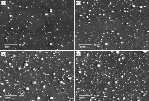
Fig.1 Surface morphologies of CrN coatings deposited at various N2 partial pressures: (a) 0.1 Pa; (b) 0.2 Pa; (c) 0.4 Pa; (d) 0.8 Pa
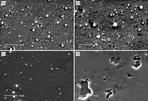
Fig.2 Surface morphologies of Cr2O3 coatings deposited at various O2 partial pressures: (a) 0 Pa; (b) 0.05 Pa; (c) 0.10 Pa; (d) 0.20 Pa
that of pure Cr while Cr2O3 has a much higher melting point than pure Cr. It had been reported that the metal with high melting point gave rise to a slighter droplet contamination than the metal with a low melting point [10], which explains the contrary effluence of reactive gas partial on droplet formation of CrN and Cr2O3.
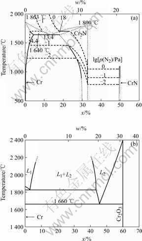
Fig.3 Binary phase diagrams of Cr��N (a) and Cr��O (b)
3.2 Deposition rate
Fig.4 shows the deposition rates of CrN and Cr2O3 coatings at various reactive gas partial pressure. The results indicated that the deposition rate of CrN initially increased dramatically with increasing nitrogen partial pressure and then kept almost unchanged and the deposition rate of Cr2O3 first decreased obviously and then slightly when O2 partial pressure increased. Similarly the ��target poisoning�� accounts for the change of deposition rate. The evaporation rate of Cr2O3 is much higher than that of pure Cr and the evaporation rate of CrN is far lower than that of pure Cr, which accounts for the initial change of the deposition rate. After a complete thin layer of nitride or oxide film is formed on the target surface, the deposition rate will show little change since the evaporation rate of target material keeps almost
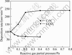
Fig.4 Deposition rate versus reactive gas partial pressure
unchanged.
3.3 Phase structure
Typical X-ray diffraction patterns of CrN and Cr2O3 coatings deposited under various reactive gas partial pressures are shown in Fig.5. When no reactive gas was introduced, BBC-Cr coating was obtained. For CrN, when N2 partial pressure got up to higher than 0.1 Pa, complete CrN of B1 NaCl structure was formed. The (111) and (220) textures were found to be the competitive orientations and the (220) texture became weaker and (111) stronger as the nitrogen partial pressure was raised. The melting point (Tm) of CrN is only about 1 000 �� and the deposition temperature is above 0.25 Tm, thus the atoms of formed coating have some ability of diffusion, which is in favor of the growth of the close-packed (111) plane. For Cr2O3, with increasing O2 partial pressure, the peaks of XRD pattern shifted to lower diffraction angle and the (006) texture weakened while the (300) texture increased. The lattice distance paralleled with substrate surface is 1.5%-1.7% bigger than the corresponding lattice distance of bulk Cr2O3, signifying a high compressive stress existed in the coating. With increasing O2 partial pressure, the compressive stress of the Cr2O3 coating increased and which accounted for the peel of the coating when O2 partial pressure exceeded 0.2 Pa. The transformation of (006) texture to (300) is in favor of release of compressive stress.
4 Conclusions
During the process of deposition of CrN or Cr2O3 coatings, correspondingly, a thin layer of CrN with a lower melting point or Cr2O3 with a higher melting point is formed on the surface of the Cr target. Due to the contrary change of the melting point of the target, the
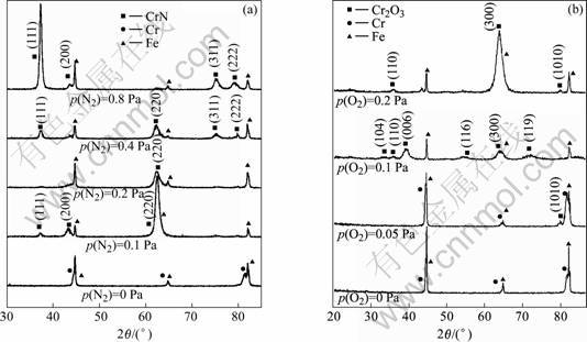
Fig.5XRD patterns of CrN(a) and Cr2O3(b) deposited at various reactive gas partial pressure
droplet formation, the deposition rate and the orientation of CrN and that of Cr2O3 exhibits opposite change trend with increasing reactive gas partial pressure. The optimized N2 partial pressure for CrN deposition is about 0.1-0.2 Pa in order to suppress the formation of droplets and the suitable O2 partial pressure for Cr2O3 is approximately 0.1 Pa for the attempt to prevent the peel of the coatings.
References[1] LI M S, WANG F H. Effects of nitrogen partial pressure and pulse bias voltage on (Ti,Al)N coatings by arc ion plating [J]. Surface and Coatings Technology, 2003, 167: 197-201.
[2] SHIAO M H, SHIEU F S. A formation mechanism for the macroparticles in arc ion-plated TiN films [J]. Thin Solid Films, 2001, 386: 27-31.
[3] LACKNER J M, WALDHAUSER W, MAJOR B, MORGIEL J, MAJOR L, TAKAHASHI H, SHIBAYAMA T. Growth structure and growth defects in pulsed laser deposited Cr-CrNx-CrCxN1-x multilayer coatings [J]. Surface and Coatings Technology, 2006, 200: 3644-3649.
[4] KONDO A, OOGAMI T, SATO K. and TANAKA Y. Structure and properties of cathodic arc ion plated CrN coatings for copper machining cutting tools [J]. Surface and Coatings Technology, 2004, 177-178: 238-244.
[5] LEE D B, LEE Y C, KWON S C. High temperature oxidation of a CrN coating deposited on a steel substrate by ion plating [J]. Surface and Coatings Technology, 2001, 141: 227-231.
[6] CHANG Y Y, WANG D Y. Corrosion behavior of CrN coatings enhanced by niobium ion implantation [J]. Surface and Coatings Technology, 2004, 188-189: 478.
[7] JI A L, WANG W, SONG G H, WANG Q M, SUN C, WEN L S. Microstructures and mechanical properties of chromium oxide films by arc ion plating [J]. Materials Letters, 2004, 58: 1993-1998.
[8] WANG D Y, CHIU M. Characterization of Cr2O3/CrN duplex coatings for injection molding applications [J]. Surface and Coatings Technology, 2001, 137: 164-16.
[9] ANDERS A. Physics of arcing, and implications to sputter deposition [J]. Thin Solid Films, 2006, 502: 22-28.
[10] M?NZ W D, SMITH I J, LEWIS D B, CREASEY S. Droplet formation on steel substrates during cathodic steered arc metal ion etching [J]. Vacuum, 1997, 48: 473-481.
Foundation item: Projects (59971052; 50401022) supported by the National Natural Science Foundation of China
Corresponding author: LI Ming-sheng; Tel: +86-791-3801423; E-mail: mshli@163.com
