

Cutting force signal pattern recognition using hybrid neural network in end milling
Song-Tae SEONG1, Ko-Tae JO2, Young-Moon LEE3
1. Research and Development Department, Gyeongbuk Hybrid Technology Institute, Gyeongsangbuk-do, 730-701, Korea;
2. School of Mechanical Engineering, Yeongnam University, Gyeongsangbuk-do, 712-160, Korea;
3. School of Eechanical Engineering, Kyungpook National University, Daegu, 220-60, Korea
Received 2 March 2009; accepted 30 May 2009
Abstract:
Under certain cutting conditions in end milling, the signs of cutting forces change from positive to negative during a revolution of the tool. The change of force direction causes the cutting dynamics to be unstable which results in chatter vibration. Therefore, cutting force signal monitoring and classification are needed to determine the optimal cutting conditions and to improve the efficiency of cut. Artificial neural networks are powerful tools for solving highly complex and nonlinear problems. It can be divided into supervised and unsupervised learning machines based on the availability of a teacher. Hybrid neural network was introduced with both of functions of multilayer perceptron (MLP) trained with the back-propagation algorithm for monitoring and detecting abnormal state, and self organizing feature map (SOFM) for treating huge datum such as image processing and pattern recognition, for predicting and classifying cutting force signal patterns simultaneously. The validity of the results is verified with cutting experiments and simulation tests.
Key words:
end milling; cutting force signals; multilayer perceptrons (MLP); self organizing feature map (SOFM);
1 Introduction
End milling processes have been so widely used in precision machinery industries such as mechanical parts and die manufacturing. Several studies for end milling have been performed and reported [1-3]. Mattellotti [1]clarified geometric relationships between tool paths and cutting variables in end milling processes. Under certain cutting conditions, signs of cutting forces acquired by tool dynamometer change from positive to negative and vice versa during one revolution [4]. And it has been reported that chatter vibration can occur at the condition of relatively small axial depth cut [5].
Multilayer perceptron (MLP) which is a supervised neural network algorithm has been widely studied in the abnormal defect diagnosis of cutting process [6]. And self-organizing feature map (SOFM) is a very useful pattern recognition algorithm which selects the neuron whose randomized weight vectors match input vectors with the winning neuron and its neighborhood neurons [7-8].
In this study, the presence of cutting force reversal and chatter vibration are predicted, based on hybrid neural network combining SOFM neural network with multilayer perceptron (MLP) algorithm. For improving the quality of the classification performance. And the cutting experiments and simulation tests are carried out on commercially available aluminum AL6061 and SM45C to verify the validity of cutting force signal pattern recognition.
2 Cutting force signals in end milling
Fig.1 illustrates a down end milling process.
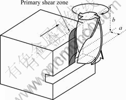
Fig.1 Schematic diagram of down end-milling process
In this study, the cutting action of tool bottom edges is prevented by using a grooved workpiece, as shown in Fig.1.
Fig.2(a) and (b) show the measured and predicted cutting forces when the radial depth of cut, Dr, are 3 and 4 mm respectively. In both cases, the axial depth of cut, Da, is 7 mm.
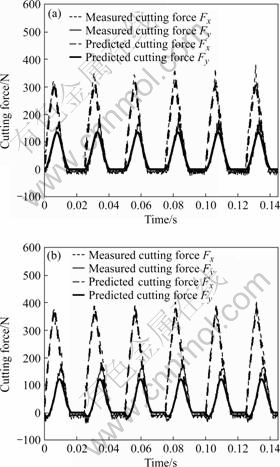
Fig.2 Two cases of cutting force signals acquired by tool dynamometer (axial depth of cut, Da=7 mm) (a) Dr=3 mm; (b) Dr=4 mm
When the radial depth of cut, Dr, is 4 mm, the cutting force component experiences minus values right after cutting edge enters the workpiece as seen in the figure.
The mechanism of such a cutting force reversal can be explained by a cutting force coordinate.
Fig.3(a) and (b) show the variations of resultant cutting force direction during one revolution of cutting tool. In the figures, the abscissas represent the cutting force component Fy, while the ordinates represent the cutting force component Fx.
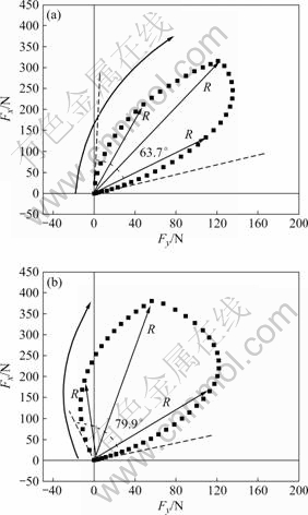
Fig.3 Variations of resultant cutting force angle and its direction with respect to tool rotation: (a) Dr=3 mm(AL6061); (b) Dr=4 mm(AL6061)
As seen in the figures, varying extent of resultant cutting force, R increases from 63.7? to 79.9? when the radial depth of cut, Dr, increases from 3 to 4 mm. When Dr is 3 mm, resultant cutting force vectors occupy only in the first quadrant of force coordinates. But in case Dr is 4 mm, the vectors occupy the second quadrant except for the first one [9].
Fig.4 shows simulated cutting force Fy according to the variation of the specific cutting resistance of tangential direction, Kt, when the axial depth of cut, Da, is 7 mm, radial depth of cut, Dr, is 2 mm and the specific cutting resistance of radial direction, Kr, is 1 161.9 N/mm2, respectively.
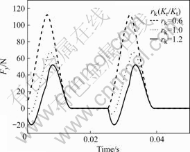
Fig.4 Relationships between simulated cutting force Fy and time
As shown in the figure, the cutting force reversal can also occur when the ratio of the specific cutting resistance of tangential and radial direction, rk, is relatively large.
These cases have been reported when cutting difficult-to-cut materials such as Inconnel [9].
Fig.5 shows the cutting forces with their high frequency components when the radial depth of cut, Da (4 mm) is the same to the case in Fig.2(b), but the axial depth of cut, Da (0.6 mm) is much smaller.
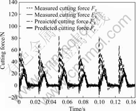
Fig.5 High frequency components in cutting force curves (Dr= 4 mm, Da=0.6 mm)
From the figure, it is observed that much more high frequency components in the force curves and the relative magnitudes of minus force components are much larger than those in Fig.2(b). This cutting force reversal is to be an important factor to induce chatter vibration during cutting process.
3 Hybrid neural network methodology
3.1 Multilayer perceptrons (MLP)
MLP network consists of sensory units that constitute the input, one or more hidden and output layers of computation nodes. And the model of each neuron in the network includes a nonlinear activation function.
Fig.6 illustrates the architecture of MLP with two hidden layers.
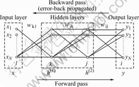
Fig.6 Two passes of MLP (x: input vector; y: output vector; w: synapticweight; l: input layer; k, j: hidden layer; i: outputlayer; h: signoidfunction)
As shown in the figure, MLP network consists of two passes, a forward pass and a backward pass. During the forward pass, input vectors are applied to the sensory nodes and its effect propagates through the network layer to layer. Finally, outputs are produced as the actual response and the synaptic weights are all fixed. On the other hand, during the backward pass, the synaptic weights are all adjusted in accordance with an error-correction rule [10].
3.2 Self organizing feature map (SOFM)
The principal goal of the SOFM is to transform an incoming signal pattern of arbitrary dimension into one or two dimensional discrete map, and to perform this transformation adaptively in a topologically ordered fashion. Fig.7 illustrates the SOFM the model.
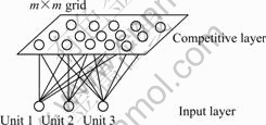
Fig.7 Architecture of SOFM model based on competitive learning
As shown in the figure, the network consists of input layer and competitive layer where the topological ordering of the weight vectors takes place.
Therefore, SOFM is converged with an accurate statistical quantification of the input space, and its synaptic weights are updated by
![]() (1)
(1)
where m is a synaptic mass, �� is a learning rate and Z is a Gaussian neighborhood function [10].
3.3 Hybrid neural network
Fig.8 illustrates the hybrid neural network with both functions of MLP and SOFM.
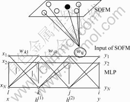
Fig.8 Hybrid neural network
SOFM combines with MLP by using the final learned mass with both of input and output information, nearest to output in MLP as input of SOFM. If new input vectors are applied to the network, output vectors are predicted in MLP part and classified in SOFM algorithm.
4 Cutting experiments
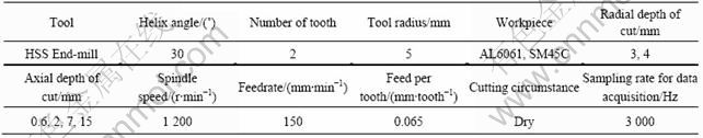
Table 1 shows the tool geometry and cutting conditions. The experiments were carried out under different cutting conditions to investigate the force reversal and chatter vibration.
Table 1 Cutting input conditions
5 Results and discussion
5.1 Cutting experiment results
Table 2 presents input data for training in network.
Table 2 Input data for training in network
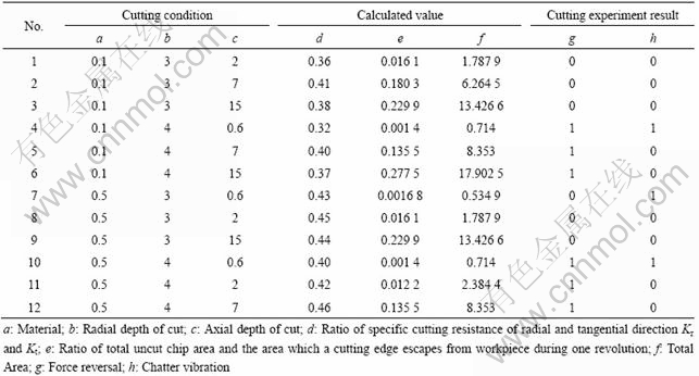
As shown in the table, AL6061 and SM45C are set as 0.1 and 0.5, respectively, and if there is a cutting force reversal and chatter vibration occurs, the value is set as one, otherwise, 0.
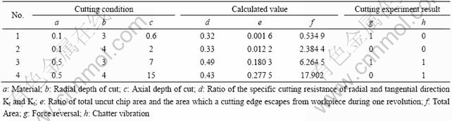
Table 3 shows the rest of cutting experiment results except for 12 training input values of total 16 tests. This data are used for testing in the hybrid neural network.
Table 3 Data sets for testing hybrid neural network
5.2 Learning process in MLP
Fig.9 shows the performance of learning using MLP.
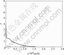
Fig.9 Learning performance in MLP
As shown in the figure, the error is converged to 0 for 16 000 epochs when hidden layers are 2, the hidden nodes of hidden layers are 11 each and learning rate is 0.01.
5.3 Learning process in SOFM
Fig.10 shows the convergence phase in a two-dimensional lattice of 12��12.
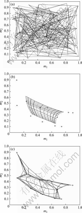
Fig.10 Convergence of SOFM: (a) Initial mass; (b) Iteration 5%; (c) End of convergence
Fig.10(a) shows the initial condition of the two dimensional lattice and Fig.10(b) shows the condition of the lattice at 500 iterations. Fig.10(c) shows the condition of the lattice at the end of convergence phase.
Fig.10(a) and (b) show the learning results in SOFM and computer experiment for classification after 10 000 iterations.
5.4 Comparison of cutting experiment and simulation
Table 4 shows the comparison of cutting experiment and computer simulation results.
Table 4 Comparison of experiment and simulation results
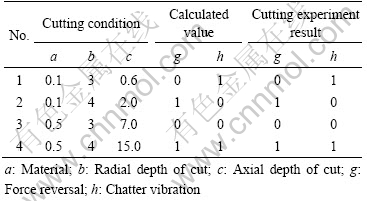
The prediction results are completely matching well with the cutting experiment results as shown in Table 4.
As shown in Fig.11, recognized patterns are in coincidence with the patterns presented in Table 2.
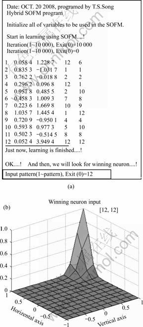
Fig.11 Computer experiment for adaptive pattern classification
(a) Learning results in SOFM; (b) Gaussian neighborhood function centered on winning neuron of 12th pattern
6 Conclusions
1) Hybrid neural network combining MLP and SOFM algorithms is introduced for predicting and classifying cutting force signal patterns simultaneously.
2) Both the cutting force reversal signal and chatter vibration occurrence signal pattern in end milling are predicted and classified perfectly by hybrid neural network.
References
[1] MARTELLOTTI M E. An analysis of the milling process [J]. Trans of ASME, 1941, 63: 677-700.
[2] TLUSTY J, MACNEIL P. Dynamics of cutting forces in end milling [J]. Annals of CIRP,1975, 24(1): 21-25.
[3] LEE Y M, SONG T S, SIM B K. The shear and friction characteristics analysis of end-milling [J]. Journal of Korean Soc Mech Eng, 2001, 25(10): 1520-1527.
[4] SONG T S, KO T J, KIM H S, LEE J H. Study on the change of cutting force direction in end milling [J]. Journal of Korean Soc Precision Eng, 2007, 24(10): 37-45.
[5] SONG T S, KO T J, LEE Y M. Mechanisms of cutting force direction change and vibration occurrence in end milling [C]// Internal Conference on Advanced Materials, Development and Performance, 2008: 83.
[6] LIM K Y, MUN S D, KIM S I, KIM T Y. A study on damage detection of cutting tool using neural network and cutting force signal [J]. Journal of Korean Soc Precision Eng, 1997, 14(12): 48-55.
[7] KOHONEN T. The self-organizing map [J]. Proc of the IEEE, 1990, 78: 1464-1480.
[8] KOHONEN T. The self-organizing map [J]. Neuro-computing, 1998, 21: 1-6.
[9] LEE Y M, LEE S H, TAE W I, KWON O J, CHOI B H. Cutting force variation of inconel 718 in up and down end milling with different helix angles [J]. Journal of Korean Soc Precision Eng, 2001, 18(7): 143-148.
[10] HAYKIN S. Neural networks, 2/E: A comprehensive foundation [M]. Prentice Hall, 1998.
Corresponding author: Young-Moon LEE; Tel: +82-53-950-5574; Fax: +82-53-950-6550; E-mail: ymlee@knu.ac.kr
(Edited by CHEN Ai-hua)
[1] MARTELLOTTI M E. An analysis of the milling process [J]. Trans of ASME, 1941, 63: 677-700.
[7] KOHONEN T. The self-organizing map [J]. Proc of the IEEE, 1990, 78: 1464-1480.
[8] KOHONEN T. The self-organizing map [J]. Neuro-computing, 1998, 21: 1-6.
[10] HAYKIN S. Neural networks, 2/E: A comprehensive foundation [M]. Prentice Hall, 1998.
