
Trans. Nonferrous Met. Soc. China 22(2012) s376-s381
Effect of internal pressure on corner radius and thickness distribution of shear hydro-bending of 5A02 aluminum alloy tube
WANG Yong, HAN Cong, YUAN Shi-jian
National Key Laboratory for Precision Hot Processing of Metals, Harbin Institute of Technology, Harbin 150001, China
Received 28 August 2012; accepted 25 October 2012
Abstract:
The effects of internal pressure on forming defects, corner radius and thickness distribution of 5A02 aluminum alloy shear hydro-bending tubes were studied by experiment. Numerical simulation was conducted to analyze the effect of internal pressure on axial strain and invariable lines of thickness strain. The ultra-small bending tubes were successfully manufactured when the relative internal pressure, ratio of internal pressure and yield stress of the material, is higher than 0.2. The relative bending radius of the first outer corner decreases from 0.3 to 0.025 when the relative internal pressure increases from 0.2 to 1.2. The axial thickness distribution is different in intrados and extrados. The changing rate of thickness is larger with a higher internal pressure. The minimum thickness decreases from 1.45 mm to 0.87 mm when the relative internal pressure changes from 0.2 to 1.2. The tube is divided into feeding zone, the first corner, shearing zone, the second corner and holding zone. The strain of feeding zone and the first corner is compressive caused by the feeding. The strain of the second corner and holding zone is tensile for far away from feeding punches. The strain of shearing zone changes from compressive to tensile with rising of internal pressure. On one hand, the smaller corner radius formed by higher internal pressure blocks the feeding. On the other hand, the corner filling strengthens the extensive strain of shearing zone. In the feeding zone and holding zone, thickness strain is positive, and the tube thickens. In the corner and shear zones, thickness strain is negative, and the tube thins.
Key words:
aluminum alloy; shear hydro-bending; small bending radius tube; internal pressure; 3D numerical simulation;
1 Introduction
Thin-walled tube bending plays an important role in pipe transportation, aeronautics and aerospace engineering due to light weight and low cost [1-3]. With the development of unmanned aerial vehicles and advance aero turbine, aluminum and titanium alloy tubes with small bending radius are required for the space-saving [4-6]. Small bending radius tubes manufactured integrally are more reliable and weight- saving compared with welding parts. When the bending radius is small, the tensile deformation of the outer corner is so large that the thinning is severe even to cause rupture. At the same time, the compressive deformation of the inner corner is also too large and the severely thickening takes place. Moreover, wrinkling may appear. In addition, the distortion of cross-section is more serious with the increase in deformation [7,8].
The limit of relative bending radius of computer numerical control (CNC) bending is 1.5 by using special mandrel and tooling [9,10]. A push-bending was proposed to manufacture aluminum alloy tubes with relative bending radius of 1.0 [11]. However, CNC bending, push bending and other conventional bending technologies cannot manufacture tube with relative bending radius smaller than 1.0. GOODARZI et al [12] proposed shear bending of a Z-typed tube with a mandrel, but the cross-section ovality reduces the dimensional accuracy without internal supporting [13].
A shear hydro-bending method was proposed to solve the problem of forming ultra-small bending radius tube [14]. Differing from the traditional bending process of tensile-compressive deformation mechanism, shear deformation is employed in shear hydro-bending process to form the ultra-small bending radius tube [15]. And also the shear deformation is benefit to the grain refinement which was investigated by electron back scattered diffraction (EBSD) [16]. Compared with the shear bending with a mandrel, the shear hydro-bending improves apparently the distortion of cross-section of the bent tube with the liquid medium supporting. The internal pressure is a key factor to the forming of shear hydro-bent tube. But the effects of internal pressure on defects, corner radius and thickness distribution of shear hydro-bending tube are rarely reported.
In this work, numerical simulation and experiments were conducted to investigate the effect of internal pressure on forming defects, corner radius and thickness distribution of shear hydro-bending of 5A02 aluminum alloys tube. The thickness distribution of axial direction and invariable lines of radial strain were analyzed.
2 Material and methods
2.1 Mechanical properties
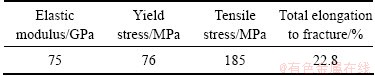
The 5A02 aluminum alloy tube with the out diameter of 30 mm and wall thickness of 1.5 mm was employed in the experiment. Table 1 shows the mechanical properties of the tube which were obtained by uniaxial tensile tests with specimens cut along axial direction.
Table 1 Mechanical properties of 5A02 aluminum alloy tube
2.2 Experimental setup
The experiment was conducted in the hydroforming machine manufactured by Harbin Institute of Technology (HIT, China). The shear hydro-bending tooling includes left punch, right punch, fixed die and movable die, as shown in Fig. 1. Axial feeding and tangential stroke were employed to achieve a small bending radius tube by punches and movable die with the supporting of liquid medium. The internal pressure p and axial feeding S1 and tangential stroke S2 play an important role in shear hydro-bending process. Relative internal pressure p'=p/��s is introduced to evaluate the internal pressure. Effects of internal pressure on defects, corner radius and thickness distribution are investigated by fixing S1 equal to S2 and changing relative internal pressure p'.
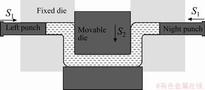
Fig. 1 Schematic diagram of shear hydro-bending
2.3 Finite element model
The 3D finite element analysis code ABAQUS 6.10
was employed to study the hydro-bending process numerically. Apart from the tube, the finite element model comprises left punch, right punch, fixed die and movable die, as shown in Fig. 2. The tube consisted of 108720 linear brick element of type C3D8R. Friction between the contact surfaces was modeled with a friction coefficient of 0.1. A constant pressure was applied to the internal surface of the tube. Local cylindrical coordinate was applied to the tube, where ��, t and z correspond to circumferential direction, radial direction and axial direction, respectively.
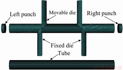
Fig. 2 Finite element model
3 Experimental results
3.1 Effect of internal pressure on wrinkle
Wrinkle is a typical defect in shear hydro-bending. It is caused by the compressive load of internal pressure and axial feeding. When the feeding is fixed, wrinkle occurs at the corner of bending tube if the internal pressure is too low to provide enough supporting. Figure 3 shows the effect of internal pressure on wrinkle. Wrinkle takes place when the relative pressure p' is smaller than 0.1, as shown in Fig. 3(a). When the relative internal pressure p' is higher than 0.2, the shear hydro-bending tube can be manufactured successfully, as shown in Fig. 3(b). The internal pressure limit is related to the yield pressure of the bending tube. The yield pressure of closed end tube can be calculated by
 (1)
(1)
In this work, t=1.5 mm, r=15 mm, so the yield pressure ps=0.1��s. When the relative internal pressure is higher than 0.1, the supporting of liquid medium is enough to avoid the wrinkle and form the ultra small bending radius tube .
3.2 Effect of internal pressure on corner radius
Due to the central symmetry, one quarter of the hydro shear-bent tube was developed for further discussion. There are two corners in shear hydro-bending tube. R1 and r1 are outer and inner corner radii of the first corner, respectively. R2 and r2 are outer and inner corner radii of the second corner, respectively. Inner corners r1 and r2 are contact to the die surfaces during the forming process and the corner radius of tube is equal to 3 mm, the corner radius of the die.
The effects of internal pressure on the first outer corner radius R1 and the second outer corner radius R2 are shown in Fig. 4.
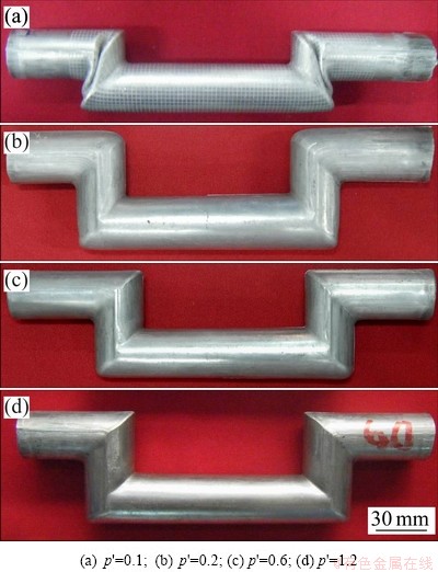
Fig. 3 Effect of internal pressure on wrinkle
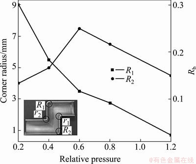
Fig. 4 Effect of internal pressure on corner radius
When the relative internal pressure p' is 0.2, R1 and R2 are 9 mm and 4 mm, respectively. The first outer corner radius R1 decreases with the increase in relative pressure p'. The second outer corner radius R2 does not change so much. When the relative pressure p' is up to 1.2, the first outer corner radius R1 and the second outer corner radius R2 are 0.75 mm and 4.5 mm, respectively. The relative bending radius Rb of the formed tube is 0.3 under the condition that the relative pressure p' is 0.2, while it is 0.02 when the relative pressure is 1.2.
3.3 Effect of internal pressure on thickness distribution
The side close to the movable die is taken as intrados, and the other side is taken as extrados. 20 measured points are selected along axial direction of the one quarter tube for thickness measurement, as shown in Fig. 5. Five zones are divided by deformation characters: feeding zone (points 1-6), the first corner (points 6-8), shearing zone (points 8-13), the second corner (points 13-15) and holding zone (points 15-20).
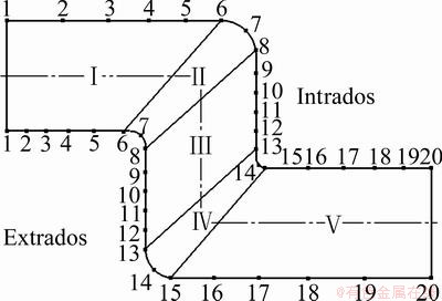
Fig. 5 Distribution of measured points
The shear hydro-bent tubes with relative pressures of 0.2, 0.6 and 1.2 are selected for thickness measurements. Figure 6(a) shows the thickness distribution of both sides under a relative pressure of 0.2. The thickness of the feeding zone is thickened, caused by the feeding of punches. It decreases with the distance of tube ends. The tendencies of thickness variation are the same in the first corner zone and the second corner zone on both sides. In the inner corner zone, the material is accumulated, which leads to thickening. While in the outer corner zone it is tensile and leads to thinning. The maximum and minimum thicknesses of intrados located at points 14 and 7 are 2.04 mm and 1.45 mm, respectively. The thickening ratio is 35.67% and the thinning ratio is 3.67%. The maximum thickness of extrados located at point 7 is 1.81 mm. The thickening ratio is 20.33%. The shear zone is the transition of two corner zones. The thickness of holding zone is approximate to that of the original tube.
The tendencies of thickness distribution of both sides are almost the same under different internal pressures. Figure 6 shows the thickness distribution with the relative pressures of 0.4, 0.6, and 1.2. The amplitude of variation is larger with a higher internal pressure. The minimum thickness of intrados is decreased from 1.45 mm to 0.85 mm when the relative pressure rises from 0.2 to 1.2. The maximum thinning ratio rises from 3.67% to 43.33%.
The thickness of shearing zone is decreased when the internal pressure is higher. This is mainly caused by the small outer radius formed by a high pressure. Feeding on the ends is blocked by the outer corner. The location of minimum thickness transfers from points 7 to 8 when the relative internal pressure rises from 0.2 to 0.6. When the relative internal pressure reaches 1.2, the location of minimum thickness is at point 10. This transverse is also caused by the reduction of R1. On one hand, the feeding of punches is blocked by the outer corner. Feeding material cannot reach shearing zone. On the other hand, the corner filling of R1 also strengthens the extensive stress of shearing zone.
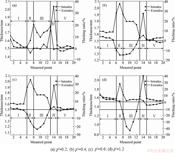
Fig. 6 Thickness distribution of 5A02 shear hydro-bending tube under different relative internal pressures
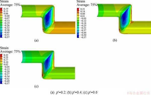
Fig. 7 Axial strain distribution with different relative internal pressures
4 Numerical simulation
4.1 Effect of internal pressure on axial strain
The distributions of the axial strain under different internal pressures are shown in Fig. 7. It can be seen that the tensile strain is the maximum in the second outer corner due to the bulging effect of internal pressure. In addition, the feeding is smaller than that of the first corner because of blocking by the first inner corner r1. The maximum compressive strain locates at the shearing zone, and the maximum value of the compressive strain is larger than that of the tensile strain. The distribution and variation of the axial strain are similar to those under the different internal pressures. However, the tensile strain is larger when the internal pressure is higher. The internal pressure has little effect on the maximum value of compressive strain.
To observe more clearly the effect of internal pressure on axial strain, the variations of axial strain along intrados and extrados with different internal pressures are shown in Fig. 8. It can be seen that the variations of axial strain on both sides are similar when the internal pressure rises from 0.2 to 0.6. In the feeding zone and the first corner zone, the axial strain is compressive caused by the feeding of punches. The value of strain is larger when the internal pressure is higher. On one hand, the smaller corner radius formed by higher internal pressure blocks the feeding on the ends. On the other hand, the corner filling of R1 also strengthens the extensive stress of shearing zone. Both these two reasons make the accumulation of material in the feeding zone more serious. The axial strain changes from compressive to tensile in the shearing zone. The holding zone is far away from main deformation zone. The trend of axial strain distribution in the holding zone varies a little when the internal pressure increases from 0.2 to 0.6.
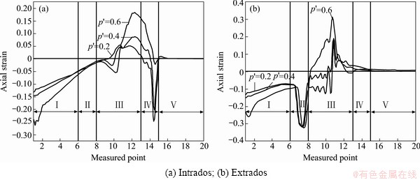
Fig. 8 Variation of axial strain with different relative internal pressure
4.2 Invariable line of strain in thickness direction
During the shear hydro-bending, the inner corner thickens which is caused by compressive stress and the outer corner thins which is caused by tensile stress. There is a thickness invariable line on the tube corresponding to the line that thickness strain is equal to 0. On one side of the line the thickness strain is positive, d��t��0 and the tube is thickened. On the other side of the line, the thickness strain is negative, d��t��0 and the tube is thinned. Figure 9 shows the distribution of thickness strain of the entire tube. With the strain invariable line, the thickness distribution of the integral tube is illustrated. The tube is divided into three zones by the two lines, as shown in Fig. 10. At the two ends and in the holding zone, the thickness strain is positive and the tube is thickened. In the corners and shear zones, the thickness strain is negative and the tube is thinned.

Fig. 9 Thickness strain distribution (p'=0.4)
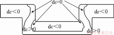
Fig. 10 Three typical zones of thickness strain (p'=0.4)
5 Conclusions
1) The ultra-small 5A02 aluminum alloy tube was successfully manufactured when the relative internal pressure was higher than 0.2. If the relative internal pressure is lower than 0.2, the liquid medium cannot provide enough supporting and wrinkle takes place on the first corner.
2) The first outer corner radius decreases rapidly with the increase in internal pressure. The first outer corner radius is 9 mm and the relative bending radius is 0.3 when the relative internal pressure is 0.2. The first outer corner radius is 0.75 mm and the relative bending radius is 0.025 when the relative internal pressure is 1.2.
3) The axial thickness distribution is different in intrados and extrados. The change rate of wall thickness is larger when internal pressure is higher. The maximum thinning ratio rises from 3.67% to 43.33% when the relative internal pressure changes from 0.2 to 1.2. The maximum thinning point transfers from out corner to the shearing zone.
References
[1] YU C L, LI X Q. Theoretical analysis on springback of L-section extrusion in rotary stretch bending process [J]. Transactions of Nonferrous Metals Society of China, 2011, 21(12): 2705-2710.
[2] HASHMI M S J. Aspects of tube and pipe manufacturing processes: Meter to nanometer diameter [J]. Journal of Materials Processing Technology, 2006, 179: 5�C10.
[3] WELO T, WIDER E F. Precision bending of high-quality components for volume applications [J]. Transactions of Nonferrous Metals Society of China, 2010, 20(11): 2100-2110.
[4] YUAN S J, WANG X S, LIU G, WANG Z R. Control and use of wrinkles in tube hydroforming [J]. Journal of Materials Processing Technology, 2007, 182: 6-11.
[5] GUAN Y, POURBOGHRAT F, BARLAT F. Finite element modeling of tube hydroforming of polycrystalline aluminum alloy extrusions [J]. International Journal of Plasticity, 2006, 22: 2366-2393.
[6] AHMETOGLU M, ALTAN T. Tube hydroforming: State-of-the-art and future trends [J]. Journal of Materials Processing Technology, 2000, 98: 25-33.
[7] MATHON C, LIMAM A. Experimental collapse of thin cylindrical shells submitted to internal pressure and pure bending [J]. Thin-Walled Structure, 2006, 44: 39-50.
[8] CHITAWADAGI M V, NARASIMHAN M C. Strength deformation behavior of circular concrete filled steel tubes subjected to pure bending [J]. J Constr Steel Res, 2009, 65: 1836-1845.
[9] LI C, YANG H, ZHAN M, XU X D, LI G J. Effects of process parameters on numerical control bending process for large diameter thin-walled aluminum alloy tubes [J]. Transactions of Nonferrous Metals Society of China, 2009, 19(3): 668-673.
[10] LI H, YANG H, YAN J. Numerical study on deformation behaviors of thin-walled tube NC bending with large diameter and small bending radius [J]. Computational Materials Science, 2009, 45: 921-934.
[11] ZENG Y S, LI Z Q. Experimental research on the tube push-bending process [J]. Journal of Materials Processing Technology, 2002, 122: 237-240.
[12] GOODARZI M, KUBOKI T, MURATA M. Effect of initial thickness on shear bending process of circular tubes [J]. Journal of Materials Processing Technology, 2007, 191: 136-140.
[13] TANAKA M, MICHINO M, SANO K, NARITA M. Pipe bending technology with zero bending radius [J]. Journal of Society for the Technology Plasticity, 1994, 35(398): 232.
[14] HAN C, XU Y C, YUAN S J, WANG Y. Effect of feeding pressure on hydroforming of crank-shaped tubes with ultra-small bending radius [J]. Steel Research Int, 2010, 81(9): 520-523.
[15] YUAN S J, HAN C, WANG Y, YANG S. Hydro-bending of light alloy tubes [J]. Steel Research Int, 2011(Special Edition): 361-366.
[16] HAN C, WANG Y, XU Y C, YUAN S J. Effect of internal pressure on microstructure of tube shear hydro-bending of 5A02 aluminum alloys [J]. Transactions of Nonferrous Metals Society of China, 2011, 21: 429-433.
��ѹ��5A02���Ͻ��Һ���������ܳ��κͱں�ֲ���Ӱ��
�� �£��� �ϣ�Է����
��������ҵ��ѧ ���������ȼӹ����Ҽ��ص�ʵ���ң������� 150001
ժ Ҫ��Ϊ���о���ѹ��5A02���Ͻ��Һ�����ܳ��κͱں��Ӱ�죬ͨ��ʵ��ķ����о���ѹ��5A02���Ͻ��Һ���������ܳ���ȱ�ݡ�����Բ�Ǻ�����ں�ֲ���Ӱ�졣ͨ����ֵģ���������ѹ������Ӧ���Ӱ��ͺ���Ӧ�䲻�����ڳ��ιܼ��ϵķֲ�������������������ѹ(������ѹ���������ǿ�ȵı�)����0.2ʱ���ܹ�˳�����Ρ��������ѹ��0.2����1.2ʱ����һ�����Բ�Ƕ�Ӧ����������뾶��0.3���͵�0.025��������С�ں���1.45 mm���͵�0.87 mm�����ݱ����ص���Խ���Һ���������ܷ�Ϊ����������һ��ǡ����������ڶ���Ǻͼг������������ϵ������£��������͵�һ�������ΪѹӦ�䡣Զ�벹�����ĵڶ���Ǻͼг�����ҪΪ��Ӧ�䡣������ѹ��������������Ӧ����ѹӦ����Ϊ��Ӧ�䡣һ���棬��ѹԽ����Բ��ԽС���������ϵ��谭���ø�ǿ����һ���棬����СԲ��ʱ�����˶����������Ӧ�䡣���ݺ���Ӧ���ص���Խ���Һ���������ܼ���Ϊ�������ͼ��������������ѹΪ0.4ʱ��������Ϊ���϶˺ͼгֶˣ�������λ������ǵ���Բ�Ǵ��ͼ�������
�ؼ��ʣ����Ͻ𣻳�Һ������������С�뾶��ܣ���ѹ����ά��ֵģ��
(Edited by YANG Hua)
Foundation item: Project (51075097) supported by the National Natural Science Foundation of China
Corresponding author: HAN Cong; Tel: +86-451-86415754; E-mail: conghan@hit.edu.cn
DOI: 10.1016/S1003-6326(12)61734-8
Abstract: The effects of internal pressure on forming defects, corner radius and thickness distribution of 5A02 aluminum alloy shear hydro-bending tubes were studied by experiment. Numerical simulation was conducted to analyze the effect of internal pressure on axial strain and invariable lines of thickness strain. The ultra-small bending tubes were successfully manufactured when the relative internal pressure, ratio of internal pressure and yield stress of the material, is higher than 0.2. The relative bending radius of the first outer corner decreases from 0.3 to 0.025 when the relative internal pressure increases from 0.2 to 1.2. The axial thickness distribution is different in intrados and extrados. The changing rate of thickness is larger with a higher internal pressure. The minimum thickness decreases from 1.45 mm to 0.87 mm when the relative internal pressure changes from 0.2 to 1.2. The tube is divided into feeding zone, the first corner, shearing zone, the second corner and holding zone. The strain of feeding zone and the first corner is compressive caused by the feeding. The strain of the second corner and holding zone is tensile for far away from feeding punches. The strain of shearing zone changes from compressive to tensile with rising of internal pressure. On one hand, the smaller corner radius formed by higher internal pressure blocks the feeding. On the other hand, the corner filling strengthens the extensive strain of shearing zone. In the feeding zone and holding zone, thickness strain is positive, and the tube thickens. In the corner and shear zones, thickness strain is negative, and the tube thins.
