

Failure mechanism of EB-PVD thermal barrier coatings on NiAl substrate
LI He-fei(��Ϸ�), GUO Hong-bo(���鲨), GONG Sheng-kai(������)
School of Materials Science and Engineering, Beihang University, Beijing 100083, China
Received 13 July 2006; accepted 28 May 2007
Abstract:
Yttria stabilized zirconia(YSZ) was deposited on the line cut ��-NiAl substrate by electron-beam physical vapour deposition(EB-PVD), and the cyclic oxidation behaviors of thermal barrier coatings on ��-NiAl substrate were investigated in 1 h thermal cycles at 1 200 �� in air. The results show that the samples fail after 80-100 cycles. Sub-interface cavitations in the substrate develop due to depletion of Al in forming thermally grown oxides(TGOs). The collapse and closing up of cavities result in the ragged YSZ/TGO/substrate interface. Since the specific crack trajectories are quite sensitive to local geometry, cracks along the YSZ/TGO/substrate interfaces ultimately lead to YSZ spallation.
Key words:
EB-PVD; NiAl; TBCs; cyclic oxidation;
1 Introduction
Thermal barrier coatings(TBC) are essential in improving the efficiency and life expectancy of jet engines for aero industry as well as of gas turbines for power generation[1-2]. With advanced thermal barrier coatings, combustion liners, vanes, even the leading edges of blades can now be coated[1-4]. In combination with internal cooling, a drop of 150 �� can be achieved across the TBC[3]. Typical TBC systems consist of a nickel-base superalloy substrate that is the turbine component, coated with a MCrAlY (M represents Fe,Co,Ni or both), or diffusion aluminide bond coat, on which a yttria-stabilized zirconia(YSZ) TBC is deposited [5-8]. The metallic coating is needed to provide adhesion between the ceramic coat and the substrate, and to give corrosion protection to the substrate by the formation of thermally grown oxide(TGO) during fabrication and service.
The intermetallic NiAl bond coat has attracted a great deal of attention for its high temperature performance[9]. The use of ��-NiAl bond coat in TBC systems has the advantage of preferential growth of ��-Al2O3 as the TGO. Although there were many studies on the addition of reactive elements(REs) to the NiAl bond coat to improve the adhesion of TGO to the coating, few authors reported the cyclic oxidation performance of the thermal barrier coatings on NiAl substrate. The current study focuses on a NiAl substrate with EB-PVD TBC and investigates its cyclic oxidation behavior.
The ceramic coat of TBC is 7%-8% (mass fraction) yttria stabilized zirconia(YSZ) since this ceramic coat is the current state-of-the-art.
2 Experimental
As shown in Fig.1, the EB-PVD facility used for YSZ deposition contains four electron guns altogether. Only two of four guns are used in this experiment, one for vaporization of YSZ and the other for substrate heating.
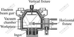
Fig.1 EU-205 EB-PVD coater and operating principle
The nominal composition of ��-NiAl ingot is an alloy ingot containing Ni-30.84% Al. The samples with the size of 12 mm��10 mm��3 mm were cut using spark erosion from the NiAl ingot. All the samples were ultrasonic cleaned by acetone and ethanol for 10 min, respectively. During EB-PVD, the samples were fixed on the fixture and mounted on the rotated mechanical arm of vacuum chamber with rotation speed of 14 r/min. In vacuum chamber, the samples were preheated by the electron beam to the pre-defined temperature (approx. 850 ��) which was monitored by a thermal couple fixed onto the fixture. The yttria stabilized zirconia (ZrO2+7% Y2O3) layer with a thickness of 150-200 ?m was deposited by EB-PVD with the deposition rate of 3 ��m/min.
After deposition of TBC, all the samples were then submitted to cyclic test. The cyclic oxidation was conducted in an automated furnace rig. Each cycle consisted of a 10 min heating up to 1 200 ��, a 40 min exposure at 1 200 �� for 40 min, followed by a 10 min cooling in air.
Characterization of the representative samples was carried out using scanning electron microscopy(SEM) equipped with energy dispersive spectroscopy(EDS).
3 Results and discussion
Figs.2(a) and (b) show the cross-sectional SEM morphologies of the sample under the as-deposited condition. As mentioned above, the NiAl substrate used were cut from the NiAl ingot for NiAl evaporation, and there existed severe melting pre-existed defects in the substrate. Fig.2(a) shows the uniform flat surface morphology and the overall cross section of the as-deposited specimen with a 200 ��m-thick YSZ top coating. From the magnified cross-sectional images shown in Figs.2(b) and (c), it is evident that defects like large cavities and holes can be found inside the YSZ coating. There exist severe defects in the substrate, like pores or holes, which resulting in the large cavities either on the surface of or within the substrate. These surface defects may connect those inside the substrate. With EB-PVD deposition, the YSZ deposit typically exhibits a columnar morphology, which is the key for in-plane strain accommodation caused by thermal expansion mismatch. But from Fig.2(b), the discordant columnar grain can be found in the cross-section plane. The inclination of columnar grains depends on the vapor incident angle (VIA) and the inclination angle follows the so-called tangent rule[10-12]. The orientation defects inside the substrate may change the shapes and crystallographic orientations of the columns and thus result in the inclination of the vapor flux relative to the substrate and the formation of the orientation disordered YSZ. Another interesting observation is that YSZ coating can cover the surface cavities (shown in the white box) in some interface areas with the YSZ being the blanket, but in some other areas (shown in the black box) large cavities are formed inside the YSZ coating.
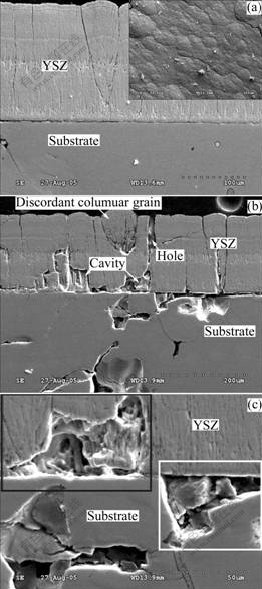
Fig.2 SEM morphologies of cross-section of samples under as- deposited condition: (a) Cross-section and surface morphology of TBC-coated sample after YSZ deposition; (b) Defects in substrate and YSZ after deposition; (c) High-magnification SEM image of defects
Fig.3 shows the cross-sectional images of the specimens after YSZ deposition, 50-cycle oxidation and 100-cycle oxidation. From Fig.3(a), no cavities can be found in the substrate under the YSZ/substrate interface. After 50-cycle test, there exist some cavities along a line about 20 ��m right under the YSZ/substrate interface. The large size of the cavities (diameter of 15 ��m), suggests that more than an alumina phase transformation[13-14] is involved in cavity growth. From element distributions of points A and B (in Fig.2(b)) determined by EDS (in atomic percent, point A: 20.19Al, 79.81Ni; point B:
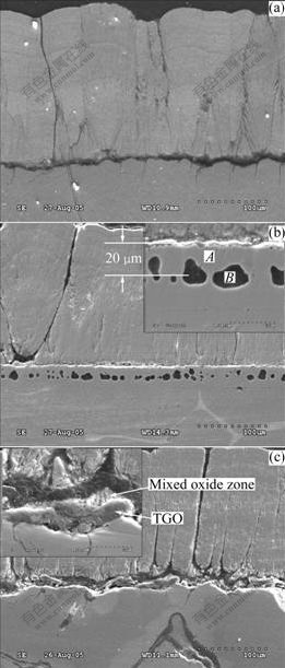
Fig.3 Evolution of cross-sectional morphologies of specimens after cyclic oxidation at 1 200 ��: (a) Flat YSZ/substrate interface after deposition; (b) Voids formation in substrate after 50 cycles; (c) Irregular YSZ/TGO/substrate interface after 100 cycles
45.27Al, 31.02Ni, 23.71O), it is evident that point A is composed of �á�- and ��-phase, while the inner side of the cavities (Point B) is mainly composed of NiAl and Al2O3. The formation of cavities in the NiAl substrate can be attributed to the volumetric changes during high temperature exposure. The volume reduction occurs due to aluminum depletion and the phase transformation changes from the aluminum-rich ��-phase in the bond coat to higher density �á� and then to the solid solution ��-phase via the following two reactions[15]:
3NiAl+3/2O2��Ni3Al+Al2O3
7Ni+4Ni3Al+3NiAl��Ni+7Ni3Al
Hence, internal cavitation is considered as a result of the spatially constrained volume reduction in the substrate at high temperature[15-16], together with the fact that the depletion of Al proceeds not as a uniform front across the substrate, but distributes in different locations at different time[15-16], so the isolated cavities have the chance to form. And the growth of TGO (which primarily grows by outward transport of Al) would have a greater tendency to leave Kirkendall cavities in the substrate near the interface. Kirkendall porosity usually observed in the diffusion zone in ��/�� or ��/(��+��) diffusion couples, may contribute too much to the cavities�� formation[15-17].
After 100 cycles, as shown in Fig.3(c), the cavities shown in Fig.3(b) disappear, while the mixed oxide zone was entangled in the irregular and discontinuous TGO, which is different from the flat and uniform TGO shown in Fig.3(b). Cracks along the mixed oxide zone, along the TGO/substrate interface, and through the broken TGO all can be observed. Linkage and collapse of the cavities[11] shown in Fig.3(b) result in the TGO/ substrate interface proceeding in an upward-downward direction, and then cause the formation of the cracked, ragged and discontinuous TGO. The later-formed TGO (formed after cracking) causes great stress in both YSZ and substrate. In addition, cracks may easily arise along both sides of the TGO as well as in the TGO. As the cracks�� nucleation, propagation and coalescence, the spallation of the coating brings its eventual failure[1, 8, 12].
Fig.4 shows the cavities inside the NiAl substrate after 50-cycle oxidation, and, besides the circular and radial cracks, a hole can also be observed on the inner surface of the cavity. It is believed that the volume reduction, constrained by the surrounding metal, creates local regions of hydrostatic tension in the bond coat, and if the stress is not relaxed, cavities are likely to form[15], together with the formation of cracks and holes that are
the trajectories of the cavity formation. Maybe these cracks or holes provide the fast diffusion route for the oxygen.
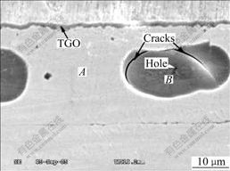
Fig.4 SEM micrograph showing cracks inside cavities of substrate
Fig.5 shows the SEM morphology and EDS elemental maps of O, Al, Ni and Zr of sample after 100 h cyclic oxidation. TGO broke and trapped in the NiAl substrate with some material wrapped inside. Another observation was that the elements of Zr, O and Al (except Ni) were detected from the wrapped area surrounded by the TGO, meaning that the TGO-wrapped material is composed of the mixed oxides of fine YSZ particles in alumina matrix. The wrapped material inside TGO is not as a result of YSZ deposition, even for severe substrate cavity as shown in Fig.2(c) (in the black box), no YSZ flux can be observed in it after deposition. Fig.5(f) illustrates the cross section of the as-deposited sample, indicating that the Al2O3+YSZ mixed oxide zone formed after 100 h cyclic oxidation is obviously different from that after YSZ deposition, in which TGO always consists of a continuous and pure alumina layer between the bond coat and the mixed oxide zone.
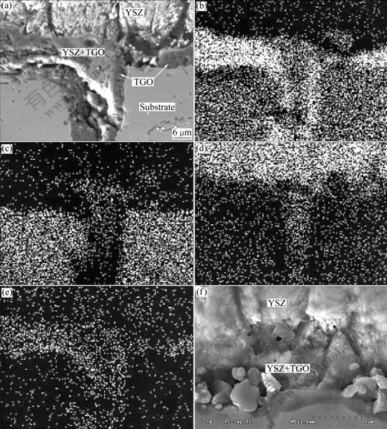
Fig.5 SEM morphology and EDS maps of sample after 100 h cyclic oxidation: (a) SEM morphology; (b) EDS map of element Al; (c) EDS map of element Ni; (d) EDS map of element Zr; (e) EDS map of element O; (f) YSZ+TGO mixed zone formed after YSZ deposition
4 Conclusions
1) There exist cracks or holes in the internal oxidized cavities that can provide the fast diffusion routes or channels for the oxygen.
2) The collapse and closing up of cavities result in the ragged YSZ/TGO/substrate interface��since the specific crack trajectory is quite sensitive to the local geometry, cracks along the YSZ/TGO/substrate interfaces ultimately lead to YSZ spallation.
References
[1] NICHOLLS J R, LAWSON K J, JOHNSTONE A, RICKERBY D S. Methods to reduce the thermal conductivity of EB-PVD TBCs [J]. Surface and Coatings Technology, 2002, 151/152: 383-391.
[2] BENNETT I J, SLOOF W G. The influence of reactive element additions to ��-NiAlCr alloys on the morphology of thermally grown oxides [J]. Materials at High Temperatures, 2003, 20(3): 395-403.
[3] PETERS M, LEYENS C, CHULZ U, KAYSSER W A. EB-PVD thermal barrier coatings for aeroengines and gas turbines [J]. Advanced Engineering Materials, 2001, 3(4): 193-204.
[4] EVANS A G, MUMM D R, HUTCHINSON J W, MEIER G H, Pettit F S. Mechanisms controlling the durability of thermal barrier coatings [J]. Progress in Materials Science, 2001, 46(5): 505-553.
[5] PADTURE N P, GELL M, JORDAN E H. Thermal barrier coatings for gas-turbine engine applications [J]. Science, 2002, 296: 280-284.
[6] HAYNES J A, FERBER M K, PORTER W D. Thermal cycling behavior of plasma-sprayed thermal barrier coatings with various McrAlX bond coats [J]. Journal of Thermal Spray Technology, 2000, 9: 38-48.
[7] NEWAZ G, CHEN X Q. Progressive damage assessment in thermal barrier coatings using thermal wave imaging technique [J]. Surface and Coatings Technology, 2005, 190: 7-14.
[8] LUGHI V, CLARKE D R. Transformation of electron-beam physical vapor-deposited 8wt% yttria-stabilized zirconia thermal barrier coatings [J]. Journal of the American Ceramic Society, 2005, 88: 2552-2558.
[9] PAN D, CHEN M W, WRIGHT P K, HEMKER K J. Evolution of a diffusion aluminide bond coat for thermal barrier coatings during thermal cycling [J]. Acta Materialia, 2003, 51: 2205-2217.
[10] RAGARAJ S, KOKINI K. Interface thermal fracture in functionally graded zirconia-mullite-bond coat alloy thermal barrier coatings [J]. Acta Materialia, 2003, 51(1): 251-267.
[11] WADA K, YAMAGUCHI N, MATSUBARA H. Effect of substrate rotation on texture evolution in ZrO2-4 mol.% Y2O3 layers fabricated by EB-PVD [J]. Surface and Coatings Technology, 2005, 191(2/3): 367-374.
[12] DONG L, SMITH R W, SCROLOVITZ D J. A two-dimensional molecular dynamics simulation of thin film growth by oblique deposition [J]. Journal of Applied Physics, 1996, 80: 5682-5687.
[13] SINGHESISER L, STEINBRECH R, QUADAKKERS W J, HERZOQ R. Failure aspects of thermal barrier coatings [J]. Materials at High Temperatures (UK), 2001, 18(4): 249-259.
[14] HAYNES J A, LANCE M J, PINT B A,WRIGHT I G.Characterization of commercial EB-PVD TBC systems with CVD (Ni, Pt) Al bond coatings [J]. Surface and Coatings Technology, 2001, 146/147: 140-146.
[15] VLADIMIR K, TOLPYGO V K, CLARKE D R. Damage induced by thermal cycling of thermal barrier coatings [J]. TMS Proceeding, 2001, 4: 93-107.
[16] ALI M S, SONG S, XIAO P. Evaluation of degradation of thermal barrier coatings using impedance spectroscopy [J]. Journal of the European Ceramic Society, 2002, 22(1): 101-107.
[17] TOLOPYGO V K, CLARKE D R. Failure mechanisms associated with the thermally grown oxide in plasma-sprayed thermal barrier coatings [J]. Acta Materialia, 2000, 48(15): 3963-3976.
Foundation item: Project(50571005) supported by the National Natural Science Foundation of China
Corresponding author: LI He-fei; Tel: +86-10-82317117; Fax: +86-10-82338200; E-mail: 6182050@sohu.com
