
J. Cent. South Univ. Technol. (2009) 16: 0546-0551
DOI: 10.1007/s11771-009-0091-6
![]()
Die design for cold precision forging of bevel gear based on finite element method
Jin Jun-song(����)1, Xia Ju-chen(�ľ���)1, Wang Xin-yun(������)1, Hu Guo-an(������)1, Liu Hua(�� ��)2
(1. State Key Laboratory of Material Process and Die & Mould Technology,
Huazhong University of Science and Technology, Wuhan 430074, China;
2. Metal Forming Division, Zhengzhou Research Institute of Mechanical Engineering, Zhengzhou 450052, China)
Abstract:
The finite element analysis (FEA) software Ansys was employed to study the stress state of the dies of both plane and non-plane parting face structures with uniform interference and the die of plane parting face structure with non-uniform interference. Considering the symmetry of the die, a half gear tooth model of the two-ring assembled die with 2.5 GPa inner pressure was constructed. Four paths were defined to investigate the stress state at the bottom corner of the die where stress concentration was serious. FEA results show that the change of parting face from non-plane to plane can greatly reduce the stress at the teeth tips of the die so that the tip fracture is avoided. The interference structure of the die is the most important influencing factor for the stress concentration at the bottom corner. When non-uniform interference is adopted the first principal stress at the corner on the defined paths of the die is much lower than that with uniform interference. The bottom hole radius is another important influencing factor for the corner stress concentration. The first principal stress at the corner of the plane parting face die with non-uniform interference is reduced from 2.3 to 1.9 GPa when the hole radius increases from 12.5 to 16.0 mm. The optimization of the die structure increases the life of the die from 100 to 6 000 hits.
Key words:
die; gear; precision forging; finite element analysis; optimized design��
1 Introduction
Differential bevel gears are widely used as component of automobile transmission device. At least, four bevel gears (two half axle gears and two pinions) are used on a car and 6 bevel gears (two half axle gears and four pinions) used on a truck [1].
With the increase of demand on both the quality and the cost of products, cold forging has gradually replaced machining process. Cold forging process has many advantages, such as good surface quality, improved mechanical properties and better dimensional accuracy of the formed products. Especially, closed-die forging for near-net-shape of bevel gears has been well known as an effective process to reduce manufacturing cost of the products [2].
Forming of bevel gears has been studied for years. With the progress of computation technology, computer aided engineering, such as finite element analysis (FEA), and computer aided process planning (CAPP) has been introduced into the metal forming field [3]. KUTUK et al [4-9] studied the closed die forming process by finite element method (FEM). HE et al [10] studied the forming process by experiments. BOCHNIAK et al [11] investigated single warm forging operation on a press with reversibly rotating die. However, the researches mentioned above mainly focused on the forming process with a simple die structure, and the die designed in the researches cannot meet the requirements of large scale production. KANG et al [12] studied the springback of the die in gear forging by FEM, and the compensation for the springback was made in die machining to increase the accuracy of the gears. KAWASAKI and SHINMA [13] manufactured dies by numerical control (NC) milling instead of electric discharge machining to increase the accuracy of dies. FU and SHANG [14] analyzed the stress state and optimized the rings radius of the assembled dies for bevel gear forging by boundary-element method. In this work, the tool failure in gear forging by FEA was investigated, and the die structure was optimized.
2 Die structure and failure mode
2.1 Experimental conditions
The part in the experiment is a 16 teeth bevel gear with 3.869 mm module, 61.904 mm pitch diameter and 24? pressure angle. The gear has 57.995? pitch cone angle, 50.734? root cone angel and 63.317? tip cone
angle. The addendum, dedendum, back sphere diameter and circular tooth thickness at the big end of the bevel gear are 2.850, 4.640, 76.850 and 5.693 mm, respectively. The billet material used to form the gear is 20CrMo. It is annealed at 770 �� to a hardness of HB140. The cylindrical billet is 32 mm in diameter, and 37 mm in height. Surface phosphate treatment is employed, and MoS2-oil mixture is used for better lubrication. The die is made of 65Nb Steel. The die cavity is machined by high-speed milling, and polished to the roughness of 0.2 ��m. After heat treatment, the hardness of the die is HRC58. Forging is carried on a Y-28-400/400 double action hydraulic press. The die structure is illustrated in Fig.1. Because of the heavy forming load and clamping force, the die is easily led to failure so that two-layer assembled die structure is employed, in which 0.4 mm interference between the shrink ring and the insert of the die is adopted [15]. In the experiment, 3.0 MN clamping force is applied on the die.
2.2 Parting face design and failure mode
To get net shaped gear teeth, the die is initially designed to a non-plane parting face structure as shown in Fig.2(a) (die��). However, the tooth tip of the die is fractured after about 100 hits ( Fig.3(a)). As a trial design, a plane parting face, as shown in Fig.2(b) (die ��), is employed. But the situation is not much improved, and crack occurs at the bottom corner of the die after about 600 hits, as shown in Fig.3(b).
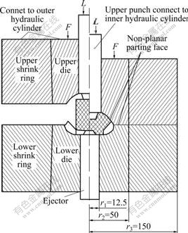
Fig.1 Gear forging die structure (Unit: mm)
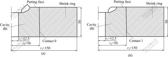
Fig.2 Assembled die with uniform interference (Unit: mm): (a) Die��, non-plane parting face die; (b) Die ��, plane parting face die
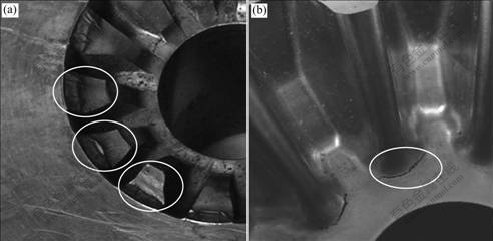
Fig.3 Failure modes of die: (a) Tip fracture; (b) Bottom corner crack
2.3 Assembled die structure design and failure mode
Conventionally, in an assembled die set, the insert usually has the same height as the shrink rings, and uniform interference at the matching interface is employed [16-17]. The cold closed forging gear dies with uniform interference fit are shown in fig.2. In the common assembled die design, the die structure is simplified as thick-wall cylinders for calculation [18-19]. The design is based on the assumption of infinite length thick-wall cylinder with uniform inner pressure. Generally, this method is suitable for the assembled die design of backward extrusion and forward extrusion because the boundary conditions of the dies are coincident with the thick-wall cylinder assumption. But it is not feasible for die with a non-uniform cavity and thick bottom, such as the die of bevel gear cold forging, because the boundary condition is far away from the assumption of the thick-wall cylinder, and the stress concentration in the cavity is serious.
For the dies with thick bottom, two methods may be tried to cope with the problem. One is to increase the radius at the corner to reduce stress concentration. This method contributes little to the resolution of the problem because the dimension change of the precision formed part is unallowable. The other one is to increase the pre-stress between the rings of the die which needs a bigger interference. However, this approach is limited by the admissible stress of the die material. Furthermore, too big interference will lead to the difficulty in die assembly. Especially for the complex gear cavity of the gear die studied in this work, excessive interference will lower the accuracy of the formed part, and contribute little to die life elongation. Therefore, assembled die structure with non-uniform interference is adopted in this work, as shown in Fig.4 (die ��). Appropriate interference is applied to the cavity part, and very small interference is used for the thick bottom part. But after 1 200 hits, crack occurs again, as shown in Fig.3(b).
3 FEA model
The FEA of the gear die is carried out with Ansys
software. Because of the high hardness and small temperature variation, the die is considered as an elastic body in FEA. The die material has hardness of HRc 58 and tensile strength of 2.538 GPa. The elastic modulus of the material is 207 GPa, and its Poisson ratio is 0.292. To compare the stress distribution, models of die��, die�� and die ��, shown in Figs.2 and 4, are constructed.
In the forging process, the load reaches the maximum value when the die is fully filled. Forming process simulation is performed by DEFORM software. The predicted clamping force is 2.83 MN so that 3 MN clamping force is exerted in the experiment. Because forming process and die stress are analysed by different softwares, the final reaction forces on the nodes in contact area obtained by forming process analysis could not be directly used as the boundary conditions for die stress analysis, and need to be transformed for die analysis. In accordance with FEA results of forming process analysis, the material does not flow in the cavity at the final filling stage except for the tooth tip corner region. The pressure is around 2.5 GPa, and distributes on the cavity surface uniformly. On the tooth tip surface, there is a friction force along the material flow direction, and the friction coefficient is 0.12.
The matching pair locations in the die structures are defined, as shown in figs.2 and 4. 0.4 mm interference is taken for the matching pairs 0, 1 and 2. And all the matching pairs are defined as face to face type. A contact face and a target face are included in each matching pair, and defined by contact-170 element and contact-174 element, respectively. The contact definition is very important in the analysis because it has decisive effect on the accuracy and cost of computation. In comparison with other matching type, face to face matching pair has advantages, such as supporting both lower order and higher order elements, suitable for complex contact surface, smaller storage space and short CPU time needed [20].
To reduce the simulation time and obtain more accurate results, a half tooth model is built, and the symmetry boundary condition is applied (fig.5). And
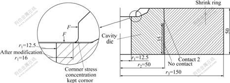
Fig.4 Schematic diagram of Die ��: Plane parting face die with non-uniform interference and modification of bottom hole radii (Unit: mm)
mixed-mesh is adopted to discretize the model. Brick-186 element is employed to mesh regular solid by sweep method. In non-regular cavity, brick-186 element is degenerated to tetrahedral element to fit the complex cavity body, and tower element is generated between tetrahedral element and brick element. Then, the degenerated tetrahedral element-186 is changed to tetrahedral element-187 which has high calculation efficiency.
4 FEA results
The effective stress and the first principal stress distribution on tooth tip of die �� and die �� are shown in Fig.6.
To investigate the stress distribution at the bottom corner, path tool of the FEA software is utilized. This tool is capable of outputting the variable values, such as stress, strain and displacement, on predefined paths (Fig.5). In Fig.7, effective stress and the first principal stress on the four paths on the tooth tip of die �� and die �� are illustrated.
5 Analysis results discussion and application to die design
As shown in Fig.6, serious stress concentration occurs in non-plane parting face die structure. The maximum of effective stress and the first principal stress reach 5.25 and 3.20 GPa at the tooth tips, respectively, which greatly exceed the allowable stress of the die material. That is why tip fracture occurs during forging process. The maximum effective stress and the first principal stress in die �� are 2.0 and -0.6 GPa, respectively. Compared with those of die ��, the maximum effective stress of die �� decreases by 60%,
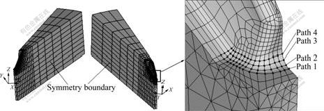
Fig.5 FEA model with symmetry boundary and four defined paths
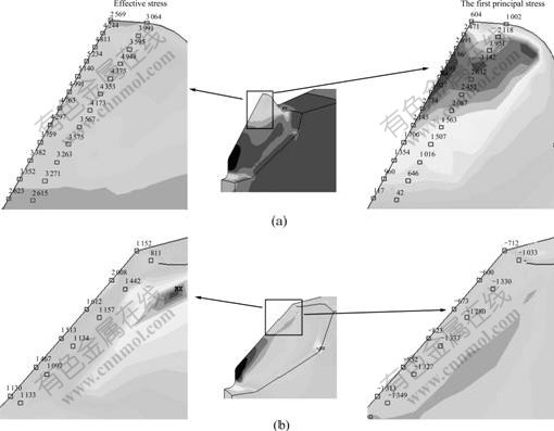
Fig.6 Effective stress and the first principal stress distribution on tooth tip: (a) Die ��; (b) Die ��(Unit: MPa)
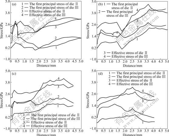
Fig.7 Stress distribution on four predefined paths: (a) Path 1; (b) Path 2; (c) Path 3; (d) Path 4
and the first principal stress of die �� changes from tensile one to compressive one.
From Fig.7(a), it can be seen that the effective stress and the first principal stress reach 2.9 and 2.6 GPa respectively at the distance of 0.3 mm on path 1 of die ��. The first principal stress exceeds the tensile strength. In die ��, the first principal stress at the same location is lower than 800 MPa. This means that the stress reduction ratio reaches 69%. According to Fig.7(b), both the effective stress and the first principle stress at distance of 1.8 mm on path 2 of the two dies begin to increase quickly, and reach the maximum at the distance of 3.7 mm on path 2. The first principal stress reaches 2.7 GPa in die ��, which exceeds the tensile strength. And the maximum principal stress reaches 2.3 GPa in die ��, which is only 238 MPa lower than the tensile strength of the die material. This means that the failure is likely to occur at this point in die ��. In fact, the crack occurs after about 1 200 hits in the experiment. According to Fig.7(c), the first principal stress on path 3 in die �� is at least 28.5% lower than that in die ��. And the first principal stresses in both of the dies are lower than the tensile strength of the die material. At the distance of 2 mm from the left end, the effective stress in die �� is greater than that in die ��. Fig.7(d) shows that both the first principal stress and effective stress on path 4 in die �� and die �� are much lower than the allowable stress of the die material.
During forging process, the bottom and the vertical wall of the die bear high pressure, and the forces acting on the two regions of the die are perpendicular to each other, which leads to a serious stress concentration at the corner (fig.4). This is the reason for the high first principal stress on path 2 of die ��. To reduce the stress, an effective measure is to enlarge the bottom hole radius r1. However, the enlargement of r1 is limited by the round fillet on the gear shown in Fig.4 which should be formed in the forging process, otherwise, it is difficult to machine in later processing. The hole radius r1 in the non-uniform interference die structure could only be enlarged to 16 mm (die ��).
Fig.8 shows the stress distribution on the four paths in die �� with the same boundary condition as in die ��. All the stresses on the four paths decrease. Especially, the maximum of the first principal stress on path 2 reduces from 2.3 to 1.9 GPa. As a result, the life of the die increases from 1 200 to 6 000 hits, that is, the die life is five times as large as that of the original die.
In production practice, it is time-consuming to develop a die for forming a new gear part. The trial and error method usually take 30-40 d to accomplish the die development. In contrast, only a week is enough to design the same die based on FEA result.
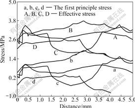
Fig.8 stress distribution on four paths in die ��: a, A��Path 1; b, B��Path 2; c, C��Path 3; d, D��Path 4
6 Conclusions
(1) The change of parting face from non-plane one to plane one can remarkably decrease the effective stress at the tooth tip of the forging die. Accordingly, the stress state on tooth tips changes from tensile one to compressive one so that tooth tips fracture is avoided.
(2) Applying interference only to the cavity region in the plane parting face die, instead of applying it to the whole height of the die, can effectively increase the pre-stress on the cavity region of the die. Stress concentration at the corner is greatly relieved so that the die life increases from 600 to 1 200 hits.
(3) By enlarging the bottom hole of the non-uniform interference die from 12.5 to 16.0 mm, the stress at the die corner reduces from 2.3 to 1.9 GPa. Consequently, the die life is elongated from 1 200 to 6 000 hits, and the requirement of mass production is satisfied.
References
[1] Rong Hua-wei. The autos quantity in China will become the world-first in 2010 [J]. Market Weekly (New Logistics), 2007(7): 49-49. (in Chinese)
[2] Wang Xin-yun, Xia Ju-chen, Hu Guo-an. Numerical forming of car bevel gears [J]. Metal Forming Technology, 2005, 30: 58-61. (in Chinese)
[3] Shuai Ci-jun, Xiao Gang, Ni Zheng-shun, Zhong jue. Application of computer-aided engineering optimum design method in aluminum profile extrusion mould [J]. Journal of Central South University of Technology, 2002, 10(1): 64-68.
[4] KUTUK M A, EYERCIOGLU O, YILDIRIM N, AKPOLAT A. Finite element analysis of a cylindrical approach for shrink-fit precision gear forging dies [J]. Journal of Mechanical Engineering Science, 2003, 217(6): 677-685.
[5] YOON J H, YANG D Y. A three-dimensional rigid-plastic finite element analysis of bevel gear forging by using a remeshing technique [J]. International Journal of Mechanical Sciences, 1990, 32(4): 277-291.
[6] ZHANG Y Z, HUANG J B, LIN X, FANG Q S. Numerical simulation analysis on cold closed-die forging of differential satellite gear in car [J]. Materials Science Forum, 2008, 575-578 Part 1: 517-524.
[7] MARKUS M, MARKUS K, KNUT W, TAYLAN A. Numerical and physical modelling of cold forging of bevel gears [J]. Journal of Materials Processing Technology, 1992, 33(1/2): 75-93.
[8] SONG J H, IM Y T. Process design for closed-die forging of bevel gear by finite element analyses [J]. Journal of Materials Processing Technology, 2007, 192/193: 1-7.
[9] MAMALIS A G, MANOLAKOS D E, BALDOUKAS A K. Simulation of the precision forging of bevel gears using implicit and explicit FE techniques [J]. Journal of Materials Processing Technology, 1996, 57(1/2): 164-171.
[10] He Chang-qing, Xia Ju-chen, Wang Xin-yun, HU Guo-an, WU Zhong-min, CHEN Xia. Experimental study on precision cold forging for bevel gear used in car [J]. China Metalforming Equipment and Manufacturing Technology, 2005, 40(2): 65-67. (in Chinese)
[11] BOCHNIAK W, KORBEL A, SZYNDLER R, HANARZ R, STALONY-DOBRZA?SKI F, BLA? L, SNARSKI P. New forging method of bevel gears from structural steel [J]. Journal of Materials Processing Technology, 2006, 173: 75-83.
[12] KANG J H, LEE K O, KANG S S. New forging tool manufacturing method for spur gear part [J]. Journal of Engineering Manufacture, 2007,221(11): 1601-1606.
[13] KAWASAKI K, SHINMA K. Design and manufacture of straight bevel gear for precision forging die by direct milling [J]. Machining Science and Technology, 2008, 12(2): 170-182.
[14] Fu Ming-wang, Shang Bao-zhong. Stress analysis of the precision forging die for a bevel gear and its optimal design using the boundary-element method [J]. Journal of Materials Processing Technology, 1995, 53(3/4): 511-520.
[15] WU S C. Cold and warm extrusion technology [M]. Beijing: National Defense Industry Press, 1995. (in Chinese)
[16] Liu Xiao-bo, Tan Jiang-ping, Yi You-ping. Stress filed analysis of extra-height forging die using finite element method [J]. Journal of Central South University of Technology, 1999, 6(1): 59-62.
[17] YOH E G, KIM Y I, LEE Y S, PARK H A, NA K H. Integrated analysis for die design including brittle damage evolution [J]. Journal of Materials Processing Technology,2002, 130/131: 647-652.
[18] Zhang Hui, Sun Wei. Optimum design of combined extrusion female dies [J]. Forging and Stamping Technology, 2005, 30(4): 61-63. (in Chinese)
[19] Xu Xiao-bin. The optimum design on three-layer assembled cavity die of cold extrusion [J]. Metal Forming Technology, 2003, 21(3): 59-62. (in Chinese)
[20] SHENG Yong-hua, WANG Xin-yun, JIN Jun-song, XIA Ju-chen. Application of Ansys in assembled cavity die stress analysis [J]. Die and Mould Technology, 2005(2): 47-50. (in Chinese)
(Edited by YANG You-ping)
Foundation item: Project(2006BAF04B06) supported by the National Key Technology R & D Program of China; Project(2005AA101B19) supported by the Key Technology R & D Program of Hubei Province, China
Received date: 2008-08-16; Accepted date: 2009-02-16
Corresponding author: WANG Xin-yun, Associate professor, PhD; Tel: +86-27-87543491; E-mail: wangxy_hust@163.com
