
Trans. Nonferrous Met. Soc. China 28(2018) 2062-2074
Pressure distributions generated by vaporizing metal foils
Sheng CAI
Department of Vehicle Engineering, College of Engineering, China Agricultural University, Beijing 100083, China
Received 19 June 2017; accepted 23 November 2017
Abstract:
The pressure distributions generated by vaporizing metal foils were studied. An analytical model which described the dynamic mechanical behavior of a rectangular plate under an impulsive loading was introduced. The formed parts of free bulging tests were analyzed using the optical measurement system. Two measurement methods for pressure distributions were introduced and compared. Both the perforated sheet forming test and the pressure film were found to be effective method to measure pressure distributions. The cost of perforated sheet forming test was cheap and the pressure film was easy to operate. Three different pressure distributions were measured and discussed, namely single pressure distribution, tailored pressure distribution and double-direction pressure distribution. These three pressure distributions could be applied in different metal forming processes.
Key words:
pressure distribution; vaporizing foils; sheet metals; impulse forming;
1 Introduction
In order to reduce the exhaust of CO2 and maintain the vehicle performance, more environmentally friendly designs in automotive industries must include the lightweight construction of the car and an increase of functionality of the components. The general problems brought by the new challenges are the increasing geometrical complexity of the components and a requirement for a higher forming limit of the material.
A general solution for the new challenges could be the impulsive forming method. Applying impulsive forming methods, forming limits can be extended to higher value as well as spring-back and cost of tools can be reduced, compared to quasi static forming methods [1]. Using tensile�Ctensile fatigue testing, the effect of electromagnetic bulging on the fatigue behavior of the 5052 aluminum alloy was investigated. The bulged parts displayed improved fatigue strength by comparison with original aluminum alloys [2]. A modeling of stresses and strains in electromagnetically deformed AlMn0.5Mg0.5 sheet was achieved using the finite element method. A good agreement between the modeling results and experimental data was obtained. The rapid vaporization of thin metallic conductors can be used for innovative high speed forming processes [3]. Vaporizing metal foils were employed to accelerate thin plates [4]. It is found that vaporizing foils is a feasible approach to accelerate thin plates to high velocities. A technique to accelerate thin plate by means of vaporizing foils was developed [5]. The flyer velocities up to 5000 m/s were measured. The technique of vaporizing thin conductors like metal wire or foils was applied to metal forming processes [6,7]. Different metal processing applications including shearing, tube expanding, collision welding and embossing are experimentally identified. Firstly, 0.5 mm-thick pure titanium sheets (yield strength 345 MPa, tensile strength 486 MPa) are formed into a cell phone case die (see Fig. 1). Aluminum foils with 50.8 mm-long and 12.7 mm-wide active sections are employed as actuators.
Vaporizing thin conductors is a feasible technique to conduct metal forming process. This forming method is essentially an impulsive forming process and thereafter owns the general advantages of impulsive forming including the improved forming limit and reduced springback. This process could be an alternative process for the electromagnetic forming to avoid the problems including the expensive tool coils and high requirement for the electrical conductivity of the workpiece. In order to improve the understanding of this process, the pressure distributions need to be investigated to apply this technique in metal forming process. The measurement techniques for the indication of shock pressure distribution will be presented. Finally, three different pressure distributions are discussed, namely single pressure distribution, tailored pressure distribution and double-direction pressure distribution.
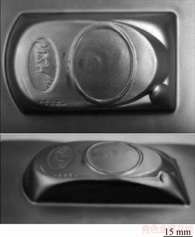
Fig. 1 CP titanium sheet formed by hybrid forming technique at input energy of 6.4 kJ
2 Experimental
The experiments in this work were conducted on two different capacitor banks. The first machine is a Maxwell capacitor bank with a maximum charging energy of 32 kJ and a relatively long current rise time of 8.9 ��s. The second machine is a SMU capacitor bank with a maximum charging energy of 9 kJ and a relatively short current rise time of 2.7 ��s. The parameters of the two capacitor machines are listed in Table 1.
The polyurethane plate in the forming process actuated by vaporizing foils can be employed to improve the spread of the pressure area on the workpiece [8,9]. Two polyurethane plates with thicknesses of 7 mm and 10 mm were applied to identifying the thickness effect. The properties of the polyurethane plates are presented in Table 2.
2.1 Perforated sheet forming test
A perforated plate was positioned on the top of the workpiece. When the shock wave impacted on the workpiece, the material flows upwards and then is blocked by the perforated plate. There is a shearing process on the workpiece within the shock impact area. The workpiece is formed to be with many small bulges or even sheared out to be with many small holes dependent on the shock pressure amplitude. Therefore, the shock impact area can be observed directly through the formed bulges or sheared holes. The pressure distribution is indicated with a rectangular frame which is similar to the shape of the active area of the foil specimen. Therefore, the pressure area could be measured.
Table 1 Capacitor bank characteristics
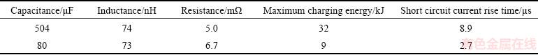
Table 2 Properties of polyurethane plate

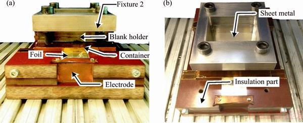
Fig. 2 Experimental setup
The process principle of the perforated sheet forming test is shown in Fig. 3. The perforated plate is made of steel with a thickness of 20 mm. The holes on the perforated plate are in a diameter of 3 mm. The high density of the holes over the perforated plate guarantees an actuate measurement of the pressure distribution. Based on the fact that the pressure area is indicated by the deformation of the workpiece, pure aluminum sheet is employed as the workpiece due to its relatively low flow stress. An example part formed by perforated forming test is revealed in Fig. 3 as well.
2.2 Determination of pressure distribution by pressure film
A pressure sensitive film was applied to measuring the compressive pressure during uniaxial compression test [10]. This film has many microcapsules which contain the color-forming material and color-developing material. When the film is subjected to pressure, the microcapsules are broken and these two materials react with each other to generate color. Because the microcapsules are designed to react according to the level of pressure, the color density can indicate the level of pressure. The entire pressure film functions as a sensor and the whole pressure distribution on it can be observed at a glance.
The structure of the pressure film is illustrated in Fig. 4. For the mono-sheet type, the color-developing material is coated on a polyester base, with the micro- encapsulated color-forming material layered on top. When the pressure is applied, the microcapsules are broken and the color-forming material reacts with the color-developing material. Red patches appear on the film. In this work, the Fuji film is employed to measure the pressure distribution of the double-direction pressure distribution. The advantage of this measurement technique for pressure distribution compared to perforated sheet forming test is the easy handling as well as the direct visuality. For example, the perforated sheet is expected to be designed with a large density of small holes in order to acquire a actuate measurement of pressure area. This results in a long machining time for the manufacturing of the perforated sheet. In the case of a complex metal forming process, the handling for the perforated sheet is also a problem for its application. On the other hand, the Fuji film is very expensive while the perforated test has a relatively low cost because the perforated sheet can be repeated for many operations. Considering the experiment cost and feasibility of the measurement of pressure distribution under different conditions, the perforated sheet test is used to measure the single pressure distribution and tailored pressure distribution while the Fuji film is applied for the measurement of double-direction pressure distribution. An example case of Fuji film measurement result is presented in Fig. 4 as well.
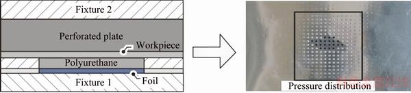
Fig. 3 Principle of perforated sheet forming test and its example part
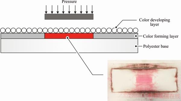
Fig. 4 Principle of pressure film and example of pressure distribution measurement
3 Dynamic mechanical behavior of sheet metal under impulsive loading
In order to improve the understanding of the high speed forming process by vaporizing foils and provide guidance for a sufficient process design, the analysis of the dynamic behavior of the sheet metal under impulsive loading is introduced. The total energy of the dynamic loads is sufficient to cause plastic flow of the plate material.
Figure 5 describes a measured pressure curve induced by vaporizing foils. The most significant pressure values are the amplitude of the function (pm) and the so-called collapse load (py) [11]. At this pressure the plastic deformation is triggered if the acting shock pressure pm exceeds the value of py. The pressure pulse can be in different shapes such as the rectangular, linear decay, exponential decay, triangular. As shown in Fig. 5, the shock pressure generated by vaporizing foils is in a general shape. In order to simplify the analysis process, the pressure pulse is assumed as a quadratic sinusoidal function which has the same amplitude with the actual case. The period of the quadratic sinusoidal function is determined by the durance of the actual pressure pulse.
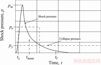
Fig. 5 Schematic diagram of shock pressure curve
The effect of pulse shape on final plastic deformation was examined [12]. There is a strong dependence on pulse shape for pulses which have the same total impulse and maximum load. But the effect of the pulse shape is virtually eliminated if the pulses have the same total impulse and the so-called effective load. With this method, the actual pressure pulse in arbitrary shape can be transferred into an equivalent rectangular pulse since the pulse in rectangular shape is the simplest case for analysis of the dynamic plastic response determination of a structure. For the transformation, HODGE [12] developed three characteristic parameters for pressure pulse. If these parameters are equal for different pressure functions, the deflection resulting from these pulses is equal as well. The first of these parameters is the total impulse (I), which is defined as the integral of the pressure function from the beginning of the plastic deformation tc to its end tf.
 (1)
(1)
The second parameter is the effective pressure pe. This specific value corresponds to the pressure magnitude of a rectangular pulse with the same total impulse as the treated pressure function acting for two times the tmean.
 (2)
(2)
The tmean is defined as the interval between the onset of the plastic deformation and the centroid of the pressure pulse.
 (3)
(3)
The dynamic plastic behavior of a simply supported square plate was examined which is subjected to a rectangular pressure pulse distributed uniformly over the entire surface area [13]. In order to simplify the analysis, the simple square yield criterion and a rigid, ideal plastic material model for the workpiece were employed. The yielding surface can be represented in a two-dimensional principle moment space as shown in Fig. 6 for the square and Tresca yield criteria. Here, M1 and M2 are the principle bending moments and M0 is the maximum moment which triggers the plastic movement of the material. In a rectangular plate, the principle bending moments are related to the moments Mx, My and Mxy Mxy, which are defined in Fig. 6, as follows:
 (4)
(4)
Therefore, the material flow in the plastic hinges of the plate is controlled by the regime AB of the square yield condition, which is
 (5)
(5)
It is assumed that the transverse velocity field of a rectangular plate has the same form as the static plastic collapse profile. As shown in Fig. 7, the velocity (v) of the workpiece at different positions can be expressed as
 (6)
(6)
In regions 1 and 2,
v=V(B-y)/B (7)
where V is the maximum transverse velocity at the plate center, B and L are respectively the semi-width and semi-length of the plate and ��=B/L. As a result, regions 1 and 2 are rigid and all plastic flow of the plate only occurs in the plastic hinges located at the boundaries of the regions.
The maximum permanent deflection (��f) of a rigid, perfectly plastic continuum with a time-independent density, subjected to an initial velocity field can be obtained as follows [15]:
 (8)
(8)
where �� and H are the density and thickness of the rectangular plate, respectively.
A rectangular pressure pulse is seen as an impulsive loading when p0/pc ��1. According to the demand of the conservation of linear momentum at t=0, the following equation is given:
p0t0=��v0 (9)
which relates the initial impulsive velocity distributed uniformly over the whole plate with the impulsive loading. In the analysis above, the pressure pulse is in a rectangular form. However, the actual shock pressure induced by vaporizing foils is a general pressure pulse which can be expressed approximately as a sinusoidal function. In this circumstance, the general pressure pulse could be converted into the rectangular case, in which the effective pressure pe can be treated as the initial rectangular impulsive loading p0 discussed above.
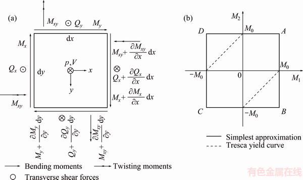
Fig. 6 Loads and moments on plate element (a) and yield domains (b) [14]
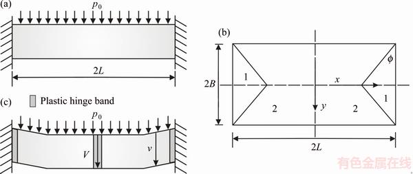
Fig. 7 Geometrical assumptions for collapse pressure determination in side view (a), plane view of square plate (b) and transverse velocity profile (c)
4 Analysis of free forming part
The free bulging test is applied to analyzing the forming behavior of sheet metal by vaporizing foils. The Mises strain distribution of the forming part is measured by GOM Argus optical system and is shown in Fig. 8. The experiment is conducted under the charging energy of 4.8 kJ. The utilized foil has thickness of 0.06 mm and width of 20 mm. The thickness of the polyurethane plate is 10 mm. The largest Mises strain is located at the boundaries and the bulging edges of the part where the plastic hinges are located. When the strain exceeds the forming limit of the material, the crack appears at the boundaries and starts from the corner of the part as shown in Fig. 8. The center part of the sheet metal which corresponds to the active area of the foil specimen also shows large plastic strain due to the shock compression effect. The variation of thickness of the forming part is also measured as shown in Fig. 9. The thicknesses of the center area and the bulging edges are decreased while the thicknesses of the steep walls vary very little or remain constant. At the position closer to the boundaries of the part, the thinning effect becomes weaker. Figure 9 also presents the measured major and minor strains of the whole part. The same color areas correspond to each other. At different areas of the part, the corresponding strain paths are also different. At the center area and the bulging edges of the part, the strain ratio �� ranges from -1 to 1. This explains why the thicknesses at these areas are decreased after the process. At the loading area, �� is close to 1 which means that the thinning effect is more serious at this area due to the equal biaxial stretching. The yellow area with ��=-1 and the green area with ��<-1 correspond to the steep walls of the part. Because the membrane stresses and strains are equal and opposite, the sheet metal deforms without change in thickness. At the positions close to the boundaries, the thickening effect appears (�� <-1).
5 Single pressure distribution
The foil specimen has only one active area in the middle with a length from 50 to 300 mm. The perforated sheet test is employed here to measure the shock pressure area. Considering the specific size of the active area of the foil specimen, two charging energies of 5 and 6 kJ are chosen. The foils in various lengths from 50 to 175 mm are completely vaporized under the charging energy of 5 kJ. Figure 10 presents the pressure distributions measured by perforated sheet forming test.
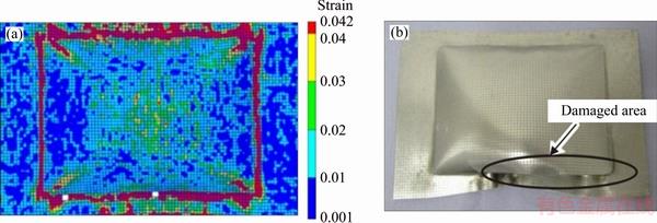
Fig. 8 von Mises strain distribution of forming part (a) and cracked part (b)

Fig. 9 Thickness distribution (a) and major-minor strain diagram of forming part (b)
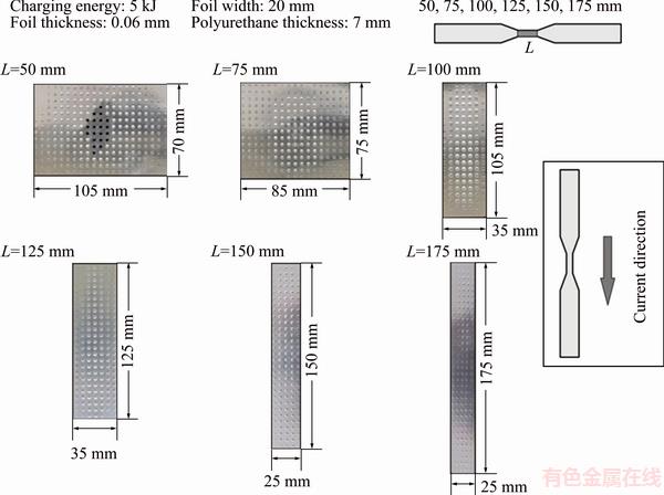
Fig. 10 Pressure distribution with regard of foil length from 50 to 175 mm
When the vaporized area of the foil specimen is 50 mm in length, the induced shock pressure is large enough to shear out the workpiece in the middle. The reduced deformation can be attributed to the weakened shock pressure. The pressure distribution in the case of foil with vaporized length of 50 mm and width of 20 mm is greatly expanded in the transverse direction. The generated pressure area can reach 70 mm in length and 105 mm in width. When the foil length is increased to 70 mm, the final pressure area is in a length of 75 mm and in a width of 85 mm. Also, the foil specimen in a length of 100 mm results in a pressure distribution within a range of 105 mm in length and 35 mm in width. The pressure distributions generated by foil specimen from 125 to 175 mm in length are also shown in Fig. 10.
It can be concluded that all the pressure areas are approximately the same as the active areas of the foil specimens. The length of the pressure distribution is mainly determined by the length of the tailored area of the foil specimen. The pressure distribution can be expanded in the transverse direction when the charging energy is large enough with regard to the vaporized volume of the metal foil, for example, in the case of 5 kJ to vaporize 50 mm-long foil. The vaporized metal gas or plasma spreads greatly sidewards with high pressure and generates a larger pressure area which has a greater width than the foil specimen.
For example, the foil specimen with a width of 20 mm can result in a 105 mm-wide pressure zone which is 5 times of the width of the original foil specimen. When the vaporized volume of the foil is gradually increased, the relative ratio of charging energy to foil volume gets smaller. At this time, the vaporized metal gas or plasma is in a relatively less active state which can be displayed through the temperature of it. The effect of the change in plasma temperature can be observed through the burning effect after the experiment. Although the metal gas or plasma travels also in the transverse direction, the pressure amplitude is not sufficient to generate deformations of the workpiece. Therefore, the width of the pressure area is the same as that of the foil specimen.
The longer foil specimens with an active length until to 300 mm are further investigated and a charging energy of 6 kJ is chosen for the foil specimens. The pressure distributions measured using the perforated sheet forming tests are presented in Fig. 11. The pressure areas have almost the same size with the vaporized area of the corresponding foil specimens. In the case of 300 mm-long foil specimen, the workpiece formed by the perforated sheet forming test displays small deformations. This fact demonstrates the previous result that the shock pressure distribution is determined by the vaporized area of the foil specimen. The charging energy of 6 kJ is not the ideal energy to vaporize metal foil in a length of 300 mm. For a longer foil, a larger electrical charging energy is required.
6 Tailored pressure distribution
The rebound effect in impulsive forming is induced by the inappropriate pressure distributions relative to the workpiece deformations. For example, the uniform pressure distribution is not proper in the manufacturing of parts with different forming depths. In order to reduce the rebound effect in impulsive forming, a pressure distribution with different amplitudes at different positions is required. Tailored pressure distributions by vaporizing tailored metal foils can provide appropriate pressure amplitudes with regard to the corresponding deformation of the workpiece at separate positions [16]. The conformation between the pressure and deformation can thereafter improve the forming accuracy.
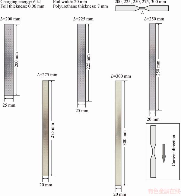
Fig. 11 Pressure distribution with regard of foil length from 200 to 300 mm
The tailored foil can be considered as the normal foil whose cut area in the middle is divided into two discrete parts which can be thereafter treated as two separate single foils. After the discharge of the capacitor bank, the current passes through the whole foil and heats the two separate parts at the same time. The two separate parts compete with each other to absorb the electrical energy from the circuit. The tailored pressure distribution is examined by means of perforated sheet forming test.
This study is conducted experimentally using a capacitor bank with a maximum charging energy of 9 kJ and a short circuit current rise time of 2.7 ��s (see Table 2). The charging energy is set as 5 kJ and the aluminum foil with thickness 0.06 mm is chosen for all the experiments. The foil specimen is tailored at two separate positions where the vaporization happens after the discharge of the capacitor bank.
In order to acquire a significant variation of the workpiece deformation under different process parameters, aluminum alloy EN-AW1050 sheet with thickness of 1 mm is chosen as the workpiece due to its small yielding strength. In order to demonstrate the tailored pressure distribution, a set of perforated sheet forming tests are performed (see Fig. 12). Pure aluminum sheet (99.9%) with thickness of 1 mm is used as the workpiece. The perforated plate is made of steel with thickness of 20 mm. The holes on the perforated plate are 3 mm in diameter. The interval distance between the neighbor holes is 5 mm. The workpieces are 410 mm in length and 190 mm in width.
6.1 Different active lengths at two positions
The geometry of the foils is kept the same for all specimens with length 30 mm at two vaporized positions. The charging energies are chosen as 4, 5 and 6 kJ to examine their effect on the pressure distribution. The pressure area is indicated by the bulged points on the sheet after the perforating forming process. Figure 13 shows that the length of the pressure areas is close to that of the vaporized parts of the foil. With increasing the charging energy of capacitor bank, the width of the pressure areas is enlarged. The pressure amplitude is also improved under larger charging energies, which can be reflected from the large bulging heights of points or sheared holes. Subsequently, the lengths of the vaporized areas at two positions are varied which are 30, 60 and 90 mm, respectively. The lengths of two vaporized parts of a specimen are kept at the same with each other. The charging energy of capacitor bank is chosen as 5 kJ for all the specimens. All the tailored foils are fully vaporized even when the length of the vaporized part is increased to 90 mm (180 mm vaporized in total).
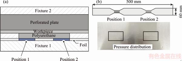
Fig. 12 Principle of measurement for tailored pressure distribution
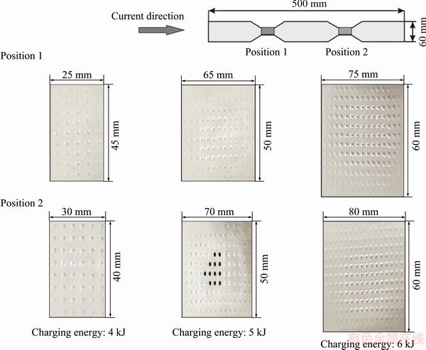
Fig. 13 Perforating formed sheets with respect to different charging energies
As shown in Fig. 14, the pressure area on the perforating formed sheet in the case of tailored length of 90 mm is almost the same with the dimension of the vaporized part of the foil. With regard to the tailored length of 30 mm, the pressure area on the perforating formed sheet is extended in the transverse direction. For example, the width of the pressure area in the case of tailored length of 30 mm is 68 mm while the width of the pressure area induced by vaporizing foil specimen with tailored length of 90 mm is reduced to 28 mm.
The reason can be attributed to the increased vaporized volume of the foil. In this case, the vaporized volumes for three different specimens are 72, 144 and 216 mm3. Under the same charging energy, the deposited electric energy density is reversely proportional to the vaporized volume of the foil specimen. Therefore, the shock pressure amplitude induced by vaporized shorter foil is improved compared to that induced by longer foil.
6.2 Different active lengths at one position
In this part the lengths of the vaporized areas are only changed at one vaporized position while the lengths of the vaporized area at the other position are kept constant. The changed lengths at one position are chosen as 30 and 50 mm and the constant length at the other position is chosen as 90 mm. The initial charging energy of capacitor bank is used as 5 kJ.
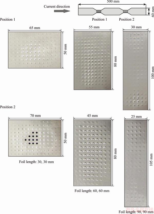
Fig. 14 Perforating formed sheets with respect to different vaporized lengths at two tailored positions
All the tailored parts of the foils are totally vaporized after the discharge of the capacitor bank. Figure 15 shows that the lengths of the pressure area are determined by the separated vaporized parts of the foils. For example, the position with tailored length of 30 mm results in a shorter but wider pressure area (45 mm long and 55 mm wide). The pressure area on the other side generated by means of tailored length of 90 mm possesses a greater length of 100 mm but a smaller width of 35 mm. Due to the different dimensions of the two tailored parts in a specimen, the pressure areas corresponding to the two positions are various as well.
It can be concluded that for a foil specimen with different vaporized lengths but with the same thickness and width, the longer side can absorb more electrical energy form the circuit and thereafter lead to larger shock pressure amplitude as well as shock pressure area. The cross sections at two tailored positions are the same which lead to the same current density at two positions. The same current density results in the same energy density. Therefore, the tailored position with larger volume could absorb more electrical energy and generate greater pressure area.
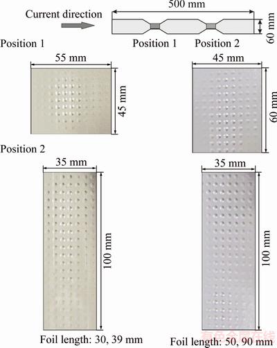
Fig. 15 Perforating formed sheets with respect to different lengths at two tailored positions
6.3 Different polyurethane thicknesses
The polyurethane plate is an important part for this process on mainly two aspects. On one side it is indispensable to induce the shock wave because the vaporized gas moves very quickly and impacts on it firstly. On the other side the polyurethane plate insulates the metal foil from other metal plate over it. As shown in Fig. 16, the pressure distribution induced by thinner polyurethane plate shows larger area than that generated by thicker polyurethane plate. For example, the width of the pressure area in the case of polyurethane plate 7 mm is about 13 mm larger than that in the case of polyurethane plate 10 mm.
As the thickness of the polyurethane plate gets larger, the dissipation of the shock amplitude is increased because the shock wave must travel a longer distance until it reaches the interface of the polyurethane plate and the sheet metal. The increased number of internal interfaces enhances the scattering effect on the shock wave, which results in an attenuation of pressure amplitude.
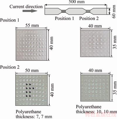
Fig. 16 Tailored pressure distribution with respect to different polyurethane thicknesses at two tailoring positions
7 Double-direction pressure distribution
The double-direction pressure distribution could increase the productivity and provide new forming method for metal profiles [17]. The aluminum foil with thickness of 0.06 mm is chosen as the electrical actuator. Two polyurethane plates in hardness 90 A are positioned next to the aluminum foil on its both sides (see Fig. 17). Around the polyurethane plates are the containers made of polyethylene in high density (PE-HD) which has enough strength to be a structure part and excellent insulation property. Two pressure films and metal sheets Al 1050 with thickness of 1 mm are placed on the top of the upper container and at the bottom of the lower container. Thus, the whole setup is completely symmetric to the metal foil in the middle. After the discharge of the capacitor bank, the high current will pass through the aluminum foil and heat it. Due to the Joule heating effect, the aluminum foil is firstly melted and finally vaporized into gas or plasma which travels thereafter further in the two directions. In this work, the aluminum foils are vaporized at various input energy levels which are 3, 4 and 5 kJ, respectively. The pressure distributions in the double-direction pressure mode are measured by means of the pressure film.
The pressure distributions revealed in Fig. 18 indicate that the shock pressure is mainly concentrated in the middle of the part. The pressure area corresponds to the vaporized region of the metal foil. Besides, there is also shock pressure separately located on both sides of the pressure in the middle. With increasing the charging energy of the capacitor bank, the pressure area in the middle together with the other two on its both sides are enlarged until they connect with each other to cover the whole part vertically. According to the depth of color of the red stain which reflects the loading amplitude exerted on it, the shock pressure is also enhanced under a higher electrical energy. In addition, the pressure distributions on both sides of the metal foil in the double pressure mode do not show much difference but seem to be similar with each other with respect to the pressure area.
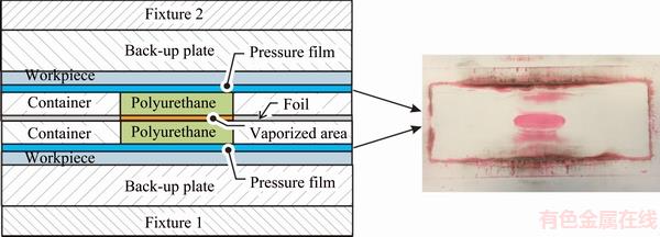
Fig. 17 Principle of measurement for double-direction pressure distribution
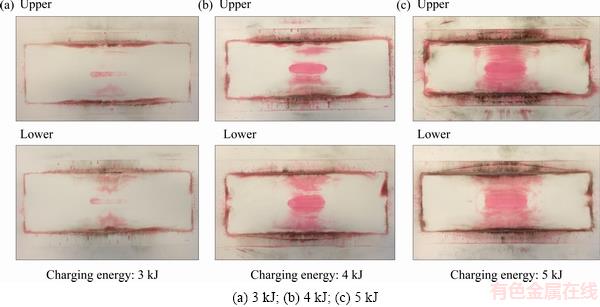
Fig. 18 Pressure distributions under different charging energies
After the discharge of the capacitor bank, the total amount of the vaporized gas or plasma expands upward and downward at the same time. The amount of the metal gas or plasma in the two directions can be treated as the same with each other. Therefore, the shock pressures in the two directions are close to each other and can be approximately seen as the same. Hence, the double pressure mode can realize a loading approach in the two directions simultaneously and at least two parts can be achieved within one forming operation.
8 Conclusions
1) In single pressure distribution, the length of the generated pressure area is mainly determined by the vaporized foil length. As decreasing the foil geometry, the induced pressure area could be extended in the transverse direction.
2) The pressure in tailored pressure distribution is located at two separate positions. Changing the geometry of the foil at two tailoring positions resulted in various pressure distributions. The same tailored foil geometries result in the same shock pressure areas at two separate positions. Increasing the vaporized length of the foil at two positions enlarges the pressure area. When the foil at two tailoring positions had the same width but different length, the pressure area on the long vaporized side is larger than that on the shorter side. The deposited electric energy is absorbed more by the longer vaporized foil. Using different polyurethane plates at two positions is another effective method to vary the pressure distributions.
3) The double-direction pressure distribution is achieved by vaporizing metal foil using two polyurethane plates symmetrically on its both sides. The pressure distributions on the both sides of the foil have the same area with each other. Within a certain range of application the two shock pressures on both sides of the metal foil can be treated as the same.
Acknowledgements
The German Academic Exchange Service (DAAD) provides financial support for this paper, which is gratefully acknowledged here. The experiments in this work are conducted at the Institute of Forming Technology and Lightweight Construction, TU Dortmund.
References
[1] PSYK V, RISCH D, KINSEY B L, TEKKAYA A E, KLEINER M. Electromagnetic forming��A review [J]. Journal of Materials Processing Technology, 2011, 211(5): 787-829.
[2] WANG Du-zhen, LI Ning, HAN Xiao-tao, LI Liang, LIU Lin. Effect of electromagnetic bulging on fatigue behavior of 5052 aluminum alloy [J]. Transactions of Nonferrous Metals Society of China, 2017, 27(6): 1224-1232.
[3] LUCA D. Finite element modeling and experiment for behavior estimation of AlMn0.5Mg0.5 sheet during electromagnetic forming [J]. Transactions of Nonferrous Metals Society of China, 2015, 25(7): 2331-2341.
[4] KELLER D V, PENNING J R. Exploding foils��The production of plane shock waves and the acceleration of thin plates [C]// CHACE W G, MOORE H K. Exploding Wires. Boston, USA: Springer, 2012: 263-277.
[5] GUENTHER A H, WUNSCH D C, SOAPES T D. Acceleration of thin plates by exploding foil techniques [C]// CHACE W G, MOORE H K. Exploding Wires 2. Boston, USA: Springer, 2012: 279-298.
[6] VIVEK A, TABER G A, JOHNSON J R, WOODWARD S T, DAEHN G S. Electrically driven plasma via vaporization of metallic conductors: A tool for impulse metal working [J]. Journal of Materials Processing Technology, 2013, 213: 1311-1326.
[7] VIVEK A, BRUNE R C, HANSEN S R, DAEHN G S. Vaporizing foil actuator used for impulse forming and embossing of titanium and aluminum alloys [J]. Journal of Materials Processing Technology, 2014, 214: 865-875.
[8] VIVEK A, HANSEN S R, LIU B C, DAEHN G S. Vaporizing foil actuator: A tool for collision welding [J]. Journal of Materials Processing Technology, 2013, 213: 2304-2311.
[9] VIVEK A. Rapid vaporization of thin conductors used for impulse metalworking [D]. Ohio: Ohio State University, 2012.
[10] GRUNER M, MERKLEIN M. Numerical simulation of hydro forming at elevated temperatures with granular material used as medium compared to the real part geometry [J]. International Journal of Material Forming, 2010, 3: 279-282.
[11] YOUNGDAHL C K. Correlation parameters for eliminating the effect of pulse shape on dynamic plastic deformation [J]. Journal of Applied Mechanics, 1970, 39: 744-752.
[12] HODGE P G Jr. Impact pressure loading of rigid-plastic cylindrical shells [J]. Journal of the Mechanics and Physics of Solids, 1955, 3: 176-188.
[13] JONES N. Structural impact [M]. Cambridge: Cambridge University Press, 1989.
[14] COX A D, MORLAND L W. Dynamic plastic deformations of simply supported square plates [J]. Journal of the Mechanics and Physics of Solids, 1959, 7: 229-241.
[15] MARTIN J B. Impulsive loading theorems for rigid-plastic continua [J]. Journal of the Engineering Mechanics Division, 1964, 90: 27-42.
[16] CAI Sheng. Tailored pressure distributions generated by vaporizing tailored metal foils [J]. International Journal of Advanced Manufacturing Technology, doi: 10.1007/s00170-017-1068-5
[17] CAI Sheng. Double-direction pressure distributions generated by vaporizing metal foils [J]. Journal of Manufacturing Science and Engineering, doi: 10.1115/1.4034494.
�����������IJ�����ѹ���ֲ�
�� ʤ
�й�ũҵ��ѧ ��ѧԺ ��������ϵ������ 100083
ժ Ҫ���о������������IJ�����ѹ���ֲ�������һ������ģ�ͣ������������ΰ���ڶ�̬�����µ���ѧ��Ϊ�����ù�ѧ����ϵͳ��������������ij��μ����з������������ֲ���ѹ���ֲ��ķ����������ǽ��бȽϡ���Ĵ���ʵ���ѹ����Ĥ���Dz���ѹ���ֲ�����Ч��������Ĵ���ʵ��ijɱ����ͣ���ѹ����Ĥ�IJ��������㡣�Ե���ѹ���ֲ����ü�ʽ��ѹ���ֲ���˫��ѹ���ֲ����в��������ۣ���3��ѹ���ֲ�����Ӧ�õ���ͬ�Ľ������ι����С�
�ؼ��ʣ�ѹ���ֲ����������ģ�������ģ��������
(Edited by Xiang-qun LI)
Corresponding author: Sheng CAI; Tel: +86-18311107105; E-mail: sheng.cai@gmx.de
DOI: 10.1016/S1003-6326(18)64850-2
Abstract: The pressure distributions generated by vaporizing metal foils were studied. An analytical model which described the dynamic mechanical behavior of a rectangular plate under an impulsive loading was introduced. The formed parts of free bulging tests were analyzed using the optical measurement system. Two measurement methods for pressure distributions were introduced and compared. Both the perforated sheet forming test and the pressure film were found to be effective method to measure pressure distributions. The cost of perforated sheet forming test was cheap and the pressure film was easy to operate. Three different pressure distributions were measured and discussed, namely single pressure distribution, tailored pressure distribution and double-direction pressure distribution. These three pressure distributions could be applied in different metal forming processes.
