
Trans. Nonferrous Met. Soc. China 24(2014) 969-974
Effect of laser shock processing on fatigue life of fastener hole
Xing-quan ZHANG, Liu-san CHEN, Xiao-liu YU, Li-sheng ZUO, Yu ZHOU
School of Mechanical Engineering, Anhui University of Technology, Ma��anshan 243002, China
Received 11 March 2013; accepted 4 September 2013
Abstract:
The fatigue properties of laser shock processing (LSP) on both side surfaces of fastener hole with diameter of 3 mm in the LY12CZ aluminum alloy specimens were investigated. The superficial residual stress was measured by X-ray diffraction method. Fatigue experiments of specimens with and without LSP were performed, and the microstructural features of fracture of specimens were characterized by scanning electron microscopy (SEM). The results indicate that the compressive residual stress can be induced into the surface of specimen, and the fatigue life of the specimen with LSP is 3.5 times as long as that of specimen without LSP. The location of fatigue crack initiation is transferred from the top surface to the sub-surface after LSP, and the fatigue striation spacing of the treated specimen during the expanding fatigue crack is narrower than that of the untreated specimen. Furthermore, the diameters of the dimples on the fatigue crack rupture zone of the specimen with LSP are relatively bigger, which is related to the serious plastic deformation in the material with LSP.
Key words:
laser shock processing; fastener hole; fatigue life; LY12CZ;
1 Introduction
Laser shock processing (LSP) is a promising surface treatment technique to improve the fatigue properties of some metals and alloys [1-3]. LSP can also improve mechanical properties of material, such as hardness and yield stress. Compared with the traditional methods [4-7], LSP effectively generates higher magnitude and deeper compressive residual stresses in material surface layer, so the resistance to stress corrosion of the treated material immensely enhances and its fatigue life is dramatically extended. Now, LSP is recognized as an efficient tool to improve the resistance of metal surfaces against fatigue, wear or corrosion aggressions.
It is well known that the fastener holes in airplane skin are used to joint skin parts into the whole body with rivets or bolts. The fastener hole with small size easily leads to stress concentration in machining and assembly processing, and the fatigue crack likely originates in the corner of the fastener hole and propagates inward the base body, so the security and the service life of airplane correspondingly reduce [8-10]. Therefore, it is significant for improving fatigue resistance property of the fastener hole to guarantee the security of the airplane and extend its service life. In engineering practice, some traditional strengthening technologies are brought into operation to the fastener hole, such as rod extruding [11] and shot peening [12], but the depth and the amplitude of the compressive residue stress induced by them are extremely limited. Moreover, they are difficult to strengthen the smaller holes with diameter smaller than 2.5 mm, which are widely used in plane for joining skins and airframes. So the alternative technologies are acquired to meet the needs of higher quality requirements. Laser shock peening is an effectively strengthening technology for part with fastener hole. IVETIC et al [13] examined the influence of the sequence of operations on the effectiveness of LSP on the fatigue performances of open-hole in 6082-T6 aluminum. The results indicated that fatigue performances in thin aluminium specimens were improved by the inducement of compressive residual stress. However, few attentions have been paid to the microstructural features of fracture of aluminum specimens with and without LSP.
The objective of the present work was to identify the effect of LSP on the fatigue behavior of the fastener hole. The residual stress was measured by the X-ray diffraction method. The fatigue crack initiation and the microstructural features of fracture of aluminum specimens with and without LSP were characterized by scanning electron microscopy (SEM). The change of the fatigue crack initiation location and the fatigue striation spacing on fatigue fracture surface were investigated.
2 Experimental
2.1 Material and sample preparation
LY12CZ aeronautical aluminum alloy is a kind of light alloy, which possesses excellent performance, such as low density, high strength, good plasticity, so it has been used widely in airplane as skin and airframe [14]. Its chemical composition and mechanical properties are shown in Tables 1 and 2, respectively. It was dealt with solid solution and natural aging. The specimens were cut from the same plate with 3 mm thickness, and the dimension is shown in Fig. 1. After a single pulse laser shocking on both side central zones in specimen, the central hole with diameter of 3 mm was drilled. The sharp corner of central hole was polished by SiC paper with grade of abrasive grains 600, and the specimen was finally cleaned by the distilled water and dried in the air.
Table 1 Chemical compositions of LY12CZ Al alloy (mass fraction, %)
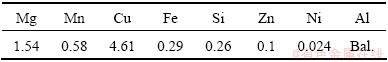
Table 2 Mechanical properties of LY12CZ Al alloy
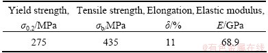
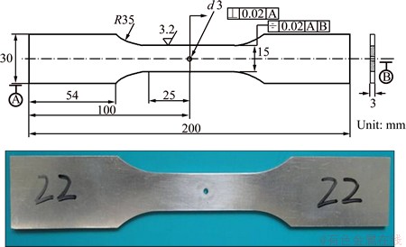
Fig. 1 Dimension and shape of specimen
2.2 Principle and experimental procedure of LSP
Prior to the laser shock, the surface zone prepared to be treated was covered by two layers. One was an ablative layer, which directly covered the specimen and was served as a protective layer to substitute for metal sheet and produce high pressure plasma. The other was a flowing water confining layer with thickness more than 2 mm, which was served to retard the plasma expansion to get higher pressure and longer duration. After two layers were in place, the LSP experiment can be carried out. A single high energy laser pulse traveled through the water confining layer and irradiated the surface of an ablative layer. The ablative layer absorbed the laser energy to produce high pressure plasma. The high pressure plasma exerted the high pressure on the surface of metal sheet and induced the stress wave propagating into the metal target. When the magnitude of stress went beyond the dynamic yield strength of material, the plastic deformation occurred and the compressive residual stress generated in the irradiated area [15-17]. After one side surface was shocked, the other side was next to be irradiated at once. During the present LSP, the specimen was treated by a Q-switched repetition-rate laser with a laser beam wavelength of 1.064 ��m, pulse duration of 23 ns, the output energy of 25 J per pulse and its local spot of 8 mm in diameter.
2.3 Residual stress measurement
The residual stress was measured with the X-ray diffraction with sin2�� method. In the present work, the stress instrument X-350A was used, whose collimator diameter was 1 mm, and the high pressure and current of X-ray pipe were 20 kV and 5.0 mA, respectively. The X-ray source was Cr K��. In order to test the effect of drilling hole on the residual stress distribution, the surface stresses at each selected point in central zone were measured before and after drilling hole, respectively.
2.4 Fatigue test equipment
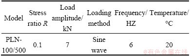
Fatigue tests were performed for different specimens, the shocked and the un-shocked, on an electro-hydraulic servo control test machine in the same condition. The selected parameters in the fatigue experiments are shown in Table 3.
Table 3 Condition of fatigue experiments
2.5 Fracture morphologies observation
The fractured end of the broken specimen after the fatigue test was taken down to study its fracture morphologies. The fracture surface was observed by scanning electron microscopy (SEM, JSM-6490LV).
3 Results and discussion
3.1 Measurement result of residual stress
After the LSP treatment, a distinct permanent indentation was left in irradiated surface, which was easily found in Fig. 1. The surface residual stresses measured along the width direction of specimen are shown in Fig. 2.
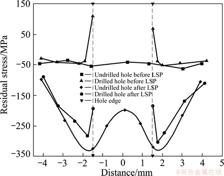
Fig. 2 Residual stress along spot diameter
It can be seen from Fig. 2 that the LSP can effectively induce the compressive residual stresses in the laser affected zone. The profile of the residual stresses presents approximately the W shape. With the increase of distance away from the spot centre, the compressive residual stress first gradually increases and then decreases to original value. At the spot centre, the compressive residual stress is about 200 MPa. At the location of 1.6 mm radius, the residual stress reaches the maximum, 320 MPa. The smaller magnitude of compressive stress at the spot center can be attributed to surface wave action. Because the laser circle spot is employed in laser shock processing, and the surface waves, such as Rayleigh wave and shearing strain wave, generate near the spot edge [18,19]. These waves sequentially propagate to the spot centre and interact with each other there. Therefore, the reverse plastic waves come into the spot centre, and reduce greatly the preliminary residual stress induced by laser shocking. This phenomenon is called ��Residual stress hole�� in Ref. [20].
It is easily found in Fig. 2 that the residual stresses are partly redistributed after drilling hole. The compressive residual stress near the hole edge drops from 280 to 190 MPa in the shocked specimen, because the material near the hole edge is removed and the compressive residual stress releases greatly. Moreover, the detrimental tensile stresses are also found at the edge of hole in the untreated case, which is bad for the fatigue life.
3.2 Analysis of fatigue experiment
The specimens with and without laser irradiating were tested under the cyclic loading as the above mentioned, and finally broke into two pieces, as shown in Fig. 3. It can be seen that the specimen has no phenomenon of drawing and necking down, which is different from tensile failure. During the fatigue loading action, the data of the axial displacements versus the fatigue cycles were recorded, and the curves based on the recorded data are shown in Fig. 4. It can be found that the initial axial displacement of the un-shocked specimen is approximately 0.27 mm. With the increasing of cycle, the axial displacement finally increases to 0.298 mm before fracture, and its ultimate fatigue life is 77720 cycles. The responding initial axial displacement in the case of the treated specimen is 0.122 mm. When its following value rises to 0.152 mm, the shocked specimen is pulled off, and its final fatigue life adds up to 275420 cycles, about 350% longer than that of untreated case, which reveals that the LSP treatment appears to be an effective approach to increase the fatigue life of fastener hole.
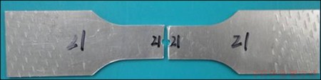
Fig. 3 Image of material object after fracture
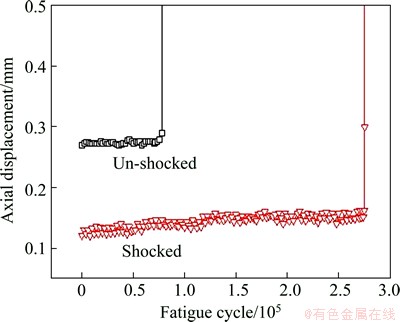
Fig. 4 Axial displacement versus fatigue cycle index in fatigue experiment
3.3 Fatigue fracture morphologies
The fatigue life of component relies closely on the surface manufacturing quality. Under the cyclic loading, the fatigue crack initiation always originates from the weak point, where the stress or strain concentrates. The micro-crack forms, progressively expands, and finally abruptly fractures. The above tested experiments, from the macro perspective, verify that the LSP treatment is helpful for improving the fatigue life. In terms of microcosmic view, it is necessary to identify the effect of the LSP treatment on the mechanical and fatigue properties including the crack initiation location, crack growth rate and the final fracture zone.
Figure 5 shows typical fracture morphologies of fatigue crack initiation region of hole with and without LSP treatment. Figure 5(a) shows the SEM morphology of the specimen without LSP, and Figure 5(b) shows the morphology of the specimen subjected to LSP. It can be seen from Fig. 5(a) that the fatigue crack initiation of the un-shocked occurs in the corner of hole, and gradually expands into the body of the specimen. The corner is the sharp-angled place where the inner surface of hole and surface plane intersect, and the stress concentration easily grows. From Fig. 5(b), the LSP affected layer in depth is obviously seen, and the fatigue crack initiation point has been transported to the sub-surface from the superficial layer and emerges at inner wall of hole. As a result of the LSP treatment, the material grains are refined [16,21], and the high density dislocations are induced into the treated surface layer, which contribute to the improvement of surface hardness and surface residual stress. Hence, the fatigue crack initiation location is compelled to migrate from the top treated layer to the untreated sub-surface where surface quality is relatively low.
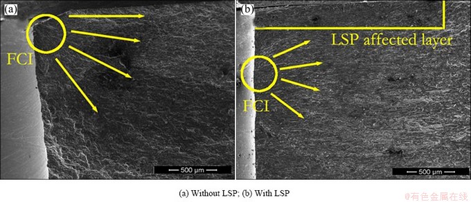
Fig. 5 Morphologies of fatigue crack initiation region on LY12CZ specimens
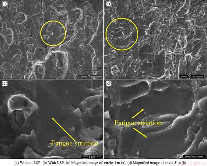
Fig. 6 Morphologies of fatigue crack grouth region on LY12CZ specimens
After crack nucleation has formed under the cyclic loading, the crack experiences the stable growth for a while, and specimen factures little by little during the period. Figures 6(a) and (b) show the fracture morphologies of fatigue crack growth at this stage of fastening hole without and with LSP treatment, respectively. Figures 6(c) and (d) show the magnified graphs of the marked zones in Figs. 6(a) and (b), respectively. It can be observed clearly that the fairly typical fatigue striations exist and occupy a large portion of the fatigue plateaus. These fatigue striations are parallel to each other and perpendicular to crack expanding direction. Every striation is corresponding to a loading cycle. But the average fatigue striation spacing of the un-shocked is larger than that of the shocked, and the density of the fracture striations in the LSP treatment is higher than that of non-LSP case. In addition, more micro-cliffs can be found along the fatigue crack path of specimen subjected to the LSP treatment.
The variation of the fatigue striation spacing is closely concerned with the stress intensity factor range (��K) at the local area of crack tip, and the fatigue crack growth rate da/dN is proportional to (��K)4 [22], so the relationship between the fatigue crack growth rate da/dN and the fatigue striations spacing can be established through ��K. Consequently, the narrower fatigue striation spacing represents the slower fatigue crack growth rate da/dN of specimen with the LSP treatment, which shows the LSP treatment can prevent crack growth and contribute to extending fatigue life.
Figure 7 displays many dimples on the fatigue crack rapidly expanding region where the distance from the
spot center equals 3.5 mm. Some inclusions are also clearly seen. The fracture shows the similar characteristic with a ductile material [23]. When the stress imposed by the external loading exceeds yield strength of material, plastic deformation occurs. At the same time, inclusions, precipitated phase, grain boundaries, sub-boundaries and other plastic flowing places in material generate dislocation pile-up, where stress concentration produces and some micro cavities may form. With the increase of the strain, micro cavities further grow up, so there are many isometric dimples on the fracture surface, and the inclusion lies at the bottom of dimples. Nonetheless, it can be seen from the Figs. 7(a) and (b) that the dimples on the fatigue fracture of specimen treated by laser are bigger than those of the untreated specimen, and some tear ridges are also found on the outside of dimples of the treated specimen fracture, which demonstrate that serious plastic deformation occurs before the fracture of the specimen with the LSP treatment.
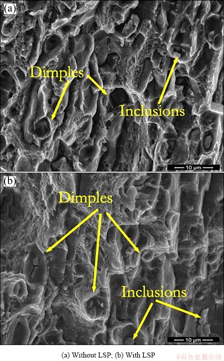
Fig. 7 Final fracture morphologies of LY12CZ specimens
4 Conclusions
1) The compressive residual stress can be squeezed into the material surface subjected to LSP, and its value in the spot central zone is smaller, which is attributed to surface wave action. After drilling hole in LSP treated zone, the compressive residual stress amplitude near the edge of hole has a sharp decline.
2) The quality of surface treated by LSP was improved. The location of fatigue crack initiation transferred from the top surface to the sub-surface after laser shock, and the fatigue striation spacing with shocked was smaller than the average fatigue striation spacing of the un-shocked.
3) Under the sine wave cyclic loading condition, fatigue crack growth was effectively affected by LSP, and its expanding rate became slower. The fatigue life of fastener hole treated by LSP was 3.5 times as long as that of the un-treated.
References
[1] FORGET P, STRUDEL J L, JEANDIN M, LU J, CASTEX L. Laser shock surface treatment of Ni-based super alloys [J]. Materials and Manufacturing Processes, 1990, 5(4): 501-528.
[2] ZHANG X C, ZHANG Y K, LU J Z, XUAN F Z, WANG Z D, TU S T. Improvement of fatigue life of Ti-6Al-4V alloy by laser shock peening [J]. Materials Science and Engineering A, 2010, 527: 3411-3415.
[3] MONTROSS C S, TAO W, LIN Y, GRAHAM C, MAI Y W. Laser shock processing and its effects on microstructure and properties of metal alloys: A review [J]. International Journal of Fatigue, 2002, 24: 1021-1036.
[4] GAO Y K, Wu X R. Experimental investigation and fatigue life prediction for7475-T7351 aluminum alloy with and without shot peening-induced residual stresses [J]. Acta Materialia, 2011, 59: 3737-3747.
[5] REAL E,  C, BELZUNCE F J, SANJURJO P, CANTELI A F, PARIENTE I F. Fatigue behaviour of duplex stainless steel reinforcing bars subjected to shot peening [J]. Fatigue and Fracture of Engineering Materials and Structures, 2009, 32(7): 567-572.
[6] LING Chao, ZHENG Xiu-li. The effect of cold expansion on FCIL of LY12CZ alloy [J]. Acta Aeronautica Et Astronautica Sinica, 1991, 12(1): 83-86. (in Chinese)
[7] CHAKHERLOU T N , VOGWELL J. The effect of cold expansion on improving the fatigue life of fastener holes [J]. Engineering Failure Analysis, 2003, 10(1): 13-24.
[8] XIE Wei-dong, WU Fu-min, XIAO Shou-ting. Stress-strain analysis and fatigue life prediction of interference joints [J]. Acta Aeronautica Et Astronautica Sinica, 1988, 9: 58-64. (in Chinese)
[9] ZOU Shi-kun, GAO Zi-wen, ZHAO Yong, QIAN Ming. Laser peening of aluminum alloy 7050 with fastener holes [J]. Chinese Optics Letters, 2008, 6(2): 116-119.
[10] ZHANG Hong, TANG Ya-xin, YU Cheng-ye, ZHANG Yong-kang, GUO Da-hao, WU Hong-xing. Effects of laser shock processing on the fatigue life of fastener holes [J]. Chinese Journal of Lasers, 1996, 23(12): 1112-1116. (in Chinese)
[11] DING Chuan-fu, ZHAO Zhen-ye, SONG De-yu. Effect of cold worked holes on the iniation life and propagation life of fatigue cracks in two ultra-high strength steels [J]. Acta Aeronautica Et Astronautica Sinica, 1994, 15(8): 960-967.
[12] LI Yuan, LEI Li-ping, ZENG Pan. Shot stream finite element model for shot peening numerical simulation and its experiment study [J]. Journal of Mechanical Engineering, 2011, 47(22): 43-48. (in Chinese)
[13] IVETIC G, MENEGHIN I, TROIANI E, MOLINARI G. Fatigue in laser shock peened open-hole thin aluminium specimens [J]. Materials Science and Engineering A, 2012, 534: 573-579.
[14] QIAN Xiao-ming, JIANG Yin-fang, GUAN Hai-bing, LI Zhi-fei. Research and application of strengthening technology for fastening holes of aircraft structures [J]. Journal of Mechanical Strength, 2011, 33(5): 749-753. (in Chinese)
[15] TAN Y, WU G, YANG J M, PAN T. Laser shock peening on fatigue crack growth behaviour of aluminium alloy [J]. Fatigue & Fracture of Engineering Materials & Structures, 2004, 27 (8): 649-656.
[16] LU J Z, LUO K Y, ZHANG Y K. Grain refinement mechanism of multiple laser shock processing impacts on ANSI 304 stainless steel [J]. Acta Materialia, 2010, 58: 5354-5362.
[17] PEYRE P, SOLLIER A, CHAIEB I, BERTHE L, BARTNICKI E, BRAHAM C, FABBRO R. FEM simulation of residual stresses induced by laser peening [J]. The European Physical Journal Applied Physics, 2003, 23: 83-88.
[18] ZHANG Xing-quan, ZHANG Yong-kang, ZHOU Jian-zhong, GU Yong-yu, YANG Chao-jun. Experimental research on narrow strip laser peening forming [J]. Chinese Journal of Lasers, 2007, 34(10): 1446-1450. (in Chinese)
[19] ZHANG Xing-quan, ZHANG Yong-kang, ZHOU Jian-zhong, GU Yong-yu. Finite element analysis of narrow strip laser peening forming [J]. Acta Aeronautica et Astronautica Sinica, 2009, 30(4): 744-750. (in Chinese)
[20] PEYRE P, FABBRO R, MERRIEN P, LIEURADE H P. Laser shock processing of aluminium alloys. Application to high cycle fatigue behaviour [J]. Materials Science and Engineering A, 1996, 210(1-2): 102-113.
[21] LU J Z, LUO K Y, ZHANG Y K, CUI C Y, SUN G F, ZHOU J Z, ZHANG L, YOU J, CHEN K M, ZHONG J W. Grain refinement of LY2 aluminum alloy induced by ultra-high plastic strain during multiple laser shock processing impacts [J]. Acta Materialia, 2010, 58: 3984-3994.
[22] FROST N E. Fatigue invalidation analysis [M]. WANG Ren-zhi, WU Pei-yuan. Beijing: China Machine Press, 1987: 125-136. (in Chinese)
[23] YUAN S P, WANG R H, LIU G, LI R, PARK J M, SUN J, CHEN K H. Effects of precipitate morphology on the notch sensitivity of ductile fracture in heat-treatable aluminum alloys [J]. Materials Science and Engineering A, 2010, 527: 7369-7381.
������ǿ���Խ��̿�ƣ��������Ӱ��
����Ȩ���������������������������� ��
���չ�ҵ��ѧ ��е����ѧԺ������ɽ 243002
ժ Ҫ���о��������Ժ������Ͻ�LY12CZ���̿�ƣ�����Ե�Ӱ�죬��ֱ��Ϊd3 mm������X�������䷨��������Ӧ�������Լ�����ƣ�Ͷ���ʵ�飬����ɨ���������(SEM)�۲��Լ�ƣ�ͶϿڵ���������������������������ڽ��̿����γɲ���ѹӦ��������Լ���ƣ��������δ�����3.5����ͨ���ϿڵĹ۲�ͱȽϷ��֣�������Լ���ƣ������Դ�ڴα��㣬������Դ���Լ����㣬�����ƣ�ͶϿڿ�����չ����ƣ�����Ƽ���δ����Լ�ƣ�ͶϿڿ�����չ����ƣ�����Ƽ��ҪС�����⣬�ڳ���Լ����������������Ա�δ�����Ҫ��������ʱ�����ڷ������Ա����йء�
�ؼ��ʣ�������ǿ�������̿ף�ƣ��������LY12CZ
(Edited by Chao WANG)
Foundation item: Project (51175002) supported by the National Natural Science Foundation of China; Project (090414156) supported by the Natural Science Foundation of Anhui Province, China
Corresponding author: Xing-quan ZHANG; Tel: +86-15552316517; E-mail: zhxq@ahut.edu.cn
DOI: 10.1016/S1003-6326(14)63150-2
Abstract: The fatigue properties of laser shock processing (LSP) on both side surfaces of fastener hole with diameter of 3 mm in the LY12CZ aluminum alloy specimens were investigated. The superficial residual stress was measured by X-ray diffraction method. Fatigue experiments of specimens with and without LSP were performed, and the microstructural features of fracture of specimens were characterized by scanning electron microscopy (SEM). The results indicate that the compressive residual stress can be induced into the surface of specimen, and the fatigue life of the specimen with LSP is 3.5 times as long as that of specimen without LSP. The location of fatigue crack initiation is transferred from the top surface to the sub-surface after LSP, and the fatigue striation spacing of the treated specimen during the expanding fatigue crack is narrower than that of the untreated specimen. Furthermore, the diameters of the dimples on the fatigue crack rupture zone of the specimen with LSP are relatively bigger, which is related to the serious plastic deformation in the material with LSP.
