

Defect analysis of complex-shape aluminum alloy forging
SHAN De-bin(���±�), ZHANG Yan-qiu(������), WANG Yong(�� ��),
XU Fu-chang(�츣��), XU Wen-chen(���ij�), L? Yan(�� ��)
School of Materials Science and Engineering, Harbin Institute of Technology, Harbin 150001, China
Received 28 July 2006; accepted 15 September 2006
Abstract:
The isothermal precision forging was applied for the purpose of forming aluminum alloy with complex shape. The complexity of forging is easy to lead to the occurrence of the defects, such as underfilling, folding, metal flow lines disturbance and fibre breaking. The reasons for the defects were analyzed on the basis of experiments and finite element method(FEM). The results show that the size of flash gutter bridge, the lubricating condition and the deformation process are the main factors influencing the filling qualities of complex-shape aluminum alloy forging. The folding defect is mainly caused by different velocities of filling cavities, fast flow of much metal in one direction and confluence of two or multi metal strands. Improper metal distribution in different regions can cause the flow lines disturbance and fast metal flow in one direction is also a cause of the flow lines disturbance. According to the reasons, some measures were taken to improve the quality of the forged parts.These studies can contribute to offering some experiences in making process project and optimizing the process parameters for forging complex-shape aviation products.
Key words:
aluminum alloy; defect analysis; isothermal precision forging; FEM; metal forming;
1 Introduction
With the development of aircraft and aerospace structures toward light mass, high precision and low cost, various integral complex-shape aluminum alloy forgings are applied more and more widely. In addition, high dimension accuracy, good mechanical properties and well-distributed internal structure are required[1-3]. The complex-shape forging made by precision forming processes has either no working allowance or only a little working allowance, and the forging has thinner wall thickness, smaller round radius as well as higher precision than usual. Furthermore, it��s much more difficult to precisely form complex-shape forging than to precisely form simple-shape one. The defects such as underfilling, folding, flow lines disturbance and fibre breaking are the primary factors to restrict the practical application of complex-shape forging, which are difficult to overcome because of complex metal flow[4].
In recent years, computer simulation technology in metal forming is most efficient for solving the forging process problems and its applications have increased steadily[5-12], which can be combined with the experiments to explain the reason of forming defects. LI et al[13] analyzed the factors resulting in a folding defect in an aluminum alloy rear lower arm forging using FEM and put forward the means of eliminating the folding defect. JOUN et al[14] gave two application examples to emphasize the significance of metal flow lines for quality control. ZHAO et al [15] investigated the folding defects, the extensive flash and underfill resulting from using an improper initial billet size with FEM. However, few mechanism analyses of complex-shape forging defects using FEM can be found in the related literatures.
In this paper, isothermal precision forging processes were studied and defects of complex-shape forging were especially analyzed by experiments and rigid-plastic FEM. Based on these methods, the mechanism and influencing factors of defects arising in the forming of complex-shape part were studied, and some measures were taken so as to improve the quality of the part.
2 Analysis of underfilling
Because the deformation of complex-shape aluminum alloy forging is a complex process of metal flowing, there are many factors influencing the filling qualities. Some of them are the reasons of shape and size of the part, such as the rib height, the draft angle and the round radius, which needn��t be manufactured after precision forging, so these sizes can��t be modified in the forging design. In this paper, the following factors were discussed.
2.1 Size of flash gutter bridge
The function of flash gutter bridge is to prevent the flow-out of metal toward the flash and force the metal to fill the cavity completely. The flash gutter bridge can increase the resistance force of mould to billet. When the resistance in bridge is less than the resistance in cavity, much metal will flow towards the flash gutter bridge before the cavity is filled and the cavity underfilling ultimately is led to. But the resistance in bridge can��t be too large, too large resistance in bridge will result in the deformation of the overlarge resistance, which makes it hard to close the upper and lower moulds.
2.2 Lubricating condition
Friction resistance plays an important role on the process of filling cavity. The more large friction coefficient between mould and workpiece, the more difficultly the cavity is filled. Fig. 1 shows the influence of friction coefficient on pressure in a simple forging simulation. It can be seen that the pressure increases with increasing friction coefficient ��, especially in the final stage forging. Therefore, in order to create a favorable condition of filling cavity, smoothness of cavity should be advanced and the lubricant with good lubricating property should be used.
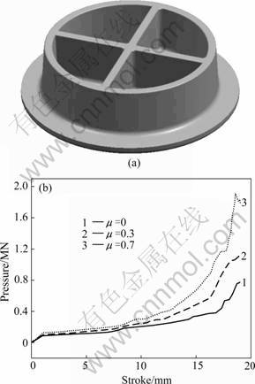
Fig.1 Influence of friction coefficient on pressure: (a) Model of simulated forging; (b) Curves of pressure vs stroke
2.3 Deformation process
In precision bulk forming, the thin rib and end corner of complex-shape aluminum alloy forging often can��t be filled. Increasing resistance in bridge usually causes pressure increase greatly, which may make the mould damaged. Sometimes it can��t satisfy the quality requirement even though the measures above are taken. The reason is that the pathways of metal flowing are all blocked and the plastic deformation happens difficultly, or there are obstacles in the direction of metal flowing. In these conditions, the following measures can be taken.
1) Adding the preforging procedure. In order to decrease the resistance of cavity, the forging processes of some complex-shaped aluminum alloy forging should be divided into the two procedures, namely preforging and finish-forging. More parameters such as the rib height, the draft angle and the round radius can be changed in the preforging step so that the finishing cavities can be filled easily. This method may decrease the deformation quantum or skip over the obstacles in the finish-forging step. Fig.2 shows the filling quality of an aluminum alloy rotor ring under different processes. It can be seen that the ears are underfilled because of obstacles under non-preforging billet, while under preforging billet, the ears are filled very well.
2) Adopting local loading method. Because the underfilling happens only in the exceptional regions in precision forging, the local loading method can be applied for the forging with large plane size. Fig.3 shows an aluminum alloy hatch forged by whole loading and local loading methods. It can be seen that a majority of the ellipse rib is not filled under whole loading method, while under local loading method, it is filled very well.
3 Analysis of folding
Folding is a common phenomenon that happens in the plastic bulk forging, it is one of the most important factor influencing the service performance of forging. Folding is caused by confluence of the oxidized surface metal in the process of metal flowing. In part of the structures, folding is a hidden trouble, which reduces the load-supporting area of part, and often becomes the fatigue source because of stress concentration, especially when the fold stripe is vertical to the stress direction. In the complex-shape aluminum alloy die forging, the type and position of folding generally follow some laws. In terms of plastic deformation, the types and causing reasons of folding are as follows.
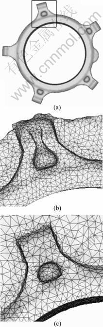
Fig.2 Filling quality under different processes: (a) Forging of rotor ring; (b) Simulation of forging with non-preforging billet; (c) Simulation of forging with preforging billet
1) Different velocity of filling cavities. In the process of isothermal precision forging, when the metal in some regions flows slower than others, the metal of early filled cavities will flow to here to form folding. Fig.4 shows the folding occurring in a fixed rotor ring. In the forging process, metal in the ears flows faster than that of ribs, so the cavities of the former are filled earlier than the latter, and the redundant metal is forced to flow to the rib cavities and lead to folding. The effective measure of preventing this kind of folding is to adopt preforging to form the billet into a suitable shape, which can make the metal fill the cavities almost at the same time.
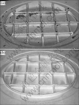
Fig.3 Aluminum alloy hatch forged by whole loading and local loading methods: (a) Whole loading; (b) Local loading
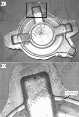
Fig.4 Folding caused by different velocities of filling cavities: (a) Rotor ring seat; (b) Partial enlarged detail
2) Fast flow of much metal in one direction. This kind of folding mainly happens in the forging whose shape of cross-section looks like ��H�� or ������. A simple model is established here in order to analyze the reasons leading to folding, as is shown in Fig.5.
In the stage when the cavities are almost filled, because the resistance in cavities is larger than that in
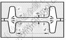
Fig.5 Process of folding formationin H-shape forging
bridge. The metal near the contact surface ��ab�� (especially in the thin web part) will flow greatly outwards in the horizontal direction, and the metal near ��ac�� and ��bd�� will be brought to flow outwards to flash, which may make the oxidized surface metal merge to form folding. In order to illuminate it, the metal deformation of this area is supposed to be a plane strain state, as shown in Fig.5. Suppose the velocity of upper die is vy, the moving distance of it in time ��t is ��h. Let��s support that the moving distance of metal near ��ac�� and ��bd�� is ��l, the velocity of metal flowing outwards in horizontal direction is v, then Eqns.(1) and (2) can be obtained.
vy=��h/��t (1)
v=��l/��t (2)
According to the volume constancy principle, as is shown in Fig.6, Eqns.(3) and (4) can be drawn:
��l=l��h/h (3)
v=lvy/h (4)
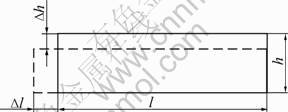
Fig.6 Sketch maps of metal deformation in center area
So it can be seen that the larger the l/h is, the more easily the folding is caused. Fig.7 shows the folding phenomenon in the fixed rotor ring caused by the reason above. If the rib is very thin and the metal flows too fast, the rib breaking will be caused. Fig.8 shows the sketch map of rib breaking.
In order to prevent the folding above, the following measures can be taken.
1) Try to reduce the deformation of finish forging, which can decrease the metal overflow from center area.
2) Enhance the resistance in flash gutter bridge to force the metal flow into cavity rather than outwards.
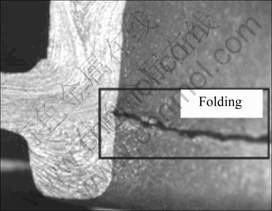
Fig.7 Folding phenomenon caused by fast flow of much metal in one direction
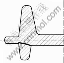
Fig. 8 Sketch map of rib breaking
3) For the forging with hole in center, excavate the center of billet after preforging and making wad in finish-forging are recommended, which can make the metal near ��ac�� and ��bd�� flow inwards to wad, and the folding will be prevented.
4) Confluence of two or multi metal strands. This kind of folding usually happens in the forging with intercrossing ribs. In the forging process of multi-ribs part, metal flows along the lateral wall to fill the rib cavities, which causes the outer corners to be filled prior to the inner corners, as shown in Fig.9. So in the area of two ribs intercrossing, a concave zone is formed in the inside corner because of lacking in metal. If the die pressing continues, the oxidized surface metal of concave zone will meet together and folding is posed. Fig.10 shows the simulation process of folding formed in a rib-web part with intercrossing ribs. Adopting local loading method can effectively prevent this kind of folding, because these areas can be filled in time.
4 Analysis of flow lines disturbance and fibre breaking
The flow lines disturbance is the phenomenon that metal lines don��t distribute along the geometric shape of forging. There are two main reasons causing the defect.
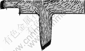
Fig.9 Velocity distribution of multi-ribs part
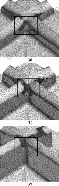
Fig.10 Process of folding forming: (a) 11 mm; (b) 13 mm; (c) 15 mm
1) Improper metal distribution in different regions.
In the process of forging complex-shape part, metal distribution in different regions plays an important role. If the cavities in some places are lack of metal, the redundant metal of surrounding regions will turn back to fill them to cause the flow lines disturbance. Fig.11 shows this kind of flow lines disturbance happening in the fixed rotor ring forging. So accurate calculation is required in designing the billet and preforging process should be used in forging the complex part.
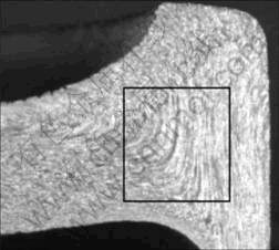
Fig.11 Flow lines disturbance caused by improper metal distribution in different directions
2) Fast metal flow in one direction.
This kind of the flow lines disturbance and the fibre breaking are both caused by this reason, which usually happen in the complex structures with thin and high ribs. The fibre breaking is an exceptional case of this kind of the flow lines disturbance. Its characteristic is that flow lines are cut off in the root of ribs. When the structure is forged in mould, the metal flows towards the two directions: Some flows towards the cavities to form the ribs, some flows in the horizontal direction to form the flash. The direction of metal flow mainly depends on the resistance of the two directions. When the resistance of cavities is larger (such as in the high and thin ribs), a large quantity of metal will be forced to flow outwards to form the flash or inwards to form the wad, and leads to the problems such as the flow lines disturbance and the fibre breaking. These problems often happen in the late stage of mould forging when the cavities are almost filled. If die pressing continues, large quantity of metal will flow along the web, and the flow lines disturbance or the fibre breaking is posed. Fig.12 shows the flow lines disturbance and the fibre breaking caused by this reason. Therefore, enhancing resistance of flash gutter bridge or of wad (such as enlarging the width of flash gutter bridge or reducing the thickness of wad) should be taken in order to solve these defects.
5 Conclusions
1) The size of flash gutter bridge, the lubricat- ing condition and the deformation process are the main factors influencing the filling qualities of complex-shape aluminum alloy forging. Enhancing resistance of flash gutter bridge, reducing friction resistance of mould cavities and adopting suitable forging process are capable of solving the problems effectively.
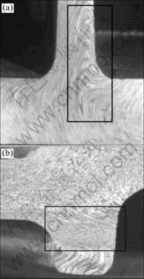
Fig.12 Flow lines disturbance and fibre breaking caused by fast metal flow in one direction: (a) Flow lines disturbance; (b) Fibre breaking
2) Folding defect is mainly caused by different velocity of filling cavities, fast flow of much metal in one direction and confluence of two or multi metal strands. Therefore, the appropriate billet shape, the high resistance of flash gutter bridge and reasonable forging process make a contribution to avoiding this kind of defect.
3) Improper metal distribution in different regions can cause the flow lines disturbance, which should be solved by designing precision billet and using preforging process. Fast metal flow in one direction can also cause the flow lines disturbance, which can even cause the fibre breaking when the metal flows too fast. Enhancing resistance of flash gutter bridge or of wad contributes to solving these problems.
References
[1] SIEGERT K, KAMMERER M, KEPPLER-OTT T H, RINGHAND D. Recent developments on high precision forging of aluminum and steel [J]. J Mater Process Technol, 1997, 71: 91-99.
[2] SHAN D B, XU W C, LU Y. Study on precision forging technology for a complex-shaped light alloy forging [J]. J Mater Process Technol, 2004, 151: 289-293.
[3] YOSHIMURA H, TANAKA K. Precision forging of aluminum and steel [J]. J Mater Process Technol, 2000, 98: 196-204.
[4] YANG He, ZHAN Mei, LIU Yu-li. A 3D rigid-viscoplastic FEM simulation of the isothermal precision forging of a blade with a damper latform [J]. J Mater Process Technol, 2002, 122: 45-50.
[5] ZIENKIEWICZ P N, Godbole. Flow of plastic and visco-plastic solids with special reference to extrusion and forming processes [J]. Int J Num Methods Eng, 1974, 8: 3-16.
[6] HARTLEY P P, STURGESS C E N, ROWE R W. Finite-element modelling of metal flow in three-dimensional forming [J]. Int J Mach Tool Des Res, 1985, 25: 229-243.
[7] SURDON S, CHENOT J L. Finite element calculation of three-dimensional hot forging [J]. Int J Num Methods Eng, 1987, 24: 2107-2117.
[8] OH S I, WU W T, TANG J P, VEDHANAYAGAM A. Capabilities and application of FEM code DEFORM: the perspective of the developer [J]. J Mater Process Technol, 1991, 27: 25-42.
[9] JOUN M S, HWANG S M. Optimal process design in steady-state metal forming by finite element method(I): Theoretical consideration [J]. Int J Mach Tools Manufact, 1993, 33: 51-61.
[10] SHAN De-bin, YI Xu, YAN Lu. Three-dimensional rigid-plastic finite-element analysis of the isothermal precision forging of a cylindrical housing [J]. J Mater Process Technol, 2000,102: 188-192.
[11] MIN D K, KIM M E. A study on precision cold forging process improvements for the steering yoke of automobiles by the rigid-plastic finite-element method [J]. J Mater Process Technol, 2003, 138: 339-342.
[12] ZHAN Mei, YANG He, LIU Yu-li. Deformation characteristic of the precision forging of a blade with a damper platform using 3D FEM analysis [J]. J Mater Process Technol, 2004, 150: 290-299.
[13] LI Pei-wu, ZHAO Guo-qun, OSAWA Y. Application of the finite-element method in the reform of light-weight vehicle construction [J]. J Mater Process Technol, 1996, 62: 211-215.
[14] JOUN M S, LEEA S W, CHUNG B J H. Finite element analysis of a multi-stage axisymmetric forging process [J]. Int J Mach Tools Manufact, 1998, 38: 843-854.
[15] ZHAO Guo-qun, ZHAO Zhen-duo, WANG Tong-hai, GRANDHI R V. Preform design of a generic turbine disk forging process [J]. J Mater Process Technol, 1998, 84: 193-201.
Corresponding author: SHAN De-bin; Tel: +86-451-86418732; E-mail: shandb@hit.edu.cn
