
Trans. Nonferrous Met. Soc. China 28(2018) 193-219
Review on underwater friction stir welding: A variant of friction stir welding with great potential of improving joint properties
Mohd. Atif WAHID, Zahid A. KHAN, Arshad Noor SIDDIQUEE
Department of Mechanical Engineering, Jamia Millia Islamia, New Delhi, India
Received 5 December 2016; accepted 18 April 2017
Abstract:
Friction stir welding (FSW) is a solid-state welding process which is capable of joining materials which are relatively difficult to be welded by fusion welding process. Further, this process is highly energy-efficient and environmental-friendly as compared to the fusion welding. Despite several advantages of FSW over fusion welding, the thermal cycles involved in FSW cause softening in joints generally in heat-treatable aluminum alloys (AAs) due to the dissolution or coarsening of the strengthening precipitates leading to decrease in mechanical properties. Underwater friction stir welding (UFSW) can be a process of choice to overcome these limitations. This process is suitable for alloys that are sensitive to heating during the welding and is widely used for heat-treatable AAs. The purpose of this article is to provide comprehensive literature review on current status and development of UFSW and its importance in comparison to FSW with an aim to discuss and summarize different aspects of UFSW. Specific attention is given to basic principle including material flow, temperature generation, process parameters, microstructure and mechanical properties. From the review, it is concluded that UFSW is an improved method compared with FSW for improving joint strength. Academicians, researchers and practitioners would be benefitted from this article as it compiles significantly important knowledge pertaining to UFSW.
Key words:
aluminum; friction stir welding; fusion welding; mechanical properties; microstructure; underwater friction stir welding;
1 Introduction
The joining of materials has been an essential issue for several ages. In general, various problems have been found in traditional fusion welding (FW) with regard to welding of different alloys, i.e., aluminum [1] and magnesium [2]. Welding discontinuities such as cracks, voids, porosity and inclusions during FW significantly affect the quality and mechanical properties of the welds. In 1990��s, a solid state welding process, friction stir welding (FSW) was developed by The Welding Institute (UK) [3]. This process is competent enough to weld materials which are relatively difficult to be welded or almost unweldable by FW process. The major aspect of this process is that the temperature remains below the solidus temperature, i.e., melting of the material does not take place. As the welding takes place below the solidus temperature, various defects associated with the FW process are not present in FSW, leading to outstanding weld strength and ductility. Further, this process is highly energy-efficient and less prone to environment than existing FW processes. Additionally, distortion in the final products is also reduced due to the decrease in the residual stresses owing to reduced thermal flux [4,5]. FSW was initially developed for aluminum alloys (AA), but subsequently, it was employed to many different materials and alloys. FSW is found extensive application in aerospace, automobile, railway, shipbuilding and offshore construction [6-8].
In FSW, a non-consumable rotating tool with a profiled probe and shoulder is plunged into the substrate as the force is applied vertically downward. The friction between the tool and workpiece increases the temperature in the weld region which softens the materials being welded and the workpiece gets plastically deformed easily. As such, a softening region is created around the pin, leading to the reduction in the resistance to deformation of the base material. The tool is also traversed along the joint line which causes the material movement from advancing side (AS) to retreating side (RS) and the tool shoulder consolidates the material at the back side of the pin leading to a solid joint. As a result of this, a joint is produced in ��solid state�� [9-13]. The working principle of FSW is schematically shown in Fig. 1 [9].
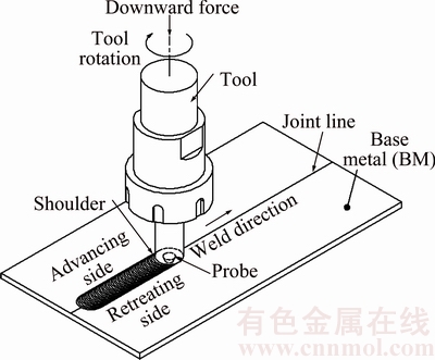
Fig. 1 Schematic diagram of FSW process [9]
FSW leads to fine grain structure in the stir region due to dynamic recrystallization owing to severe plastic deformation, resulting in substantial microstructural evolution [14-17]. Due to this fine microstructure, good mechanical properties are observed in FSW. Even though the heat input in FSW is low as compared to FW, it is high enough to cause softening generally in heat treatable AAs. The softening is due to the dissolution or coarsening of the strengthening precipitates, leading to decreased mechanical performance of the joints [18-20]. In order to resolve these issues, a method that enhances the cooling rate and lowers the peak temperature can be used to improve properties of the joint in FSW. In this regard, external cooling has been employed in several solid state joining processes to improve the joint performances [21-23]. Water cooling method has also been investigated to provide cooling effect on the samples during FSW because of its extensive circulation and exceptional heat absorption capability.
UFSW is a modification of the FSW in which the water as the coolant is employed to normalize the temperature profiles existing in the weld joint [24-26]. Fundamentally, the welding is performed under water, either in a water container or in a state where water continually flows across the surface of the sample, as shown in Fig 2.
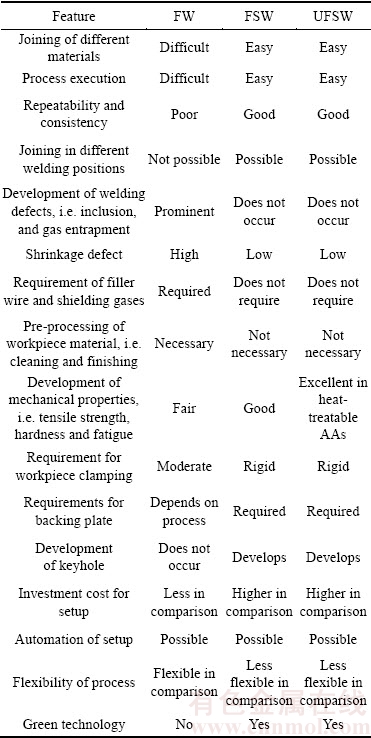
During UFSW, the high heat absorption capacity of water manages the transmission of heat to thermo- mechanically affected zone (TMAZ) and heat affected zone (HAZ). Thus, the low heat existing in the TMAZ and HAZ due to cooling is not adequate for coarsening of the precipitates [27]. Also, the TMAZ and HAZ width is narrowed by restricting the heat input and plastic deformation by UFSW [27,28]. UFSW gives improved mechanical properties by minimizing various welding defects like porosity, shrinkage, and solidification cracking. It also provides well-defined variation in grain size in different zones along the joint and therefore, a high quality weld joint is produced. This process is suitable for alloys that are sensitive to overheating during the welding process and it is widely used for AAs [29]. UFSW has diverse marine and offshore applications. It is widely used in shipbuilding, submarines, oil and fuel tanks and various offshore structures involving fabrication and repair. UFSW is gaining importance as a very valuable welding process due to its ability to provide superior mechanical properties over FSW and FW [25-27,30]. Table 1 presents a comparison of UFSW with FSW and FW with respect to various features to demonstrate the advantages and benefits of UFSW.
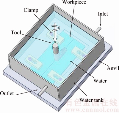
Fig. 2 Schematic diagram of UFSW
The benefits of UFSW over FSW are as follows.
1) USFW is suitable for materials and alloys that are sensitive to overheating.
2) Development of peak temperature is lower in UFSW than in FSW, limiting the coarsening and precipitate dissolution.
3) UFSW provides the better mechanical properties of the workpiece materials than FSW.
4) UFSW prevents the oxidation and provides better surface texture than FSW.
5) UFSW offers refined grain structure as compared to FSW.
6) UFSW is more suitable to heat-treatable aluminum alloys as it reduces the softening effect.
7) Less welding defects are observed in UFSW than in FSW.
8) Development of intermetallic compounds is less in UFSW than in FSW.
9) UFSW reduces the residual stresses and creates less distortion than FSW.
UFSW is relatively a new variant of FSW due to which very few investigations pertaining to the UFSW has been reported so far. In this work, comprehensive literature review on the current status and development of UFSW employed mostly for AAs and some dissimilar materials and its importance in comparison to FSW is presented.
Table 1 Comparison of fusion and solid state welding process
2 Process parameters
Different welding variables, joint configuration and tool geometry offer considerable effect on the material movement and temperature distributed across the weld in UFSW, thus affecting the microstructure of the material.
2.1 Tool design and material
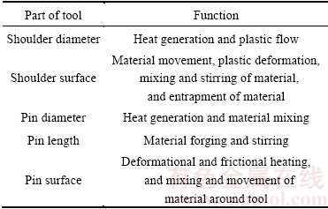
For the success of the FSW/UFSW process, FSW tool plays a significant role. Heat evolved, material flow, power requirement and consistency of the joints produced are influenced by the tool design. The tool design contains a shoulder and a probe that heats up the material. Most of the heat is generated by the shoulder which helps in compacting the plasticized material, thus preventing escaping of the material from the workpiece. The flow of material is affected both by tool shoulder and pin. The functions performed by different features of the tool are listed in Table 2.
Table 2 Functions of different features of tool
Important factors in tool design are diameter of shoulder and its surface, and geometry of the probe including its size and shape [31-34].
Previous researches have revealed the importance of shoulder size and surface on resulting properties of the FSW weld [35-38]. Increase in diameter of shoulder leads to increase in temperature due to high frictional work. In a study [35], tools with three different diameters were used for FSW of AA 6061 and it was found that only one diameter resulted in improved tensile properties of the joint. Thus, it is considered that a tool with a particular optimum diameter results in improved properties of the joint in FSW [35,36]. In order to obtain best results in FSW, for given material and welding parameter, the shoulder diameter should correspond to the maximum sticking torque [36]. The nature of the tool shoulder surface is also an important aspect of tool design. The shoulder having various profiles such as flat surface [26,27,34], concave [33,38] or convex surface has been widely used in UFSW. Different shoulder surface feature is shown in Fig. 3(a). The flat shoulder is simple in design but it cannot trap the flowing material efficiently under the bottom surface leading to flash. To avoid this, a concave shoulder is used which helps in directing the material flow to the centre near the probe providing an advantage on its use over flat shoulder. A convex surface suffers from weld integrity issue as it displaces the material further away from the probe. Shoulder bottom surface also has additional features to increase friction and material deformation to enhance the material mixing [39]. Some of the bottom surface features are smooth, grooved, scroll and concentric circles, are shown in Fig. 3(b). A grooved bottom moves the material towards the centre of the probe, thus offering an advantage over smooth bottom. Spiral channels in scrolled surface also offer the same phenomenon helping in flow of material from the shoulder periphery to the probe [40]. Moreover, improved process stability is observed in convex shoulder with scrolls in FSW [41]. Additionally, scrolled concave shoulder reduces lifting of the tool at high welding speed [42].
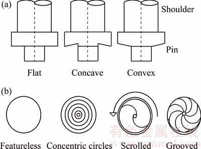
Fig. 3 Tool with different shoulder profiles (a) and shoulder bottom surface features (b)
Rotating probe in FSW/UFSW produces both frictional and deformational heating. Probe causes shearing of the material at the face of the tool and moves it behind the tool. Plunge depth and welding speed are generally managed by the probe. The important elements of probe are length, diameter and surface feature of the probe. Probe elements have their effects on the size of the stir zone, and microstructure and pattern of material flow. Probe is either flat or domed in shape but in general flat shape is used due to simplicity in design [25,34,43]. Dome shape is also used due to its advantage over flat shape in reducing the forging force during plunging. The outer surface of the probe can be cylindrical [34,43] or taper [34]. Moreover, additional features (threads, flutes, etc) are also integrated on the outer surface [34], as can be seen in Figs. 4(c) and 4(d).
SABARI et al [34] performed UFSW to weld AA2059-T87 using different probe profiles, i.e. straight cylindrical, cylindrical threaded, cylindrical tapered, and tapered threaded. It was observed that non-threaded probe resulted in defects while threaded profile yielded defect-free joints. In FSW/UFSW, the generation of heat and material movement is categorized into insufficient state, balance state and excess state. The tool probe profile plays a significant role in managing these states. If correct probe profile is employed, good quality joints without defects can be obtained [44]. Straight and tapered cylindrical probe due to its plain and featureless surface causes less friction over the softened material and does not allow intensive deformation, and thus, the optimum combination of heat generation and flow of material (insufficient state) is not met in the welded region. This leads to defects in the joint produced. The threaded profile offers more friction over the softened material and causes intensive deformation of material. Thus, the degree of heat input and plastic deformation is optimum for attaining the sufficient state of heat and material movement in threaded probe profile, leading to defect-free joint. In general, the defects formation takes place in the periphery of welded joints, i.e. the transformed layers around the probe region, hence the probe profile should be optimum such that it should be able to form sufficient transforming layers. Due to high plastic deformation and shearing of material, threaded probe profile yields sound joint by generating sufficient transforming layers. Probe geometry also affects the forces applied on the tool during welding. Both axial and translational forces increase significantly as probe geometry changes from threaded to triangular in AA 7075-T6 alloy [45]. Triangular probe profile causes pulsating action that affects the material movement, causing increased forces on tool.
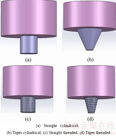
Fig. 4 Different probe profiles
Some intricate features have been included in tool geometry to modify flow of material and mixing. For instance, Whorl and MX Triflute tools have been developed by TWI [46]. The pins of these tools are shaped as frustum of cone, leading to less displacement of material as compared to cylindrical tool. These tools enable high heat generation and easy flow of material. Some new pin geometries, i.e. Flared-Triflute (flutes flared out) and A-skew (axis of pin minorly inclined to spindle axis), have also been developed. These probe profiles enhance the flow of material around the probe and also lead to the improvement in mixing of material [47].
Shoulder to probe ratio also affects the quality of the weld. It depends upon the workpiece material and its thickness. Higher shoulder to probe ratio is required for higher thickness of workpiece [37].
Tool material also plays a vital role in producing defect-free weld. The choice of tool material depends on the workpiece material and the tool life. The selected tool material must be strong, hard and tough at elevated temperature. Furthermore, it should be highly oxidation and wear resistant. Soft materials (aluminum, magnesium, etc) are easily weldable by tool steels while carbide and polycrystalline cubic boron nitride (PCBN) tools are required for the welding of harder materials. AISI H13 tool steel [25,33,38] is generally used for welding AAs in UFSW due to its high toughness and machinability.
Thus, it is observed that proper tool and probe geometry leads to defect-free joint in FSW/UFSW. Tool design and material is selected based on the workpiece material, its properties and thickness and once chosen is not varied during the welding process. Others parameters (rotational speed, welding speed, etc) can be varied for the same tool design and geometry. These variable parameters are discussed in the following section below.
2.2 Welding parameters
The important welding parameters affecting the quality of welded joint are rotational speed of the tool, welding speed of the tool, tool tilt angle, force exerted by the tool (axial force) and plunge depth. These parameters and properties of the material are accountable for the distribution of temperature, rate of cooling and torque applied by the tool. The important functions and effect of these parameters are given in Table 3.
Table 3 Principal welding parameters in FSW/UFSW
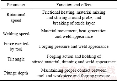
Tool rotational speed governs the material mixing and stirring around the probe and the mixed material is moved from the face to the backside of the probe due to translation of the tool, thus resulting in quality joint. The increased rotational speed of the tool results in high temperature and frictional heat leading to more stirred and mixed material [27,48,49]. With increased rotational speed, torque also increases, if tool tilt angle, coefficient of friction and welding speed are kept constant [50]. As the heating is governed by frictional pairing of the tool/workpiece, monotonic increase in heating is not possible at increased tool rotation speed due to change in the frictional coefficient at interface owing to change in rotational speed. Too high rotational speed causes excessive heat input and too low rotational speed causes inadequate stirring of the material by the tool, and both these situations lead to deterioration in mechanical properties and defects, as observed in AA 2219 [27] and AA 2519 T-87 [49]. Moreover, the axial and translational forces on tool decrease with increase in rotational speed, as observed in AA 7075-T6 in UFSW [45]. Thus, it can be observed that for obtaining good mechanical properties and defect-free UFSW joint, rotational speed must be chosen properly. The rotational speed should be selected such that the stirring of the tool can significantly enhance the microstructure and properties of the SZ and the heat generated neither worsens the mechanical properties of HAZ and TMAZ nor causes defects in SZ.
Welding speed should also be selected carefully for obtaining defect-free weld. Too low welding speed raises the heat input into the welded samples, leading to excessive softening of the material generally in heat-treatable AAs [45,51]. The excessive material softening encourages slipping condition due to decrease in friction between the tool and the workpiece material, resulting in the formation of defects in the SZ and leading to poor joint quality. When the welding speed is increased, both the plastic deformation of the material and the heat generation decrease. As such, inadequate heat generation and insufficient material flow take place, again leading to defective joint in AA 2519-T87 [52]. Also, the axial and translational forces on the tool increase with increasing welding speed in UFSW of 7075-T6 AA [45].
Another important welding parameter is tilting of the tool from the axis normal to the workpiece. An appropriate tilting of the tool helps in making sure that the stirred material is properly held by the tool shoulder and moves efficiently around the probe. For thickness up to 4 mm and the tool tilt of 1��, the strength of the weld is found good. Tool tilt angle should be increased with increase in plate thickness [53].
When the axial force is large, tool wear and tool fracture can take place, and thus the force applied by the tool at the interface of the welded material must be taken into consideration. Force on tool can be measured by dynamometer which may assist in predicting the defect formation [54]. In UFSW, forces developed on the tool and their effect on the heat input and thermal cycles are analyzed by PAPHN et al [45]. Vertical axial and translational forces are developed on the tool and these forces are improved significantly under water due to reduction in peak temperature.
Moreover, for producing sound quality welds, the portion of probe height into the plate (plunge depth) is significant. Plunge depth causes increase in the pressure below the shoulder surface and leads to sufficient forging action at the front of the tool. If the plunge depth is low, tool shoulder does not contact the work surface properly, leading to inefficient movement of the stirred material around the pin and thus resulting in surface groove. Too large plunge depth leads to excessive flash due to excessive forging. Increased plunge depth up to certain level improves the consolidation of the deformed material and enhances the stirring and inter-mingling of the material, leading to improvement in strength [55,56]. Thus, plunge depth should be set correctly ensuring full penetration of the tool and maintaining necessary forging pressure.
Furthermore, in a study by KISHTA and DARRAS [57] during FSW and UFSW of AA 5083, it was obtained that due to high thermal capacity and cooling rate of water, high rotational rate and welding speed in comparison to FSW are required in UFSW for producing high quality welds. High rotation speed increases the frictional heat of material and increases the speed of circulating water which accelerates heat dissipation and cooling rate. The increase in welding speed allows shorter duration time at a particular temperature, leading to low heat input and accelerating the cooling process.
Thus, it can be concluded that rotation and welding speed should be specified properly for obtaining qualified joints. Sufficient tool tilt and plunge depth are also required for sound quality of the joints produced by UFSW.
2.3 Joint design
The commonly used joint designs for UFSW are lap [58] and butt joint (as shown in Fig. 1) [29,30,59]. In butt joint, sheets of similar thickness are put on the back plate and are rigidly clamped with the help of fixture to prevent welded faces from moving apart under the forces developed during welding. The back plate helps in resisting the normal forces related to UFSW and the workpiece. In lap joint (see Fig. 5(a)), two plates are held together with the help of fixture and depending upon less sheet thickness back plate may be used or not. FSW tool is moved downward inside the two plates and moved towards the welding direction, thus producing weld.

Fig. 5 Different joint designs
Several additional designs can also be fabricated by combining lap and butt joints. UFSW can also be used for welding of various types of joints, such as scarf, T (see Figs. 5(b, c)), and fillet joints.
It can be concluded that tool geometry and welding parameters greatly affect the material deformation and material flow in FSW/UFSW. The material flow is highly governed by the tool geometry and welding parameter. Therefore, in order to obtain optimum tool geometry and defect-free welds, the material flow should be analyzed and studied efficiently.
3 Mechanical and thermal process
Due to large material deformation and temperature increase in FSW/UFSW, various changes occur in the microstructure and properties of the welded joints. In this regard, a thoughtful study on the mechanical and thermal aspects during FSW/UFSW is required for controlling the weld microstructure and properties.
3.1 Material flow and modeling
The flow of material during UFSW is extremely intricate and it generally depends upon the geometry of the tool, various welding parameters and welded workpiece material. Improper selection of the tool design and parameters generally lead to defects. Hence, understanding the material flow characteristics in UFSW is of prime importance in obtaining high efficiency welds. Numerous methods, such as marker tracing technique [60], analyzing material flow through dissimilar welding of alloys/metals [61], and analyzing the characteristics of welding defects [62,63] can be used to investigate pattern of material flow in FSW/UFSW. Due to complexity in predicting material flow experimentally, additionally, few modeling methods involving few computational codes [64], mathematical modeling [65], geometric model [66] and metal working model [67] can also be used for predicting the material flow.
Material flow in FSW was modeled by COLEGROVE and SHERCLIFF [64] using slip model developed through computational fluid codes. The model revealed different material flow for different types of tool design and the material in path of the probe was displaced around the RS of the tool. Moreover, on the AS, the deformed region for the slip model was smaller than that on RS. The results of the model were well in support with the experiment-based tracer technique of material flow [60]. Five FSW working zones were proposed by ARBEGAST and JIN [67] in a metal working model for material flow. These are preheat zone, extrusion zone, initial deformation zone, forged zone and post heat/cool down zone. The preheat zone is the region neighboring the edge of the shoulder circumference. In this zone, temperature rise takes place due to frictional heat generated by the shoulder and adiabatic heating of the deformed material. The heating of this zone is influenced by the tool welding speed and thermal property of the weld metal. The material temperature rises above the critical temperature due to heating in initial deformation zone. In this zone, flow of material is influenced both in the upward (shoulder zone) and downward (extrusion zone) direction at the bottom of the shoulder and probe. Stirring probe action causes extrusion zone and in this zone material flow takes place around the probe from the front (AS) to the rear (RS). The width of this zone varies depending on the magnitude of stress and distribution of temperature. Next is the forging zone where mixing of the material due to plastic deformation takes place. Depending on the welding speed and rotating speed of the tool, extrusion effect prevails. Cooling and settling of mixed material takes place in the cooling zone. The cooling rate directly influences the tensile property of the weld.
In UFSW, the material flow pattern has been studied by ZHANG and LIU [68]. They suggested three different zones in deformed underwater friction stir welded (UFSWed) joint, i.e., shoulder stirred zone (SSZ), pin stirred zone (PSZ) and TMAZ. SSZ experiences the stirring action of the tool shoulder on the upper part of SZ while the bottom surface of SZ experiences the stirring action of the probe. In SSZ, material is transported from the RS to AS in UFSW. A part of the SSZ transferred material also flows into the PSZ along TMAZ axis grain direction. This pattern of material flow pattern is referred as ����extruding reflux of SSZ material����. Owing to dissimilar microstructure and different flow directions, extruding reflux material showed distinct boundaries near TMAZ material and the leftover SSZ material. The PSZ showed a turbulent flow pattern and a characteristic structure of ����onion ring���� was seen except for the region near to SSZ. Moreover, two flow patterns are observed in PSZ, i.e. circular flow of material around the tool probe and material flow in upward direction owing to shearing action of the probe threads. Material flow pattern in different deformed zones and model for material flow proposed by ZHANG and LIU [68] are shown in Fig. 6.
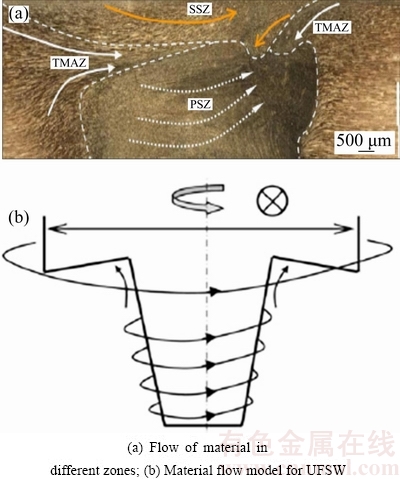
Fig. 6 Material flow in UFSW [68]
Thus, the flow of material in FSW/UFSW is complex and there are many factors (i.e. tool geometry, and welding parameters) influencing the material flow during FSW. It is highly likely that flow of material in the SZ may consist of various deformation processes.
3.2 Temperature measurement and distribution
In deeply understanding the FSW process, complete information of the heat input and temperature associated with different characteristic zones of the FSW is very important. The evolved microstructure (grain size, coarsening of the precipitates) and the mechanical properties of the friction stir (FS) welds are directly related to the temperature in weld zone. Weld temperature measurements are difficult to perform in FSW as large heat is generated in the weld zone due to high plastic deformation at the interface of workpiece and tool, which is considered as the hottest part in the weld. The movement of the rotation of the tool probe also makes it tricky to determine the SZ temperature. The most importantly used temperature measurement techniques during FSW are implanted temperature devices (thermocouple) in the workpiece [56,57,69-71]. Cooling media also exhibit a considerable effect on the temperature profile and the resulting microstructure and strength in FSW. Therefore, accessing the temperature distribution across the cooled joints is very important in explicating the significance of UFSW.
Very low peak temperature is observed in UFSW compared with the FSW sample due to high heat absorbing capacity of water, leading to improvement in properties of UFSWed joint [57-59,69-74]. Greater heating and cooling rates are also obtained during UFSW leading to shorter dwelling time above a given temperature which also leads to low peak temperature in UFSW [69-71]. ZHAO et al [69] carried out UFSW of spray formed Al 7055 alloy in order to improve joint performance by varying the temperature history. Eight thermocouples, i.e. four on the advancing side (A1-A4) and four on the retreating side (R1-R4), were used for measuring temperature. The maximum temperature measured was 68.5 ��C in water which was 118 ��C lower compared with air owing to extra heat taken away by the water. The peak temperature profiles of AA 7055 in FSW and UFSW are shown in Fig. 7.
Further, the range of temperature observed during FSW on AS and RS showed significant drop and large thermal gradient contrary to UFSW where very less drop in temperature was observed. The reduced temperature and less thermal gradient due to water cooling limited the coarsening of strengthening precipitates, leading to improved joint properties. Thermal gradient profile in FSW and UFSW is shown in Fig. 8.
In a study, FU et al [73] employed three different fluids (air, warm, and cold water) for performing UFSW of AA7050 and carried out an investigation on the temperature, strength, and elongation behavior. Eight- channel thermodetector was used for the measurement of the weld temperature. They revealed the following examinations: 1) The peak temperature of the sample welded in air was the highest at 380 ��C. The peak temperatures of the welded samples were about 220 and 300 ��C, respectively, in cold and hot water; 2) The use of warm water resulted in the greatest mechanical strength and elongation due to restriction it imposes on coarsening of second phase strengthening particles in HAZ; 3) Cold water resulted in increased tensile strength and reduced elongation compared with air. Due to the low temperature developed in cold water, the hardening of the weld joint resulted in decreased elongation. Water cooling also enhances the mechanical properties of the HAZ by controlling the temperature level [70]. Due to low peak temperature and reduced dwelling time at a high temperature in UFSW of AA 2219, the coarsening and dissolution of the precipitate is impeded and the width of precipitate free zone (PFZ) is also controlled leading to hardness improvement in the HAZ. Several other examinations have also established the positive effect of liquid cooling on improvement of strength in FSW joints [22,25,29,33,70-72]. This strength improve- ment is due to cooling action (water) resulting from the controlled temperature distribution and thermal profiles. Moreover, the low peak temperature developed during UFSW due to water cooling can also reduce the formation of intermetallic compounds (IMCs) in Al-Mg [59,75,76] and Al-Cu alloy [58].
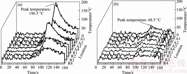
Fig. 7 Peak temperature developed in AA 7055 during FSW (a) and UFSW (b) [69]
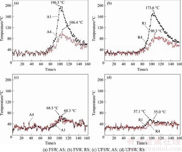
Fig. 8 Temperature cycles showing thermal gradients in AA 7055 at nearest (A1, R1) and farthest (A4, R4) location from weld centre [69]
Maximum temperature developed at different sides also varies in FSW and UFSW. The maximum peak temperature is found in RS in UFSW as compared to FSW in which maximum peak temperature is found in AS, as observed in some 7xxx alloys [71,73]. The AS suffers greater deformation than RS in FSW, leading to higher temperature on AS. In UFSW, on AS, the boiled water near the weld is powered to move frontward confronting the cold water adjacent to the weld and chills down instantaneously and mandatorily while RS receives the heated water coming from AS, and thus UFSWed joint shows high temperature on RS.
The temperature profiles are also affected by the welding parameters. In water surroundings, thermal cycles of the joints are more greatly influenced by changes in welding speed as compared to rotation speed but rotation speed can provide wider adjustment range than welding speed for UFSW process [33]. Fast cooling and high peak temperature are achieved with increasing rotational speed. High welding speed and rotational speed are required for UFSW in comparison to FSW. Forces occurring on the tool are also affected by the heat generation and accordingly the temperature distribution in UFSW/FSW [45]. Axial and translational forces are improved significantly in UFSW of AA 7075-T6 due to reduction in peak temperature.
Due to difficulty in measuring temperature at highly deformed zones experimentally, limited number of temperature modeling studies has been reported in UFSW. Temperature profiles developed during FSW in cooling environment were simulated by FRATINI et al [77] by modeling the coolant as water flux at the back of the tool and reduced thermal flow was observed adjoining the tool due to external cooling. Heat transfer model was developed by ZHANG et al [78] for modeling temperature in UFSW in which modeling was done considering the temperature reliant properties of material. The results indicated low peak temperature and high heat flux of shoulder during UFSW in comparison to FSW. Moreover, peak temperature distributed area is narrowed and temperature profiles in different zones are also low in UFSW as compared to FSW. The model was validated experimentally and showed agreement with experimental values. For obtaining most favorable welding condition for UFSW, AA 2219-T6 was UFSWed by ZHANG and LIU [56] and mathematical modeling was done for optimization of the process parameters for obtaining the highest tensile strength. K-type thermocouples were employed for temperature measurement. They found that tensile strength of 360 MPa was obtained through UFSW which is 6% higher than the tensile strength obtained in FSW. Low peak temperature and correspondingly changed microstructure due to water cooling resulted in strength improvement by UFSW.
From several researches in UFSW, it is observed that UFSW is the suitable method for improving the mechanical properties of the joint due to controlled temperature distribution. Low peak temperature and reduced thermal gradient in UFSW lead to improvement in joint properties as compared to FSW. The thermal cycles, material flow and various process parameters discussed in the above sections lead to changes in microstructure and properties of the welds.
4 Macro/micro structural evolution
4.1 Characteristic zones of FSW/UFSW
FSW microstructure was first characterized by THREADGILL [79]. This work was focused on AAs, and as the behavior of AAs is not the same as other materials and alloys, this characterization was considered inadequate. Accordingly, changed terms were proposed [80] and subsequently modified [81] and implemented in American Welding Society Standard D17.3M [82]. The proposed terms are shown in Fig. 9, and are described as follows.
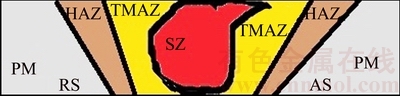
Fig. 9 Different characteristic zones of FSW/UFSW
1) Unaffected material or parent metal: No plastic deformation takes place in this zone but the material may have or have not been affected by the heat of the welding. No noticeable variation in properties and microstructure takes place.
2) Heat affected zone (HAZ): This region is affected by the heat of the welding but no apparent plastic deformation takes places in this zone.
3) Thermomechanically affected zone (TMAZ): In this region, the material is affected both by the plastic deformation and thermal cycles. In AAs, deformed and recrystallized region of TMAZ is separated by a distinctive and clear boundary (this region is frequently termed as ��nugget��. Other names such as SZ and ��dynamically recrystallized region�� are also been used [82]).
The changes in microstructure of different zones directly affect the mechanical properties of the welds produced. Due to large heat and intense deformation experienced during FSW/UFSW, development of different textures [29,30,83,84] and precipitate dissolution and coarsening in different zones take place [34,51,52,70,85]. Different microstructural changes in FSW/UFSW have been analyzed by many researchers. Effect of coolant (water and air) on the grain boundary phases, grains size, defects and growth of intermetallic compounds (IMCs) has also been discussed by various researchers [29,43,58,86].
4.1.1 Stirred zone or nugget zone
Elevated temperature and severe plastic deformation associated with FSW/UFSW lead to typical dynamically recrystallized structure composed of significantly fine and equiaxed grains in SZ [29,43,72,87]. Onion ring patterns are also observed in the SZ directly reflecting the material flowing during FSW [43,73]. It is found that water cooling can result in change of shape of the stirred region. Onion ring structure was observed in the SZ of FSW which was changed to V-shape in the case of UFSW in AA 7050, as shown in Fig. 10 [73]. Also, different strengthening phases also exist in SZ depending upon the temperature and material composition [29,43]. XRD patterns have shown strengthening �� (Al2Cu) phase detected in the SZ of FSW joint in 2xxx AA [29,30]. It is also observed that strengthening phase is sometimes absent in SZ, indicating that precipitates are dissolved in the matrix. Several IMCs also exist in the SZ while joining dissimilar materials such as Al-Cu and Al-Mg [58,59]. In dissimilar welding of Al-Cu by ZHANG et al [58], it was found that SZ consists of the Al-Cu IMCs mainly CuAl2 and Cu9Al4 together with some quantity of Al and Cu. S line feature is also observed in the SZ of AA 7055 during FSW [38,69] and UFSW of AA 7050, as shown in Fig. 10(b) [73]. The ����S line���� is a kind of weak connection defect which determines the characteristics of joints and is generally not present in UFSW. When welding is done in water, the atmospheric oxidation of the plate is prevented, leading to elimination of S line defect. Another reason is that as heat is carried away by water in UFSW, high cooling rate and less thermal gradient are observed in comparison to FSW, leading to elimination of S line defect [38,69,88]. In comparison with FSW, UFSW results in additional refinement of grain size in the SZ (see Fig. 11) due to low peak temperature and low duration at peak temperature [29,43,49,72,89]. This refined structure leads to improvement in mechanical properties of the SZ. UFSW has been successfully used to reduce the amount of brittle IMCs in dissimilar materials such as Al-Cu and Al-Mg due to low peak temperature and short incubation time [58,59,75]. In UFSW, as the residual heat is carried away by the flowing water and the stirred region behind the advancing tool is cooled more rapidly, low peak temperature and little dwell time are observed. As such, fine grains are observed in UFSW and the growth of intermetallic compounds is suppressed.
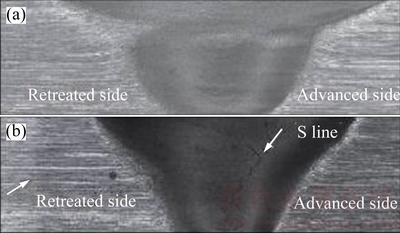
Fig. 10 Macrostructures of SZ of AA 7050 during FSW (a) and UFSW (b )[73]
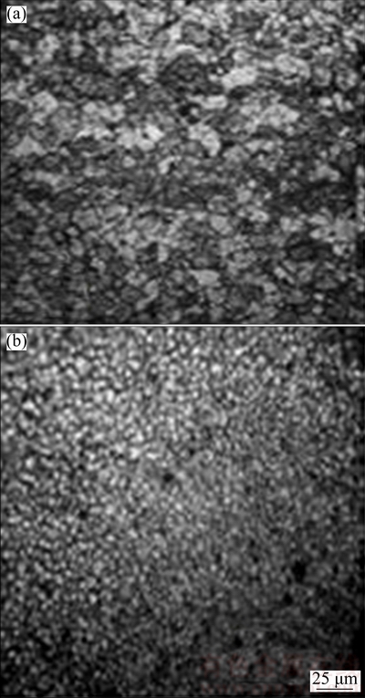
Fig. 11 Microstructures of SZ of AA 2519 during FSW (a) and UFSW (b) [49]
Effect of various process parameters, i.e. welding speed [51], rotational speed [27,33] and probe profile [34], on macro and micro features of SZ produced by FSW/UFSW has also been analysed by various researchers. Size of the grains increases with increase in rotational speed [27,33,49]. At low rotation speed, fine equiaxed grains are observed but their size grows as the rotation speed increases due to increase in heat input in AA 2219 [27] and AA 7075 [33]. Moreover, defects take place in the SZ if welds are not performed at adequate rotational speed [27,33]. At low rotation speed, furrow defects take place due to insufficient material flow [33] and voids are formed in the SZ at too high rotation speed [27]. The voids develop due to turbulence material flow in the SZ owing to high heat input. The size of the grains also varies significantly with alteration in welding speed, as shown in Fig. 12 [51]. In a study, it was observed that grain size first increases with increase in welding speed and then reduces significantly at higher welding speed in AA 2219 [51]. This variation in grain size can be explained as follows: with the increase in welding speed, both heat input and plastic deformation of material are reduced. The reduction in amount of material deformation causes enlargement in size of the grain [84,90], while the reduced heat input results in refinement of the grain [52]. As a result, the difference in sizes of the grain with welding speed depends upon the factor which dominates [51]. With increase in welding speed, the SZ size also gets reduced due to poorer material flow around the probe as observed in AA 2219 [51] and AA 2519 [52]. Studies have also revealed defects at too high welding speed in the SZ [33,51]. Different probe profiles also lead to variation in the grain size of the SZ [34]. The frictional area and heat developed by the probe directly affect the grain size. Less grain size was observed in the joint produced by threaded taper profile tool in comparison to straight threaded tool in both water and air cooling [34]. Further defects are also associated with different probe profiles. In both cooling medium (air and water), the tunnel defects developed in the SZ of the joints were produced using straight and taper cylindrical tools due to insufficient heat in AA 2519 T-87 [34]. Moreover, an interesting result has also been reported in UFSW of accumulative roll bonding (ARB) strain hardenable AA 1050 [72]. The average grain size of 0.8 and 2.1 ��m in UFSW and FSW respectively was found in the SZ. Furthermore, a study on identical alloy shows that by increasing the tool revolutionary pitch (welding speed/rotation speed) up to 2.5 mm/r, the mean grain size in SZ was reduced to about 1.3 ��m in FSW [91]. Therefore, from these results, it is obtained that immersion technique (water) with constant tool rotation and welding speed is more effective method for the refinement of grains in SZ.
4.1.2 TMAZ
This zone is the transition zone between the parent metal zone and the SZ char acterized by a highly deformed structure [10,40]. In the TMAZ, grains do not recrystallize due to low heat input and little deformation. TMAZ region is characterized by highly extruded, elongated and upward oriented grains, as shown in Fig. 13 [34,51,52]. Precipitate evolution and dissolution and coarsening of precipitates are also observed sometimes in the TMAZ of AA 2519 [34,52] and AA 2219 [30,51]. With increase in temperature, the precipitates can get coarse, change to stable state or get dissolved in the matrix during FSW/UFSW. It is found that due to low heat input (increased welding speed) the precipitate deterioration is reduced in TMAZ of AA 2219 [51]. Furthermore, due to low temperature and high cooling rate of water, coarsening of precipitates and grain size in TMAZ (see Fig. 13) is also reduced significantly, leading to improved mechanical properties in AA 2519 [34,52]. Additionally, the width of the TMAZ can also be minimized by restricting the heat and plastic deformation by UFSW [51].
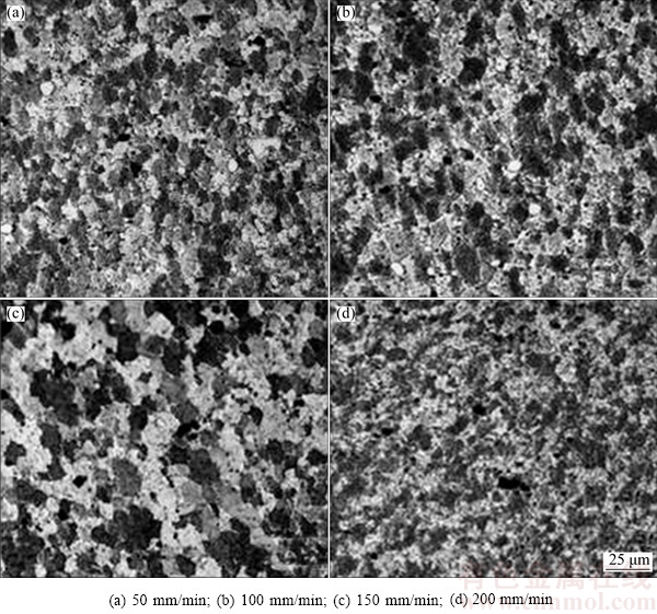
Fig. 12 Grain structures in SZ during UFSW at varying welding speeds [51]
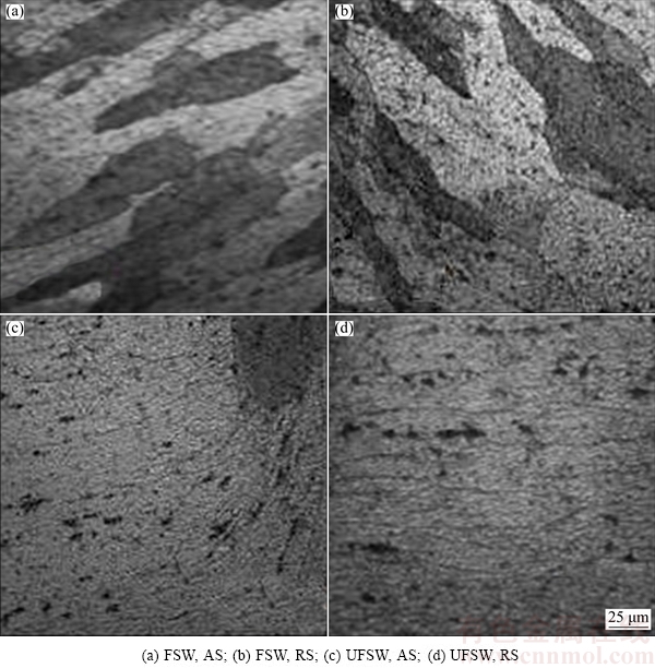
Fig. 13 Micrographs of TMAZ in AA 2519-T 87 at welding speed of 30 mm/min [52]
4.1.3 HAZ
Undeformed coarse grains exist in HAZ (see Fig. 14(a)) as no deformation takes place in this region [27,28,51,52]. Structure of the grain in HAZ remains the same as the structure of grains of the parent material but the temperature over 250 ��C causes notable changes in precipitate structure. Many researchers have shown that FSW/UFSW results in coarsening of the precipitate [34,51,52,70,92] and evolution of precipitate- free zones (PFZ) in the HAZ (see Fig. 14(b)) [34,51,70]. Recently, ZHANG et al [70] have examined the microstructure of AA 2219-T6. It was observed that grain size is not affected by cooling medium but precipitate coarsening and width of the PFZ get reduced in UFSW leading to increased hardness in the HAZ as compared to FSW [70]. Furthermore, larger number of precipitates are observed in UFSW as compared to FSW due to reduced level of dissolution leading to improved mechanical properties in UFSW [34,52].
4.2 Welding defects
Various imperfections (voids, grooves, tunnels, kissing bond, etc) are observed in FSW/UFSW [27,33, 68,93]. Welding parameters along with the cooling medium govern the material flow in FSW/UFSW. Defects are formed in UFSW if the plasticized material is cooled down prior to filling of the joint behind the tool. Defects generally occur due to improper rate of heating if the welding parameters are not chosen properly.
Furrow defects (see Fig. 15(a)) and voids (see Fig. 15(d)) are generally observed at too low and too high rotational speed, respectively, in UFSW. These defects are caused by insufficient material flow and are seen on the surface of the weld or beneath it. At low rotation speed, furrow defect is observed in AA 7055 in SZ [33] and voids are observed in the SZ at too high rotation speed in AA 2219 [27,68] during UFSW. Increasing the rotational speed from lower value to higher value decreases or eliminates these defects, but the size of the voids gets increased if rotational speed is increased from higher value to a further higher level [68].
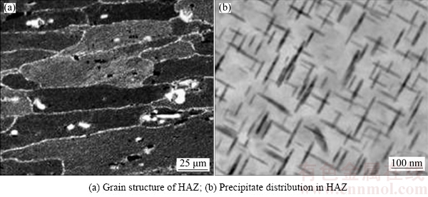
Fig. 14 Microstructures of HAZ of AA 2219 during UFSW [51]
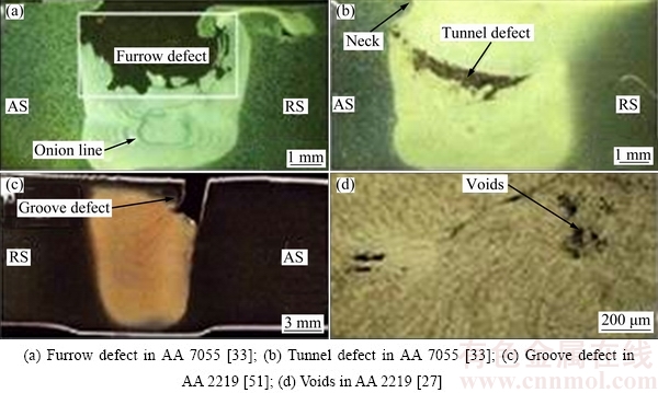
Fig. 15 Welding defects in UFSW
Studies have also revealed defects at too high welding speed in the SZ [33,51]. At high welding speed, tunnel defect (see Fig. 15(b)) is observed in AA 7055 [33] and grove defect (see Fig. 15(c)) is observed in AA 2219 in UFSW [51]. Plasticized material gets cooled down rapidly at high welding speed in water before filling the weld completely leading to tunnel defect. Tunnel defects are also observed in the SZ of the joints at the AS produced using straight and taper cylindrical tools due to insufficient frictional heat in AA 2519 T-87 [34].
S line feature (see Fig. 10(b)) is also observed in the SZ of AA 7055 during FSW [38,69] and UFSW of AA 7050 [73]. The ����S line���� is a defect which is formed due to breaking up of oxide layer due to insufficient stirring of the material. When welding is done in water, the atmospheric oxidation of the plate is prevented leading to elimination of S line defect.
5 Properties
5.1 Residual stress
FSW involves complex clamping and high clamping force for holding the welding plates. The firm clamping in FSW/UFSW exerts large amount of restraint upon the welding plates. During cooling, these restraints hamper the contraction of the SZ and HAZ, thus resulting in residual stresses (RSS). Moreover, cooling media (air, water) play a significant effect on RSS due to their intense effect on thermal cycle. Thus, distribution of residual stress is related to thermal cycle and restraint intensity. Both thermal and mechanical RSS are induced in FSW/UFSW, which can be tensile or compressive [69,94,95]. As RSS causes significant effect on the post weld mechanical properties, various techniques [96-100] have been acquired for measuring RSS in different processes. The RSS induced by FSW have been obtained by various destructive and non-destructive techniques such as X-ray diffraction [96-98], hole-drilling [99], and ultrasonic [100]. Ultrasonic technique offers rich advantages over the other methods including non- destructive testing, cheap equipments, short acquisition time and portable measurement setup. Generally, the RSS is higher on the AS in comparison to the RS due to high peak temperature and severe plastic deformation on AS. RSS are also larger in the longitudinal direction than that in the transverse direction [95]. Furthermore, some studies also deal with the effect of water on the extent of RSS encountered during the FSW as water (cooling medium) plays significant effect on RSS due to its deep effect on temperature cycles. UFSW can reduce the RSS as compared to FSW [69,95]. Cooling with water can decrease the longitudinal RSS up to 82% in the SZ compared to air [95]. Water cooling can also reverse the nature of the RSS developed during the welding. In an investigation by ZHAO et al [69], FSW joint showed tensile stress whereas compressive stress was found in the joint of UFSW. Residual compressive stress can improve the fatigue strength of the joints. UFSW creates mild and low thermal cycle and smooth temperature gradient than FSW, thus reducing the RSS of the joint.
5.2 Distortion
Being a solid-state welding process, low peak temperature and temperature gradient are involved in FSW process as compared to FW but still temperature increase at local area causes plastic strain in weld. The primary cause of distortion is the plastic strain that is not fully recovered during FSW. Manufacturing, assembling and application of structure are affected greatly by the welding distortion, so its examination is pivotal for FSW technology. Earlier researchers used to denote FSW as a non distortion method as the distortion was not significant in earlier studies [101]. Today, it is widely believed that distortion occurs during FSW and AA sheets possess distortion if they are welded by FSW [102,103]. Negligible studies have been reported on distortion in UFSW. Distortion profiles of the S275 plates welded with FSW in air and water were analysed by BAILLIE et al [89]. A submerged arc welded (SAW) DH36 steel plate was also analysed for highlighting the variation in distortion profile. The results showed less distortion in FSW plate in comparison to SAW plate. Also, the distortion was the least in UFSW due to high heat dissipation capacity of water which reduces thermal stresses in the material. The difference in distortion between the SAW and FSW plates was due to large clamping forces and high degree of restraint involved during FSW. These restraints avoid movement of the plate during welding, reducing the distortion. Moreover, low thermal stresses associated with FSW process in comparison to the SAW also resulted in reduced distortion.
5.3 Hardness
AAs are divided into two categories, i.e. heat- treatable (precipitation hardened) AAs and non heat- treatable (solid-solution hardened) AAs [104]. Numerous investigations have shown that hardness distribution is different for heat-treatable and non heat-treatable alloys in FSW.
In heat-treatable AAs, FSW/UFSW generally creates a softened area in the weld region. This is due to coarsening and dissolution of strengthening precipitates during FSW/UFSW [30,43,70,92,105]. The micro- hardness distributions of the joints of AA 2219 showed that the softening region is created in both FSW and UFSW joints [30]. AA 2017 with ultrafine grained (UFG) structure was produced by using equal channel angular processing (ECAP) after which they were joined by means of UFSW by WANG et al [43]. The result revealed softening of the UFSW joint compared with the UFG based material. Similar softening behavior was also observed in spray formed Al-Zn-Mg-Cu alloy in FSW and UFSW joints [71].
Cooling media also affect the hardness distribution across the weld. Large number of investigation has shown strength improvement in minimum hardness location using UFSW, leading to high hardness in UFSW in comparison to FSW [26,30,73,71]. The micro- hardness distributions of the joints of AA 2219 showed ��W-type�� hardness profile and the minimum hardness in the HAZ during FSW on the AS whereas in UFSW softening area is diminished significantly and the minimum hardness location (MHL) is changed lying on the interface between WNZ and TMAZ on AS and RS, as can be seen in Fig. 16(a) [30]. High dislocation density, enhanced solid solution strengthening effect and grain refinement due to water cooling lead to the increase of hardness of MHL. Identical results were said by WANG et al [71] in UFSW of spray formed Al-Zn-Mg-Cu alloy. Some researchers also suggested that the hardness improvement in HAZ is due to reducing of precipitate coarsening and the narrowing of PFZ induced by varying thermal cycles under water cooling effect [43,71]. ��W-type�� hardness profile was also observed by ZHAO et al [69] in FSW of AA7055. Minimum hardness was observed in TMAZ of the FSW joint but contrastingly minimum hardness was improved in UFSW eliminating the distinct low value area showing uniform hardness profile, as can be seen in Fig. 16(b) [69]. Similar results were also observed in AA 2519-T87 [26]. Thus, it is observed that in heat- treatable AAs, generally minimum hardness is located in the HAZ or TMAZ of the AS in FSW, but contrary to this in UFSW, the minimum hardness location gets shifted to SZ or SZ/TMAZ of AS/RS and softening region is also narrowed showing strength improvement in minimum hardness location. This hardness/strength improvement in heat-treatable AAs depends on precipitate distribution, dislocation density, grain size and solid solution [27,30,105,106], among which precipitate distribution has more effect than others [51,70,85,107].

Fig. 16 Microhardness distribution in different zones during FSW and UFSW
Hardness distribution is also affected by welding parameters, i.e. rotational speed, welding speed, and probe profile. In UFSW of AA 2219, it was observed that increasing tool rotation speed up to a certain limit improved the hardness of the joint due to increase in strain hardening effect (as shown in Fig. 17) [27]. When the rotation speed is too low or too high, the hardness minimum is relatively low because of inadequate tool stirring or excess heat input, as observed in AA2219 [27]. Moreover, with increasing rotational speed, softening width increases and minimum hardness location (MHL) of the joint also moves outward from the weld centre, as shown in Fig. 17(a). Generally, hardness in SZ also gets increased with increase in rotational speed [27]. With increasing welding speed, the softening region is gradually narrowed and the MHL of the joint moves in the direction of the weld centre, as observed in AA 2014 [87] and AA 2219 [51]. Also with increase in welding speed, hardness value in MHL is improved due to weakening of precipitate deterioration level as observed in AA 2014 [87] and AA2219 shown in Fig. 17(b) [51] and solid solution strengthening as observed in AA 2519-T87 [52]. Different probe profile also leads to change in microhardness value. Increased hardness is obtained in threaded profile in comparison to featureless (straight and taper cylindrical) probe profile [34]. Plain and featureless surface does not allow intensive deformation and thus proper stirring and mixing is not met in the welded region. The threaded profile offers more friction over the softened material and causes intensive deformation of material. Thus, proper mixing and stirring is achieved, leading to refine grain structure and improvement in hardness.
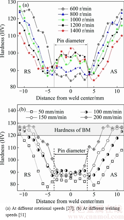
Fig. 17 Variation in hardness of UFSW joints of AA 2219
The hardness profile in non heat-treatable alloys is generally related to the grain size in FSW/UFSW [57,72, 108,109]. These AAs generally do not result in softening in the welds [57,107]. It is also observed that hardness tends to increase as the distance from the top surface increases. This is due to large heat at the top surface leading to more grain growth [108,109]. It is also reported that water as a cooling medium leads to improvement in the minimum hardness of the joint in non heat-treatable AAs also as compared to air cooling [57,72]. As the cooling rate of water is very high, refined grains are formed due to low peak temperature resulting in higher hardness in UFSW samples.
5.4 Mechanical properties
Due to intensive deformation of the material in FSW/UFSW, different microstructural changes occur in different regions of FSW. These microstructural changes lead to enormous alteration in post welding mechanical properties.
5.4.1 Strength and ductility
The tensile behavior is significantly affected by the stirring, heating and cooling conditions in the FSW/ UFSW process [30,33,51,56,70]. It is also believed that nonuniform microstructure across friction stir welds also causes variations in yield and ultimate tensile strength (UTS) and ductility [51,56,70]. Tensile strength is directly related to the hardness of the joint.
It is widely reported that cooling media (air, water) play significant role in improving the tensile properties of the joint produced in FSW [30,33,70,110]. It is observed that the tensile properties of underwater friction stir welds (UFSWs) are higher than those of normal friction stir welds (FSWs) [27,29,34,40,43,69]. Various reasons lead to improvement in tensile properties of the joints in UFSW. Tensile properties of the AA 2219 were studied by LIU et al [30] and ZHANG et al [70] based on cooling media, i.e. air and water. They reported increased tensile strength in UFSW joint. The joint efficiency in UFSW was 79% greater than that of base metal in FSW (see Fig. 18(a)). The refined grain structure and high- density dislocation lead to increase in tensile strength. Equivalent outcome had been additionally observed by WANG et al [38] in UFSW of AA7055. They reported 15% increase in tensile strength in water cooling environment as compared to air due to improved thermal cycle resulting in solid solution strengthening (see Fig. 18(b)). KISHTA and DARRAS [57] studied the tensile properties of non heat-treatable AA 5083 in air and water cooling environment. They also reported an increase in tensile strength in UFSW with strength reaching nearly that of the base material. The improvement in tensile strength was attributed to microstructural changes (size of the grain, orientation, void formation, etc) resulting from low peak thermal boundaries. Thickness level also affects the tensile properties of the material. Tensile specimens cut normal to the direction of the welding and segmented into three portions (top, middle and bottom) in the thickness direction were investigated for tensile strength in AA 2219 in air cooling and water cooling [110]. The highest strength exhibited at the top surface and the lowest strength was observed at the bottom surface with the middle surface lying in-between these values in FSW and UFSW. Additional strength was also found in UFSW due to reduction of the precipitate coarsening level and widening of PFZ due to low peak temperature. Furthermore, different results are obtained depending on whether the tensile testing is performed longitudinally or transversely to the weld. Transverse and longitudinal tensile tests were performed on S275 steel plate in FSW and UFSW for assessing tensile strength [89]. The results produced considerably higher strength (mean average YS and UTS) in the longitudinal tensile tests than in the transverse tensile tests. Grain refinement in the SZ leads to superior strength in longitudinal direction. Thus, it is obtained that the controlled temperature profiles [30,70], lower precipitate deterioration [51,110], refined grain structure [30,57,70,89], high density dislocation [30,70] and solid solution strengthening [38] lead to increase in tensile strength in water cooling atmosphere.
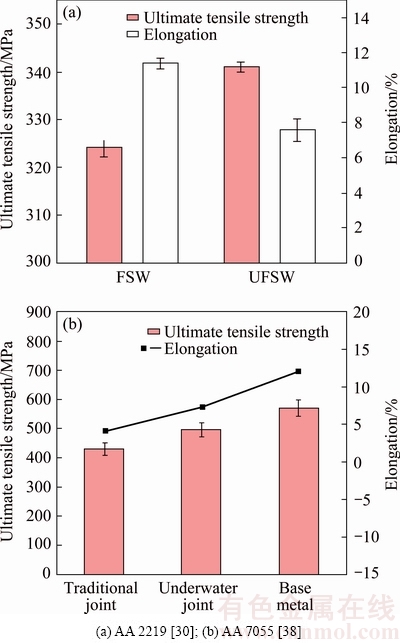
Fig. 18 Tensile properties of joint during FSW and UFSW
Frictional heating and stirring condition due to changes in welding speed [51,52], rotational speed [27,49,56,57] and plunge depth [56] also leads to changes in tensile strength.
Tensile strength rises with increment in the tool rotational speed [27,49,56,57]. In UFSW of AA 2219, it was observed that increasing tool rotational speed up to a certain limit improved the tensile strength of the joint due to increase in strain hardening effect and further increment in rotational speed deteriorates the joint properties due to excessive heat input [27], as shown in Fig. 19(a). The tensile strength tends to be low at less rotational speed owing to inadequate tool stirring action [56]. Too high rotational speed decreases the tensile strength due to turbulent metal flow owing to high heat input resulting in void formations [27]. Tensile strength also increases with increase in welding speed due to adequate heat and stirring of the material [51,52]. Too low welding speed increases the amount of heat into the weld causing decrease in tensile strength. Too high welding speed leads to insufficient heat and stirring of the material resulting in deterioration in tensile strength leading to defects [51,52]. The variation of tensile properties with welding speed is shown in Fig. 19(b).
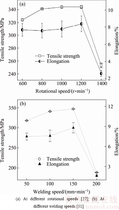
Fig. 19 Variation in tensile properties of UFSW joints of AA 2219
Tensile strength is less affected by the changes in plunge depth [56]. Increasing plunge depth enhances forging action and the material mixing leading to increase in tensile strength. If in case plunge depth is too large, increased frictional heat leads to lowering of tensile properties due to deterioration of the strengthening precipitates.
Ductility is another important parameter governing the mechanical properties of the weld. It is defined as the elongation resulted from tensile test and is calculated as maximum elongation of gage length divided by original length. Plastic deformation ability of the feeble region of the joint is determined by elongation [70,111]. Generally, high elongation is observed in UFSW as compared to FSW (see Fig. 18(b)) [38,57]. The improvement in the elongation in UFSW is mainly due to the limited overaging of finely dispersed second-phase particles caused by the FSW [38]. Further decrease in dislocation density also leads to improvement in ductility of the joint [57]. Sometimes, low ductility is also observed in UFSW in welding of AA 2219 (see Fig. 18(a)) [30]. The reduction in elongation is due to weak plastic deformation induced by high dislocation density and narrowing of the softening region due to integral cooling effect.
The variation in elongation with change in welding parameter is generally similar to that in tensile strength. The elongation varies slightly with rotational speed and welding speed and increases with increasing rotational speed and welding speed [27,51,52]. Variation of tensile properties with rotational and welding speed in AA 2219 is shown in Fig. 19.
Fracture is the separation of the material below the melting point temperature owing to stress. The fracture position of any welded joint denotes the weakest part of the joint [111]. The fracture locations of the joints are reliant on the hardness distributions and the weld defects of the joints [27,51,52,70,112].
For heat-treatable alloys, irrespective of the heat treatment condition, fracture normally takes place at the SZ [69,71], SZ/TMAZ boundary [30,70,51,52] in UFSW and near SZ [69,71], at or close to the HAZ/ TMAZ boundary [30,70,71,52] in FSW. Unlike FSW, in UFSW the failure location shifts towards weld centre due to improved microstructure and mechanical properties (hardness and strength) in low hardness region owing to cooling effect of water [30,70,71,110]. The fracture takes place generally at the AS [30,71,69] in FSW/UFSW.
In AA 2219, the FSW joint fractured in the HAZ near the TMAZ/HAZ interface on the AS while UFSW joint fractured at the boundary of SZ/TMAZ on AS (see Fig. 20) showing improvement in strength in the HAZ [30,70]. Comparable examination was obtained by ZHANG et al [70] showing shifting of fracture location to SZ/TMAZ interface indicating hardness improvement in HAZ due to water cooling. Similar results were also observed in AA 2519-T87 where the fracture location shifted to SZ/TMAZ interface from TMAZ during UFSW but the fracture took place at the RS [52].
WANG et al [71] and ZHAO et al [69] reported tensile fracture near the SZ at AS in AA7055 in FSW which was shifted to centre of SZ in UFSW.
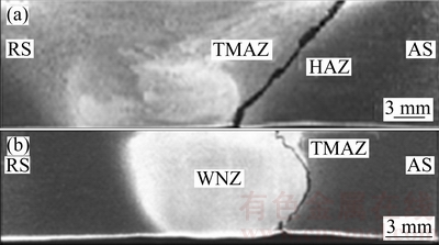
Fig. 20 Fracture locations in AA 2219 during FSW (a) and UFSW (b) [30]
Fracture locations of AA2219 at three different layers perpendicular to thickness direction in FSW and UFSW were investigated by LIU et al [110]. It was found that FSW joint fractured in the HAZ in all the three layers whereas in UFSW fracture location moved to periphery of the sample in SZ under all the conditions. This shows that even the middle layer is not in direct contact of the water, still the weakest locations of the joint are shifted in the direction of the weld center by the cooling action of water.
Rotational and welding speed also affects the fracture location. The joints welded at different rotational speeds generally fracture corresponding to the lower hardness region i.e. SZ, TMAZ and HAZ [27,49]. Sometimes, fracture takes place in a region where defects are formed [27]. Similarly, LIU et al [51] reported that fracture location is significantly affected by change in welding speed. During UFSW of AA 2219, it was observed that when welding speed was low the fractured position was in HAZ on the RS. Increase in welding speed shifted the fracture position to TMAZ on the AS.
Generally, two fracture modes, i.e. ductile or brittle, are associated with a material depending upon the ability of a material to withstand deformation prior to fracture [34,59]. Different fracture features are observed in FSW and UFSW [27,30,34,52,69,71]. The mode of failure is generally a ductile shear failure [34,52]. LIU et al [30] reported large dimples in FSW indicating extensive plastic deformation contrary to UFSW where dimple feature becomes ambiguous suggesting a decrease of plastic deformation level in AA 2219. The fracture feature of AA 2219 in FSW/UFSW is shown in Fig. 21. Similarly, WANG et al [71] observed fracture feature of FSW joint having typical cleavage characters showing large and small dimples while the UFSW fracture joint has mixed-rupture characteristics of quasi-cleavage with tiny dimples in AA 7055. SABRI et al [34,52] also observed tiny dimples in both water and air cooling orienting at 45�� towards the loading direction in AA 2519. Presence of dimples suggested joint failing in ductile mode.
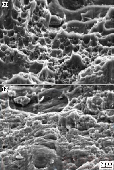
Fig. 21 Fracture features of AA 2219 during FSW (a) and UFSW (b) [30]
5.4.2 Fracture toughness
Fracture toughness mainly describes the ability of a material that contains cracks to resist fracture. For propagation of a prior existing flaw, it provides an indication of the quantity of stress required. Flaws are found in all the welded components as cracks, voids, inclusions, weld defects, etc. These flaws are not completely avoidable and should be repaired before the weld is put in practice. By taking into account the wide application of FSW, there is a vital need for suitable assessment of the fracture behavior of the FS welds. Parameters like crack tip intensity factors (K) for linear elastic loading, and the J integral or the crack opening displacement (CTOD) for elastic�Cplastic loading are the most common in assessing fracture toughness [113]. Several examinations have been conducted to estimate the effect of FSW on the fracture toughness [114,115]. Surprisingly, no examination on fracture toughness had been reported in literature pertaining to UFSW. This mechanical property should be addressed in UFSW also as it measures crack propagation.
5.4.3 Impact toughness
Impact toughness (impact strength) is defined as how much impact energy a weld takes before it cracks, generally when stress/strain has been applied to it rapidly. The impact strength of a material can be measured by using a Charpy or Izod test. In FSW, impact strength had been measured by various researchers [116-119]. From the reviewed literature, it is found that in UFSW impact toughness is only assessed by BAILLIE et al [89]. Charpy impact toughness of S275 steel was measured at different temperature in both air and water cooling according to BS EN ISO 148-1: 2010. The specimens were designed normal to the weld centre line with different notch positions from the weld centre. As UFSW is credited with the faster cooling rate, it prevented the material from fully recrystallizing leading to reduction in impact toughness.
5.4.4 Fatigue
Aerospace structure, marine structure, transport vehicles etc are highly subjected to cyclic stress and strains resulting in fatigue and cyclic deformation of the parts. So, it is vital to investigate the fatigue deformation characteristics of the UFSW joints owing to its broad application in marine and offshore structures in order to assure the structural reliability and safe application. There are various investigations reported on the fatigue properties of FSW welds. These studies are focused generally on the fatigue life [120-122] and crack growth [123-125], with limited studies on the low-cycle fatigue (LCF) behavior of FSW welds [126,127]. In UFSW only limited studies have been reported on fatigue behavior [89,128].
Strain-controlled low-cycle fatigue tests were executed on a FSWed AA 2219-T62 with varying process parameters and cooling media (air and water) by XU et al [128]. They observed that the fatigue life of FSWed joints with water cooling increased in comparison with air cooling at a given total strain amplitude. With the increase in the rotational speed, the cyclic stress amplitude is increased and plastic strain amplitude and fatigue lifetime are slightly decreased but they are nearly independent on the rotational speed. Compared with air cooling, the FSWed joints with water cooling had higher stress amplitude and fatigue life. At stress level of 90% of the measured yield strength, the low cycle fatigue cycle was performed by BAILLIE et al [89]. Statistical results (log-normal distributions and pooled data) showed no momentous difference in the fatigue cycle of the water and air welds.
6 Corrosion characteristics
Due to intensive deformation of the material in FSW/UFSW, different microstructural changes occur in different regions of FSW such as different grain sizes and dislocation density, coarse precipitates and PFZs and precipitate size and distribution. These microstructural changes lead to enormous alteration in corrosion properties in different zones. AAs are generally susceptible to intergranular corrosion (IGC) and exfoliation corrosion (EC) [129]. Various studies pertaining to corrosion susceptibility are conducted in FSW [130-133] but in UFSW it is still a potential area of research.
Corrosion behavior of spray formed AA 7055 was investigated by WANG et al [38]. It was observed that UFSW joint showed typical IGC pattern and same corrosion degree (rank 4) as the base metal. No grain boundaries were observed in the corrosion path of UFSWed joint unlike base metal where the grain boundary was revealed in corrosion paths. Corrosion degree of rank 3 was observed in FSW joint. Further, in first 24 h, UFSWed joint was more sensitive to EC showing large bumps in comparison to base metal and FSW joint where blisters and pits were observed on the surface. In past 48 h, corrosion rate of UFSWed joint was slow in comparison to FSW joint and base metal and got only 3 level leaps in level of corrosion. Additionally, Tafel curves showed that UFSWed joint had low corrosion current and more negative potential corrosion than base metal and FSW joint. It was found that low potential MgZn2 phase clustering was the main reason for highly corroded base metal. In FSW, due to larger heat, the MgZn2 was displaced by unevenly distributed MgCu2, but the uneven distribution MgCu2 causes PFZs leading to corrosion. Under UFSW, the MgZn2 got stirred into the grains blocking the grain boundaries and paths of corrosion leading to decrease in corrosion rate.
7 Dissimilar welding
The advancement of FSW in successful welding of AAs has encouraged its application to weld different material and alloys (magnesium, copper, etc). However, due to difference in chemical and physical properties, the welding of dissimilar materials is not easy. In this regard, key issues associated with dissimilar welding of different materials are addressed in this section.
7.1 Aluminum�Cmagnesium
High strength with low weight and high corrosion resistance characteristics of AAs offer them suitability for use in various aerospace, automotive and marine applications as structural materials [134]. Magnesium alloys have density as low as two-thirds than AAs. They are the lightest structural material and are gaining wide application in aerospace, automobile and ship yard [135]. So, in order to gain the advantages of properties of both Al and Mg, welds amid Al-Mg alloys are fabricated. High specific strength and high anticorrosion properties of these materials allow their uses in transportation and electronic industries. Welding of these alloys with FW techniques offers difficulty due to pores, cracks and brittle formed in the joint leading to deterioration of mechanical properties [2]. Solid welding process FSW offers advantage above FW techniques in welding of Al and Mg alloys due to welded joints providing high mechanical properties with no defects [136]. However, high peak temperature developed during the welding of Al-Mg has resulted in liquation and formation of brittle intermetallic compound, which consequently leads to deterioration of mechanical properties in FSW [59,75, 137,138]. Thus, the key problem is to control the liquation and growth of IMCs in FSW of Al-Mg alloy. In order to resolve these issues, a method that enhances the cooling rate and lowers the peak temperature can offer improved properties of the joint in FSW. In recent years, improved strength was obtained through the use of FSW done in water as compared to air [59,75,76,139]. Water due to its high cooling rate and high heat absorption capacity helps in lowering the peak temperature of the weld leading to lowering of the IMCs.
Temperature profiles of AA 5083-AZ 31C-O Mg alloy and AA 6013-AZ31 Mg alloy were investigated by MOFID et al [75 ] and ZHO et al [59], respectively. They found that the peak temperature in UFSW is found to be significantly lower than that in FSW. Moreover, smaller temperature gradient was observed in UFSW compared to FSW [59]. Furthermore, higher temperature was observed in the AS compared to RS [75].
Macro and micro features were also investigated by some researchers [59,75,76,139]. Smoother and brighter surface and less intermixing between Al and Mg alloys was observed in UFSW as compared to FSW, as shown in Figs. 22(a) and (b) [75,76]. This is due to lower temperature and high cooling rate associated with the UFSW. The microstructural features of the dissimilar Al and Mg alloys showed mixed structure and complex intercalated flow patterns. Mixed structures showed lamellar shear bands consisting of recrystallized AA or Mg alloy [76]. Interface of AA/Mg alloy also consists of an intermetallic (IM) layer. The layer is found to be much thinner in UFSW in comparison to FSW (see Figs. 22(c) and (d)) [75,76].
Microhardness profile in UFSW revealed increased hardness in SZ but lower than that in FSW welded sample due to less amount of IMC [59,75].
Improved tensile strength is observed in UFSW as compared to FSW having joint efficiency of approx 65% of the base metal whereas the ductility is low due to IMC at the interface [59,76].
Cleavage like fracture feature is observed in UFSW indicating brittle fracture mechanism. IMCs like Al3Mg2 and Mg17Al12 were noticed at the interface on Mg and Al side [59,76]. It is also seen that less amount of IMC was formed during UFSW as compared to normal FSW leading to elimination of weld crack observed in FSW [75].
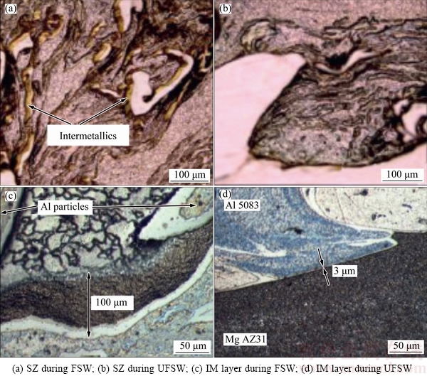
Fig. 22 Microstructures of Al 5083-Mg AZ31 [75,76]
7.2 Aluminum-copper
Copper has been extensively used for producing engineering parts such as electrical elements, and switchgear due to its excellent features like high corrosion resistance, thermal and electrical conductivity [140]. Aluminum and its alloys are lighter in weight having high strength, and can easily be fabricated. Bimetallic joints of Al/Cu are used in a number of electrical and thermal applications [141]. To meet the demands from the electric power industry, the bolted Al-Cu joints have been substituted by welds [142]. Because of the presence of large variation in melting points, brittle IMCs and crack formation, it is difficult to produce high quality Al-Cu dissimilar joint by FW techniques [143]. Due to these reasons, the solid-state joining methods, such as FSW, become more popular. In FSW, the peak temperature is lower than the melting point of the material, so it offers outstanding ability to weld dissimilar metals [143-146]. Despite this, it is found that IMCs at the interface cause major problem in FSW of dissimilar Al-Cu metals [147-149]. These IMCs reduce the strength, toughness and increase the electrical resistivity in Al-Cu joints. Peak temperature and incubation time are the factors that determine the growth and development of IMCs. Controlled peak temperature and small incubation time could reduce the quantity of the brittle IMCs. This problem can be solved if the process is conducted in water, because the water cooling enhances the heat dissipation affecting temperature distribution in the weld. ZHANG et al [58] through XRD analysis mentioned IMCs such as CuAl2, Cu9Al4 along with some quantity of Al and Cu in FSW/UFSW. However, for UFSW, the amount of IMCs was limited. The melting point of Al-Cu eutectic or some of the Al�CCu hypo-eutectic and hyper-eutectic alloys is 825 K [145]. In FSW, due to high plastic deformation and high frictional heat, the peak temperature of Al/Cu interface reaches more than the melting point of the Al-Cu eutectic, leading to the growth and formation of IMCs. However, for the UFSW, the water cooling significantly reduces the peak temperature and also speeds up the cooling rate leading to limitation of IMCs. Moreover, UFSW can prevent the thickening of the Al-Cu diffusion interlayer. Thin diffusion layer indicates that the amount of brittle IMCs has been decreased leading to effective joining.
8 Conclusions and future suggestions
This review article outlines the current status and understanding of the UFSW mostly in AAs and consequently improvement of UFSW over FSW in terms of joint quality, microstructure evolved and mechanical properties. On the basis of the comprehensive literature review, following conclusions are drawn:
1) UFSW uses water as a cooling medium which reduces temperature and restricts the coarsening or dissolution of the precipitates leading to enhanced mechanical properties of the joint.
2) For producing sound and defect-free welds, proper tool geometry and welding parameters are required. It is observed that threaded pin and concave shoulder with groove bottom yield a defect-free joint in UFSW. Due to high plastic deformation and shearing of material, threaded probe profile yields sound joints. Concave shoulder due to its design helps in directing the material flow to the centre near the probe providing advantage in its use over flat shoulder.
3) Rotational speed and welding speed are the dominating factors influencing the weld formation. At too low or too high rotational speed and welding speed can result in poor joint properties. As compared to FSW, UFSW requires higher rotational speed and welding speed for producing sound joints.
4) Material flow and temperature generation are governed by tool geometry and welding parameters. In UFSW, material flow within the weld is very complex and poorly understood.
5) The temperature distribution in FSW/UFSW directly influences the mechanical properties and microstructure (grain size, coarsening of precipitates) of the joints. Low temperature, less temperature gradient and high cooling rate associated with the UFSW resulted in fine grains, high dislocation density and limited precipitate dissolution and coarsening leading to improved mechanical properties as compared to FSW.
6) In addition to AAs, UFSW has been effectively used to join dissimilar materials like Al-Cu and Al-Mg as decreased amount of brittle IMCs are formed due to low peak temperature and small incubation time in UFSW.
Despite numerous advantages of UFSW over FSW, considerable interest has not been shown in UFSW. Some of the future research works which can be carried out are suggested below:
1) Material flow pattern is not understood properly in UFSW. Various new analytical methods and computational models should be incorporated for understanding the flow of material properly in UFSW.
2) Geometry and wear behavior of the tool are very important aspects and need deep understanding and therefore computational procedure can be used to optimize the tool geometry.
3) Very few holistic studies on different forces encountered during the UFSW are reported in the literature. Attempts need to be made to measure these forces.
4) Welding of dissimilar materials in UFSW is limited and requires detailed and methodical investigation.
5) Considerable scope exists for analyzing heat input, heat balance, flow stress on both sides, i.e. advancing/retreating and top/bottom sides.
6) Surprisingly, no examination on fracture toughness has been reported in literature pertaining to UFSW. By taking into account the wide application of UFSW, there is a need for suitable assessment of the fracture behavior of the UFSW joints.
7) No systematic information on the tool material is available. Studies should be incorporated for selection of cost effective FSW/UFSW tools for improving performance of the joints generally in dissimilar welding.
8) Negligible information on fatigue deformation and corrosion properties of UFSW is available. These properties need deep and careful assessment.
References
[1] PRAVEEN P, YARLAGADDA P K D V. Meeting challenges in welding of aluminum alloys through pulse gas metal arc welding [J]. Journal of Materials Processing Technology, 2005, 164-165: 1106-1112.
[2] LIU P, LI Y, GENG H, WANG J. Microstructure characteristics in TIG welded joint of Mg/Al dissimilar materials [J]. Materials Letters, 2007, 61(6): 1288-1291.
[3] THOMAS W M, NICHOLAS E D, NEEDHAM J C, MURCH M G, SMITH P T, DAWES C J. Friction stir butt welding: UK9125978 [P]. 1991-12-06.
[4] GUERRA M, SCHMIDT C, MCCLURE L C, MURR L E, NUNES A C. Flow patterns during friction stir welding [J]. Materials Characterization, 2003, 49: 95-101.
[5] RHODES C G, MAHONEY M W, BINGEL W H, SPURLING R A, BAMPTON C C. Effects of friction stir welding on microstructure of 7075 aluminum [J]. Scripta Materialia, 1997, 36(1): 69-75.
[6] ZHAO J, JIANG F, JIAN H G, WEN K, JIANG L, CHEN X B. Comparative investigation of tungsten inert gas and friction stir welding characteristics of Al-Mg-Sc alloy plates [J]. Materials and Design, 2010, 31: 306-311.
[7] CAVALIERE P, CABIBBO M, PANELLA F, SQUILLACE A. 2198 Al-Li plates jointed by friction stir welding: Mechanical and microstructural behaviour [J]. Materials and Design, 2009, 30: 3622-3631.
[8] THOMAS W M, NICHOLAS E D. Friction stir welding for the transportation industries [J]. Materials and Design, 1997, 18: 269-273.
[9] SIDDIQUEE A N, PANDEY S. Experimental investigation on deformation and wear of WC tool during friction stir welding (FSW) of stainless steel [J]. International Journal of Advanced Manufacturing Technology, 2014, 73: 479-486.
[10] MISHRA R S, MA Z Y. Friction stir welding and processing [J]. Mater Science and Engineering A, 2005, 50: 1-78.
[11] CHO J H, HAN S H, LEE C G. Cooling effect on microstructure and mechanical properties during friction stir welding of Al-Mg-Si aluminum alloys [J]. Materials Letters, 2016, 180: 157-161.
[12] SIDDIQUEE A N, PANDEY S, KHAN N Z. Friction stir welding of austenitic stainless steel: A study on microstructure and effect of parameters on tensile strength [J]. Materials Today: Proceedings, 2015, 2(4-5): 1388-1397.
[13] SIDHAR H, MARTINEZ N Y, MISHRA R S, SILVANUS J. Friction stir welding of Al-Mg-Li 1424 alloy [J]. Materials & Design, 2016, 106: 146-152.
[14] WOO W, BALOGH L,  T, CHOO H, FENG Z. Grain structure and dislocation density measurements in a friction-stir welded aluminum alloy using X-ray peak profile analysis [J]. Material Science and Engineering A, 2008, 498(1-2): 308-313.
[15] LIU G, MURR L E, NIOU C S, MCCLURE J C, VEGA F R. Micro structural aspects of the friction-stir welding of 6061-T6 aluminum [J]. Scripta Materialia, 1997, 37: 355-361.
[16] JATA K V, SEMIATIN S L. Continuous dynamic recrystallization during friction stir welding of high strength aluminum alloys [J]. Scripta Materialia, 2000, 43: 743-749.
[17] BENAVIDES S, LI Y, MURR L E, BROWN D, MCCLURE J C. Low-temperature friction-stir welding of 2024 aluminum [J]. Scripta Materialia, 1999, 41: 809-815.
[18] LIU H J, FUJII H, MAEDA M, NOGI K. Tensile properties and fracture locations of friction stir welded joints of 6061-T6 aluminum alloy [J]. Materials Science Letters, 2003, 22: 1061-1063.
[19] BAESLACK W A, JATA K V, LIENERT T J. Structure, properties and fracture of friction stir welds in a high-temperature Al-8.5Fe-1.3V-1.7Si alloy [J]. Materials Science, 2006, 41: 2939-2951.
[20] CABIBBO M, MCQUEEN H J, EVANGELISTA E, SPIGARELLI S, PAOLA M D, FALCHERO A. Microstructure and mechanical property studies of AA6056 friction stir welded plate [J]. Materials Science and Engineering A, 2007, 460-461: 86-94.
[21] FRATINI L, BUFFA G, SHIVPURI R. In-process heat treatments to improve FS-welded butt joints [J]. International Journal of Advanced Manufacturing Technology, 2009, 43: 664-70.
[22] SAKURADA D, KATOH K, TOKISUE H. Underwater friction welding of 6061 aluminum alloy [J]. Journal of Japan Institute of Light Metals, 2002, 52(1): 2-6.
[23] CLARK T D. An analysis of microstructure and corrosion resistance in underwater friction stir welded 304L stainless steel [D]. Provo: Brigham Young University, 2005.
[24] UPADHYAY P, REYNOLDS A P. Effects of thermal boundary conditions in friction stir welded AA7050-T7 sheets [J]. Materials Science and Engineering A, 2010, 527: 1537-1543.
[25] MOFID M A, ABDOLLAH-ZADEH A, GHAINI F M, GUR C H. Submerged friction-stir welding (SFSW) underwater and under liquid nitrogen: An improved method to join Al alloys to Mg alloys [J]. Metallurgical And Materials Transactions A, 2012, 43: 5106-5114.
[26] SABARI S S, MALARVIZHI S, BALASUBRAMANIAN V, REDDY G M. Experimental and numerical investigation on under-water friction stir welding of armour grade AA2519-T87 aluminium alloy [J]. Defence Technology, 2016 12: 324-333.
[27] ZHANG H J, LIU H J, YU L. Microstructure and mechanical properties as a function of rotation speed in underwater friction stir welded aluminum alloy joints [J]. Materials and Design, 2011, 32: 4402-4407.
[28] NELSON T W, STEEL R J, ARBEGAST W J. In situ thermal studies and post-weld mechanical properties of friction stir welds [J]. Science and Technology of Welding and Joining, 2003,8(4): 283-288.
[29] XUA W F, LIU J H, CHEN D L, LUAN G H, YAO J S. Improvements of strength and ductility in aluminum alloy joints via rapid cooling during friction stir welding [J]. Materials Science and Engineering A, 2012, 548: 89-98.
[30] LIU Hui-jie, ZHANG Hui-jie, HUANG Yong-xian, LEI Y. Mechanical properties of underwater friction stir welded 2219 aluminum alloy [J]. Transactions of Nonferrous Metals Society of China, 2010, 20: 1387-1391.
[31] LORRAIN O, FAVIER V, ZAHROUNI H, LAWRJANIEC D. Understanding the material flow path of friction stir welding process using unthreaded tool [J]. Journal of Material Processing Technology, 2010, 210: 603-609.
[32] HIRASAWA S, BADARINARAYAN H, OKAMOTO K, TOMIMURA T, KAWANAMI T. Analysis of effect of tool geometry on plastic flow during friction stir spot welding using particle using particle method [J]. Journal of Materials Processing Technology, 2010, 210(11): 1455-1463.
[33] WANG Q, ZHAO Z, ZHAO Y, YAN K, ZHANG H. The adjustment strategy of welding parameters for spray formed 7055 aluminum alloy underwater friction stir welding joint [J]. Materials and Design, 2015, 88: 1366-1376.
[34] SABARI S S, MALARVIZHI S, BALASUBRAMANIAN V, REDDY G. The effect of pin profiles on the microstructure and mechanical properties of underwater friction stir welded AA2519-T87 aluminium alloy [J]. International Journal of Mechanical and Materials Engineering, 2016, 11(5): 1-14.
[35] ELANGOVAN K, BALASUBRAMANIAN V. Influences of tool pin profile and tool shoulder diameter on the formation of friction stir processing zone in AA6061 aluminium alloy [J]. Materials and Design, 2008, 29(2): 362-373.
[36] ARORA A, DE A, DEBROY T. Toward optimum friction stir welding tool shoulder diameter [J]. Scripta Materialia, 2011, 64(1): 9-12.
[37] KHAN N Z, KHAN Z A, SIDDIQUEE A N. Effect of shoulder diameter to pin diameter (D/d) ratio on tensile strength of friction stir welded 6063 aluminium alloy [J]. Material Today Proceedings, 2015, 2(4-5): 1450-1457.
[38] WANG Q, ZHAO Y, YAN K, LU S. Corrosion behaviour of spray formed 7055 aluminum alloy joint welded by underwater friction stir welding [J]. Materials and Design, 2015, 68: 97-103.
[39] DAWES C J, THOMAS W M. Development of improved tool design for friction stir welding of aluminium [C]//Proceeding of International Conference on FSW. Thousand Oaks: TWI, 1999.
[40] BRINCKMANN S, STROMEBECK A, SCHILLING C, SANTOS J F, LOHWASSER D, KOCAK M. Mechanical and toughness properties of robotic-FSW repair welds in 6061-T6 aluminum alloy [C]//Proceeding 2nd International Conference on FSW. Gothenburg: TWI, 2000: 26-28.
[41] CEDERQVIST L, SORENSEN C D, REYNOLDS A P, OBERG T. Improved process stability during friction stir welding of 5 cm thick copper canisters through shoulder geometry and parameter studies [J]. Science and Technology of Welding and Joining, 2009, 14(2): 178-184.
[42] COLLIGAN K J, PICKENS J R. Friction stir welding of aluminium using a tapered shoulder tool [C]//Frictions Stir Welding and Processing III. San Francisco, California: TMS, 2005: 161-170.
[43] WANG Kuai-she, WU Jia-lei, WANG W, ZHOU Long-hai, LIN Zhao-xia, KONG Liang. Underwater friction stir welding of ultrafine grained 2017 aluminum alloy [J]. Journal of Central South University, 2012, 19: 2081-2085.
[44] SURESHA C N, RAJAPRAKASH B M, UPADHYA S. A study of the effect of tool pin profiles on tensile strength of welded joints produced using friction stir welding process [J]. Materials and Manufacturing Processes, 2011, 26: 1111-1116.
[45] PAPAHN H, BAHEMMAT P, HAGHPANAHI M, SOMMITSCH C. Study on governing parameters of thermal history during underwater friction stir welding [J]. International Journal of Advanced Manufacturing Technology, 2015, 78: 1101-1111.
[46] THOMAS W M, NICHLOAS E D, SMITH S D, Friction stir welding tool developments [C]//Proceeding Aluminum Automotive and Joining Sessions. Warrendale, Pennsylvania: TMS, 2001: 213-224.
[47] THOMAS W M, JOHNSON K I, WIESNER C S. Friction stir welding recent development in tool and process technologies [J]. Advanced Engineering Materials, 2003, 5(7): 485-490.
[48] SATO Y, URATA M, KOKAWA H. Parameters controlling microstructure and hardness during friction-stir welding of precipitation-hardenable aluminum alloy 6063 [J]. Metallurgical Materials Transaction A, 2002, 33(3): 625-635.
[49] SABARI S S, MALARVIZHI S, BALASUBRAMANIAN V. Characteristics of FSW and UWFSW joints of AA2519-T87 aluminium alloy: Effect of tool rotation speed [J]. Journal of Manufacturing Processes, 2016, 22: 278-289.
[50] SELLARS C M, MCTEGART W J. On the mechanism of hot deformation [J]. Acta Metallurgica, 1966, 14: 1136-1138.
[51] LIU Hui-jie, ZHANG Hui-jie, YU L. Effect of welding speed on microstructures and mechanical properties of underwater friction stir welded 2219 aluminum alloy [J]. Materials and Design, 2011, 32(3): 1548-1553.
[52] SABARI S S, MALARVIZHI S, BALASUBRAMANIAN V. Influences of tool traverse speed on tensile properties of air cooled and water cooled friction stir welded AA2519-T87 aluminium alloy joints [J]. Journal of Materials Processing Technology, 2016, 237: 286-300.
[53] PAYGANEH G H, MOSTAFA N B A, DADGAR ASL Y, GHASEMI F A, BOROUJENI M S. Effects of friction stir welding process parameters on appearance and strength of polypropylene composite welds [J]. International Journal of the Physical Sciences, 2011, 6(19): 4595-4601.
[54] HASSAN K A A, PRAGNELL P B, NORMAN A F, PRICE D A, WILLIAMS S W. Effect of welding parameters on nugget zone microstructure and properties in high-strength aluminium alloy friction stir welds [J]. Science and Technology of Welding and Joining, 2003, 8: 257-268.
[55] WAHID M A, SIDDIQUEE A N, KHAN Z A, ASJAD M. Friction stir welds of Al-Cu alloy: An investigation on effect of plunge depth [J]. Archive of Mechanical Engineering, 2016, 63(4): 619-634.
[56] ZHANG H, LIU H. Mathematical model and optimization for underwater friction stir welding of a heat-treatable aluminum alloy [J]. Materials and Design, 2013, 45: 206-211.
[57] KISHTA E E, DARRAS B. Experimental investigation of underwater friction-stir welding of 5083 marine-grade aluminum alloy [J]. Proceedings of the Institution of Mechanical Engineers, Part B: Journal of Engineering Manufacture, 2014, 230(3): 458-465.
[58] ZHANG J, SHEN Y, YAO X, XU H, LI B. Investigation on dissimilar underwater friction stir lap welding of 6061-T6 aluminum alloy to pure copper [J]. Materials and Design, 2014, 64: 74-80.
[59] ZHAO Y, JIANG S, YANG S, LU Z, YAN K. Influence of cooling conditions on joint properties and microstructures of aluminum and magnesium dissimilar alloys by friction stir welding [J]. International Journal of Advanced Manufacturing Technology, 2016, 83: 673-679.
[60] SEIDEL T U, REYNOLDS A P. Visualization of the material flow in AA2195 friction-stir welds using a marker insert technique [J]. Metallurgical and Materials Transaction, 2001, 32: 2879-2884.
[61] OUYANG J H, KOVACEVIC R. Material flow and microstructure in the friction stir butt welds of the same and dissimilar aluminum alloys [J]. Journal of Materials Engineering and Performance, 2002, 11: 51-63.
[62] CHEN Z W, PASANG T, QI Y. Shear flow and formation of nugget zone during friction stir welding of aluminium alloy 5083-O [J]. Materials Science and Engineering A, 2008, 474: 312-316.
[63] CHOWDHURY S M, CHEN D L, BHOLE S D, CAO X. Tensile properties of a friction stir welded magnesium alloy: Effect of pin tool thread orientation and weld pitch [J]. Materials Science and Engineering A, 2010, 527(21-22): 6064-6075.
[64] COLEGROVE P, SHERCLIFF H. Two-dimensional CFD modeling of flow round profiled FSW tooling [J]. Science and Technology of Welding and Joining, 2004, 9(6): 483-492.
[65] NUNES A C Jr. Aluminum 2001 [C]//DAS S K, KAUFMAN J G, LIENERT T J. Proc Aluminum Automotive and Joining Symposia. Warrendale, PA: TMS, 2001, 235.
[66] KE L, XING L, INDACOCHEA J E. Joining of advanced and specialty materials IV [C]//Materials Solution. Indiana: ASM International, 2002: 125-134.
[67] ARBEGAST W, JIN Z. Modeling friction stir joining as a metalworking process [C]//Hot Deformation of Aluminum Alloys III. San Diego, California: TMS, 2003.
[68] ZHANG H, LIU H. Characteristics and formation mechanisms of welding defects in underwater friction stir welded aluminum alloy [J] Metallography, Microstructure and Analysis, 2012, 1: 269-281.
[69] ZHAO Y, WANG Q, CHEN H, YAN K. Microstructure and mechanical properties of spray formed 7055 aluminum alloy by underwater friction stir welding [J]. Materials and Design, 2014, 56: 725-730.
[70] ZHANG H J, LIU H J, YU L. Effect of water cooling on the performances of friction stir welding heat-affected zone [J]. Journal of Materials Engineering and Performance, 2012, 21(7): 1182-1187.
[71] WANG Q, ZHAO Z, ZHAO Y, YAN K, LIU C, ZHANG H. The strengthening mechanism of spray forming Al-Zn-Mg-Cu alloy by underwater friction stir welding [J]. Materials and Design, 2016, 102: 91-99.
[72] HOSSEINI M, MANESH H D. Immersed friction stir welding of ultrafine grained accumulative roll-bonded al alloy [J]. Materials and Design, 2010, 31: 4786-4791.
[73] FU R D, SUN Z Q, SUN R C, LI Y, LIU H J, LIU L. Improvement of weld temperature distribution and mechanical properties of 7050 aluminum alloy butt joints by submerged friction stir welding [J]. Materials and Design, 2011, 32: 4825-4831.
[74] XUE P, XIAO B L, ZHANG Q, MA Z Y. Achieving friction stir welded pure copper joints with nearly equal strength to the parent metal via additional rapid cooling [J]. Scripta Materialia, 2011, 64: 1051-1054.
[75] MOFID M A, ABDOLLAH-ZADEH A, GHAINI F M. The effects of water cooling during dissimilar friction stir welding of Al alloy to Mg alloy [J]. Materials And Design, 2012, 36: 161-167.
[76] ZHAO Y, LU Z, YAN K, HUANG L. Microstructural characterizations and mechanical properties in underwater friction stir welding of aluminum and magnesium dissimilar alloys [J]. Materials and Design, 2014, 65: 675-681.
[77] FRATINI L, BUFFA G, SHIVPURI R. Mechanical and metallurgical effects of in process cooling during friction stir welding of AA7075-T6 butt joints [J]. Acta Materialia, 2010, 58(6): 2056-2067.
[78] ZHANG Hui-jie, LIU Hui-jie, YU L. Thermal modeling of underwater friction stir welding of high strength aluminum alloy [J]. Transactions of Nonferrous Metals Society of China, 2013, 23: 1114-1122.
[79] THREADGILL P L. Friction stir welds in aluminium alloys �C Preliminary microstructural assessment [J]. TWI Bulletin, 1997, 28: 30-33.
[80] THREADGILL P L, LEONARD A J. Macro and microstructural features of friction stir welds in various materials [R]. TWI members Report No. 693/1999. Abington, TWI, 1999.
[81] THREADGILL P L. Terminology in friction stir welding [J]. Science and Technology of Welding and Joining, 2007, 12: 357-360.
[82] American Welding Society, USA. Specifications for friction stir welding of aluminum alloys for aerospace applications. Standard D17.3: 200X [S]. 2006.
[83] KWON Y J, SHIGEMATSU I, SAITO N. Dissimilar friction stir welding between magnesium and aluminum alloys [J]. Materials Letters, 2008, 62: 3827-3829.
[84] PRANGNELL P B, HEASON C P. Grain structure formation during friction stir welding observed by the stop action technique [J]. Acta Materialia, 2005, 53: 3179-3192.
[85] LI B, SHEN Y. The investigation of abnormal particle-coarsening phenomena in friction stir repair weld of 2219-T6 aluminum alloy [J]. Materials and Design, 2011, 32: 3796-3802.
[86] ZHAO Y, ZHOU L, WANG Q, YAN K, ZOU J. Defects and tensile properties of 6013 aluminum alloy T-joints by friction stir welding [J]. Materials and Design, 2014, 57: 146-155.
[87] ZHANG Z, XIAO B L, MA Z Y. Influence of water cooling on microstructure and mechanical properties of friction stir welded 2014Al-T6 joints [J]. Materials Science and Engineering A, 2014, 614: 6-15.
[88] ZHANG Z, ZHANG H W. Numerical studies on the effect of transverse speed in friction stir welding [J]. Materials and Design, 2009, 30: 900-907.
[89] BAILLIE P, CAMPBELL S W, GALLOWAY A M, CATER S R, MCPHERSON N A. A comparison of double sided friction stir welding in air and underwater for 6 mm S275 steel plate [J]. International Journal of Chemical, Nuclear, Metallurgical and Materials Engineering, 2014, 8(8): 643-647.
[90] SAKAI T, MIURA H, YANG X. Ultrafine grain formation in face centered cubic metals during severe plastic deformation [J]. Materials Science and Engineering A, 2009, 499: 2-6.
[91] SUN Y, FUJII H, TAKADA Y, TSUJI N, NAKATA K, NOGI K. Effect of initial grain size on the joint properties of friction stir welded aluminium [J]. Materials Science and Engineering A, 2009, 527: 317-321.
[92] DE P S, MISHRA R S. Friction stir welding of precipitation strengthened aluminium alloys: Scope and challenges [J]. Science and Technology of Welding and Joining, 2011, 16: 343-347.
[93] KHAN N Z, SIDDIQUEE A N, KHAN Z A, SIHAB S K. Investigations on tunneling and kissing bond defects in FSW joints for dissimilar aluminum alloys [J]. Journal of Alloys and Compounds, 2015, 648: 360-367.
[94] KUMAR N, MISHRA R S, BAUMANN J A. Residual stresses in friction stir welding [M]. United Kingdom: Butterworth-Heinemann Ltd, 2013.
[95] PAPAHN H, BAHEMMAT P, HAGHPANAHI M. Effect of cooling media on residual stresses induced by a solid-state welding: underwater FSW [J]. International Journal of Advanced Manufacturing Technology, 2016, 83: 1003-1012.
[96] PEEL M, STEUWER A, PREUSS M, WITHERS P J. Microstructure, mechanical properties and residual stresses as a function of welding speed in aluminium AA5083 friction stir welds [J] Acta Materialia, 2003, 51: 4791-4801.
[97] HATAMLEH O, RIVERO R V, MAREDIA A. Residual stresses in friction-stir-welded 2195 and 7075 aluminum alloys [J]. Metallurgical and Material Transactions A, 2008, 39: 2867-2874.
[98] ALTENKIRCH J, STEUWER A, PEEL M, RICHARDS D G, WITHERS P J. The effect of tensioning and sectioning on residual stresses in aluminium AA7749 friction stir welds [J]. Materials Science and Engineering A, 2008, 488: 16-24.
[99] XU W, LIU J, ZHU H. Analysis of residual stresses in thick aluminum friction stir welded butt joints [J]. Materials and Design, 2011, 32: 2000-2005.
[100] GACHI S, BOUBENIDER F, BELAHCENE F. Residual stress, microstructure and microhardness measurements in AA7075-T6 FSW welded sheets [J]. Nondestructive Testing and Evaluation, 2011, 26(1): 1-11.
[101] AHMAD Z, ABDUL ALEEM B J. Corrosion resistance of a new Al 6013-20SiC (P) in salt spray chamber [J]. Journal of Materials Engineering and Performance, 2000, 9(3): 338-343.
[102] YAN Dong-yang, WUA Ai-ping, SILVANUS J, SHI Qing-yu. Predicting residual distortion of aluminum alloy stiffened sheet after friction stir welding by numerical simulation [J]. Materials and Design, 2011, 32: 2284-2291.
[103] RICHTER-TRUMMER V, SUZANO E,  M, ROOS A, DOS SANTOS J F B, de CASTRO P M S T. Influence of the FSW clamping force on the final distortion and residual stress field [J]. Materials Science and Engineering A, 2012, 538: 81-88.
[104] MONDOLFO L F, Aluminium alloys: Structure and properties [M]. London: Butterworths, 1976: 842-60.
[105] GALLAIS C, DENQUIN A,  Y, LAPASSET G. Precipitation microstructures in an AA6056 aluminium alloy after friction stir welding: Characterisation and modelling [J]. Materials Science and Engineering A, 2008, 496(1-2): 77-89.
[106] ATTALLAH M M, DAVIS C L, STRANGWOOD M. Microstructure-microhardness relationships in friction stir welded AA5251 [J]. Journal of Materials Science, 2007, 42(17): 7299-7306.
[107] SATO Y, PARK S H C, KOKAWA H. Microstructural factors governing hardness in friction-stir welds of solid-solution-hardened Al alloys [J]. Metallurgical Materials Transaction A, 2001, 32(12): 3033-3042.
[108] KLOBC A R D, KOSEC L, PIETRAS A, SMOLEJ A. Friction-stir welding of aluminium alloy 5083 [J]. Mater Technol, 2012, 46: 483-488.
[109] DARRAS B, KHRAISHEH M, ABU-FARHA F. Friction stir processing of AZ31 commercial magnesium alloy [J]. Journal of Material Processing and Technology, 2007, 191: 77-81.
[110] LIU Hui-jie, ZHANG Hui-jie, YU L. Homogeneity of mechanical properties of underwater friction stir welded 2219-T6 aluminum alloy [J]. Journal of Materials Engineering and Performance, 2011, 20(8): 1419-1422.
[111] LIU Hui-jie, FUJII H, MAEDA M, NOGI K. Tensile properties and fracture locations of friction-stir-welded joints of 2017-T351 aluminum alloy [J]. Journal of Materials Processing Technology, 2003, 142(3): 692-696.
[112] STARINK M J, SESCHAMPS A, WANG S C. The strength of friction stir welded and friction stir processed aluminium alloys [J]. Scripta Materialia, 2008, 58(5): 377-382.
[113] GORDON J R. Fitness-for-service assessment of welded structures [M]. 10th ed. Materials Park Campus, Ohio: ASM, 1993: 1108-1116.
[114] MOCHIZUK M, INUZUKA M, NISHIDA H, NAKATA K, TOYODA M. Fracture toughness of structural aluminium alloy thick plate joints by friction stir welding [J]. Science and Technology of Welding and Joining, 2006, 11(3): 366-370.
[115]  J A, RUCHERT C O F T, MEI P R, MARINHO R R, PAES M T P, RAMIREZA J. Fracture toughness assessment at different temperatures and regions within a friction stirred API 5L X80 steel welded plates [J]. Engineering Fracture Mechanics, 2015, 147: 176-186.
[116] CHEN T. Process parameter study on FSW joint of dissimilar metals for aluminum steel [J]. Journal of Material Science, 2009, 4(10): 2573-2580.
[117] DHANCHOLIA D D, SHARMA A, VYAS C. Optimisation of friction stir welding parameters for AA 6061 and AA 7039 aluminium alloys by response surface methodology (RSM) [J]. International Journal of Advanced Mechanical Engineering, 2014, 4(5): 565-571.
[118] OOSTERKAMP A, OOSTERKAMP D L, NORDEIDE A. Kissing bond phenomena in solid-state welds of aluminum alloys [J]. Welding Journal, 2004, 83(S): 225-231.
[119] LAKSHMINARAYANAN A K, BALASUBRAMANIAN V. An assessment of microstructure, hardness, tensile and impact strength of friction stir welded ferritic stainless steel joints [J]. Materials and Design, 2010, 31: 4592-4600.
[120] JANA S, MISHRA R S, BAUMANN J B, GRANT G. Effect of friction stir processing on fatigue behavior of an investment cast Al-7Si-06 Mg alloy [J]. Acta Materialia, 2010, 58: 989-1003.
[121] NI D R, WANG D, FENG A H, YAO G, MA Z Y. Enhancing the high-cycle fatigue strength of Mg-9Al-1Zn casting by friction stir processing [J]. Scripta Mater, 2009, 61: 568-571.
[122] DE P S, MISHRA R S, SMITH C B. Effect of microstructure on fatigue life and fracture morphology in an aluminum alloy [J]. Scripta Materialia, 2009, 60: 500-503.
[123] SHARMA S R, MISHRA R S. Fatigue crack growth behavior of friction stir processed aluminum alloy [J]. Scripta Mater, 2008, 59: 395-398.
[124] HATAMLEH O, HILL M, FORTH S, GARCIA D. Fatigue crack growth performance of peened friction stir welded 2195 aluminum alloy joints at elevated and cryogenic temperatures [J]. Materials Science and Engineering A, 2009, 519: 61-69.
[125] TAKAO O, MASAKO S, HARUKA M, TOSHIYA N, SHIGERU M, MOTOO A. Evaluation of crack nucleation site and mechanical properties for friction stir welded butt joint in 2024-T3 aluminum alloy [J]. International Journal of Advanced Manufacturing and Technology, 2010, 50: 127-135.
[126] FENG A H, CHEN D L, MA Z Y. Microstructure and cyclic deformation behavior of a friction-stir-welded 7075 Al alloy [J]. Metallurgical and Materials Transaction A, 2010, 41: 957-971.
[127] FENG A H, CHEN D L, MA Z Y. Microstructure and low-cycle fatigue of a friction-stir-welded 6061 aluminum alloy [J]. Metallurgical and Materials Transaction A, 2010, 41: 2626-2641.
[128] XU W F, LIU J H, CHEN D L, LUAN G H. Low-cycle fatigue of a friction stir welded 2219-T62 aluminum alloy at different welding parameters and cooling conditions [J]. International Journal of Advanced Manufacturing and Technology, 2014, 72(1): 209-218.
[129] ANDREATTA F, TERRYN H, de WIT J H W. Corrosion behaviour of different tempers of AA7075 aluminium alloy [J]. Electrochimica Acta, 2004, 49: 2851-2862.
[130] HUANG L, CHEN K, LI S, SONG M. Influence of high temperature pre-precipitation on local corrosion behaviors and ageing harden of 7055 aluminum alloy [J]. Rare Metal Materials and Engineering, 2007, 36: 1628-1633.
[131] MAGGIOLINO S, SCHMID C. Corrosion resistance in FSW and in MIG welding techniques of AA 6XXX [J]. Journal of Materials Processing Technology, 2008, 197: 237-240.
[132] SUREKHA K, MURTY B S, PRASAD K R. Effect of processing parameters on the corrosion behaviour of friction stir processed AA 2219 aluminium alloy [J]. Solid State Sciences, 2009, 11(4): 907-917.
[133] GHARAVI F, MATORI K A, FADAEIFARD F. Corrosion evaluation of friction stir welded lap joints of AA6061-T6 aluminum alloy [J]. Transactions of Nonferrous Metals Society of China, 2016, 26(3): 684-696.
[134] CHEN Y C, NAKATA K. Friction stir lap joining aluminium and magnesium alloys [J]. Scripta Materialia, 2007, 58: 433-436.
[135] QI Xiao-dong, LIU Li-ming. Fusion welding of Fe-added lap joints between AZ31B magnesium alloy and 6061 aluminum alloy by hybrid laser�Ctungsten inert gas welding technique [J]. Materials and Design, 2012; 33: 436-443.
[136] JARIYABOON M, DAVENPORT A J. The effect of welding parameters on the corrosion behavior of friction stir welded AA2040- T351 [J]. Corrosion Science, 2002, 49: 877-909.
[137] HIRANO S, OKAMOTO K, DOI M, OKAMURA H, INAGAKI M, AONO Y. Dissimilar friction stir welded joints between 2024-T3 aluminum alloy and AZ31 magnesium alloy [J]. Quarterly Journal of the Japan Welding Society, 2003, 21: 539-545.
[138] MASOUDIAN A, TAHAEI A, SHAKIBA A, SHARIFIANJAZI F, MOHANDESI J A. Microstructure and mechanical properties of friction stir weld of dissimilar AZ31-O magnesium alloy to 6061-T6 aluminum alloy [J]. Transactions of Nonferrous Metals Society of China, 2014, 24(5): 1317-1322.
[139] MOFID M A, ABDOLLAH-ZADEH A, GHAINI F M, GUR C H. Submerged friction-stir welding (SFSW) underwater and under liquid nitrogen: An improved method to join Al alloys to Mg alloys [J]. The Minerals, Metals & Materials Society and ASM International A, 2012, 43: 5106-5114.
[140] KUMAR D, VERMA A, KULSHRESTHA S, SINGH P. Microstructure and mechanical properties of mild steel copper joined by friction welding [J]. International Journal of Mechanical Engineering and Technology, 2013, 4(5): 295-300.
[141] PAUL G. Slade electrical contacts principles and applications [M]. Second Edition. Boca Raton, Florida, USA: CRC Press, 2013, 287.
[142] WEIGL M, ALBERT F, SCHMIDT M. Enhancing the ductility of laser-welded copper-aluminium connections by using adapted filler materials [J]. Physics Procedia, 2011, 12: 335-341.
[143] LI X W, ZHANG D T, QIU C, ZHANG W. Microstructure and mechanical properties of dissimilar pure copper/1350 aluminium alloy butt joints by friction stir welding [J]. Transactions of Nonferrous Meals Society of China, 2012, 22: 1298-1306.
[144] XUE P, NI D R, WANG D, XIAO B L, MA Z Y. Effect of friction stir welding parameters on the microstructure and mechanical properties of the dissimilar Al-Cu joints [J]. Materials Science and Engineering A, 2011, 528: 4683-4689.
[145] SINGH S, KHAN Z A, SIDDIQUEE A N. Study On the effect of FSW process parameters on joint quality of dissimilar materials [J]. International Journal of Research in Engineering & Advanced Technology, 2015, 3(2): 282-298.
[146] KUSH P M, VISHVESH J B. Influence of tool pin design on properties of dissimilar copper to aluminum friction stir welding [J]. Transactions of Nonferrous Meals Society of China, 2017, 27(1): 36-54.
[147] BHATTACHARYA T K, DAS H, PAL T K. Influence of welding parameters on material flow, mechanical property and intermetallic characterization of friction stir welded AA6063 to HCP copper dissimilar butt joint without offset [J]. Transactions of Nonferrous Metals Society of China, 2015, 25(9): 2833-2846.
[148] AGARWAL P, NAGESWARAN P, ARIVAZHAGAN N, RAJKUMAR K D. Development of friction stir welded butt joints of AA 6063 aluminium alloy and pure copper [C]//International Conference on Advanced Research in Mechanical Engineering. Nainital, Uttarakhand, India, 2012, 978-93-81693-59-9.
[149] OUYANG J, YARRAPAREDDY E, KOVACEVIC R. Microstructural evolution in the friction stir welded 6061 aluminum alloy (T6-temper condition) to copper [J]. Journal of Materials Processing Technology, 2006, 172: 110-122.
ˮ�½���Ħ�����ӣ�һ�־��и��ƽ�ͷ���ܾ�DZ���Ľ���Ħ�������·���
Mohd. Atif WAHID, Zahid A. KHAN, Arshad Noor SIDDIQUEE
Department of Mechanical Engineering, Jamia Millia Islamia, New Delhi, India
ժ Ҫ������Ħ������(FSW)��һ�ֹ�̬���ӷ��������ܹ�������ͨ�ۺ��������Ժ��ӵIJ��ϣ������ۺ���ȣ����и�Ч���ܺͻ����Ѻõ��ص㡣����FSW���ۺ�����и�����ŵ㣬����FSW �����е���ѭ�����ܽ���ߴֻ��ȴ������Ͻ��еij���ǿ���࣬ʹ��ͷ�������Ӷ���������ѧ�����½���ˮ�½���Ħ������(UFSW)��һ�ֿ��Կ˷���Щȱ�ݵķ��������ַ����ʺ����ں��ӹ����ж������еĺϽ����ѹ㷺�����ȴ������Ͻ𡣱��Ķ�UFSW���о���״�ͷ�չ�ṩ��ȫ���������������FSW���жԱȣ��Ӳ�ͬ�Ƕ����ۺ��ܽ�UFSW����Ҫ�ԣ����Բ����������¶ȱ仯�����ղ���������֯����ѧ���ܵȻ���ԭ��������ϸ�����������������FSW��ȣ�UFSW��һ�ֿ��Ը��ƽ�ͷǿ�ȵ��·�����
�ؼ��ʣ���������Ħ�������ۺ�����ѧ���ܣ�����֯��ˮ�½���Ħ������
(Edited by Bing YANG)
Corresponding author: Mohd. Atif WAHID; Tel; +91-8826815309; E-mail: wahidatif89@gmail.com
DOI: 10.1016/S1003-6326(18)64653-9
Abstract: Friction stir welding (FSW) is a solid-state welding process which is capable of joining materials which are relatively difficult to be welded by fusion welding process. Further, this process is highly energy-efficient and environmental-friendly as compared to the fusion welding. Despite several advantages of FSW over fusion welding, the thermal cycles involved in FSW cause softening in joints generally in heat-treatable aluminum alloys (AAs) due to the dissolution or coarsening of the strengthening precipitates leading to decrease in mechanical properties. Underwater friction stir welding (UFSW) can be a process of choice to overcome these limitations. This process is suitable for alloys that are sensitive to heating during the welding and is widely used for heat-treatable AAs. The purpose of this article is to provide comprehensive literature review on current status and development of UFSW and its importance in comparison to FSW with an aim to discuss and summarize different aspects of UFSW. Specific attention is given to basic principle including material flow, temperature generation, process parameters, microstructure and mechanical properties. From the review, it is concluded that UFSW is an improved method compared with FSW for improving joint strength. Academicians, researchers and practitioners would be benefitted from this article as it compiles significantly important knowledge pertaining to UFSW.
