

J. Cent. South Univ. (2020) 27: 3667-3683
DOI: https://doi.org/10.1007/s11771-020-4562-0

Elbow precision machining technology by abrasive flow based on direct Monte Carlo method
LI Jun-ye(���), ZHU Zhi-bao(��־��), WANG Bin-yu(������), ZHANG Xin-ming(������),
WANG Fei(����), ZHAO Wei-hong(���), XU Cheng-yu(�����)
Key Laboratory for Cross-Scale Micro and Nano Manufacturing of Ministry of Education,
Changchun University of Science and Technology, Changchun 130022, China
 Central South University Press and Springer-Verlag GmbH Germany, part of Springer Nature 2020
Abstract:
The investigation was carried out on the technical problems of finishing the inner surface of elbow parts and the action mechanism of particles in elbow precision machining by abrasive flow. This work was analyzed and researched by combining theory, numerical and experimental methods. The direct simulation Monte Carlo (DSMC) method and the finite element analysis method were combined to reveal the random collision of particles during the precision machining of abrasive flow. Under different inlet velocity, volume fraction and abrasive particle size, the dynamic pressure and turbulence flow energy of abrasive flow in elbow were analyzed, and the machining mechanism of particles on the wall and the influence of different machining parameters on the precision machining quality of abrasive flow were obtained. The test results show the order of the influence of different parameters on the quality of abrasive flow precision machining and establish the optimal process parameters. The results of the surface morphology before and after the precision machining of the inner surface of the elbow are discussed, and the surface roughness Ra value is reduced from 1.125 ��m to 0.295 ��m after the precision machining of the abrasive flow. The application of DSMC method provides special insights for the development of abrasive flow technology.
Key words:
Cite this article as:
LI Jun-ye, ZHU Zhi-bao, WANG Bin-yu, ZHANG Xin-ming, WANG Fei, ZHAO Wei-hong, XU Cheng-yu. Elbow precision machining technology by abrasive flow based on direct Monte Carlo method [J]. Journal of Central South University, 2020, 27(12): 3667-3683.
DOI:https://dx.doi.org/https://doi.org/10.1007/s11771-020-4562-01 Introduction
With the advancement of technology, the use of elbow parts in aviation, aerospace, automotive and other fields is becoming more and more common, and the requirements for the accuracy of the internal surface have also increased [1, 2]. The improvement of the accuracy of the inner surface of the curved pipe parts is conducive to the continuity and stability of the transmission of the fluid medium in the pipeline, is helpful to avoid vibration and noise, and effectively prolongs the service life of the components. However, due to the complicated spatial structure of the elbow, the general precision machining methods are difficult to meet the requirements of the use conditions, and the abrasive flow precision machining technology can well complete the precision machining process of complex curved surfaces. The research on the precision machining technology by abrasive flow can better promote the solution of this problem and improve the level of machining and manufacturing [3-6].
At present, researchers have developed a variety of abrasive flow polishing techniques for different processing objects and process conditions. CHERIAN et al [7, 8] studied the effects of the extrusion pressure, abrasive concentration, and abrasive size on the wear performance and fatigue life of the mild steel workpiece were obtained. MITTAL et al [9] performed abrasive flow machining on SiC metal matrix composites (MMCs), and applied the response surface methodology to find out the effects of fluid pressure, particle size, abrasive concentration, etc. on the material removal rate and surface roughness. LI et al [10, 11] used a large eddy simulation method to analyze the influence of the flow path and vortex of the abrasive flow on the nozzle wall surface. In addition, molecular dynamics (MD) simulation method was used to study the impact direction of abrasive on the abrasive flow polishing process. It is found that a small cutting angle is conducive to improving the surface quality. JI et al [12-14] used soft abrasive flow (SAF) to precisely finish the structured surface. In order to improve the surface quality problem caused by uneven flowfield profile, a novel double-inlet SAF finishing method based on the fluid collision theory was proposed. SANKAR et al [15, 16] studied the effects of various medium constituents on their rheological properties and finishing abilities, in which experiments were designed based on the central composite rotatable design and analyzed using a response surface method. PETARE et al [17] studied the laser texturing assisted abrasive flow finishing (LT-AFF) process of the hobbed spur gear (HSG). The results show that the surface quality of the HSG is significantly improved.
Due to the randomness of the abrasive particles during the abrasive flow precision machining, the traditional deterministic method is not accurate for simulating abrasive motion. The stochastic simulation method based on Monte Carlo (MC) method can be applied to the simulation of abrasive motion. The MC method, also known as the random sampling technology, is a method of counting target values using random numbers [18].
The MC method has been widely used and has been extensively studied in various industries. In the risk assessment, the MC method was used to analyze the train derailment risk under different parameters, the reliability of the tunnel face, and the reliability of the fatigue life of the turbine wheel [19-21]. In aerospace, the impact of remote control aircraft system integration on the safety level is simulated and quantified by the MC method to quantify the target safety level of the aircraft operation. In the calculation of near-earth objects impact probability, two MC sampling methods are used [22, 23]. Physically, MOZAFFARI et al [24] conducted detailed studies on thermally driven flows through divergent micro/nanochannels, and used particle-based DSMC methods to study the sparse gas flow behavior and thermal mass flow. In machinery, in the study of the grinding characteristics and structural design of the grinding wheel, the effect of the grinding parameters on the output response was analyzed by analysis of variance (ANOVA). Probabilistic uncertainty analysis based on MC simulation can be applied [25, 26]. DU et al [27] have proposed a modified DSMC method to study particle motion behavior. The study found that the prediction results of the particle motion behavior in the gas-particle two-phase impinging flow are basically consistent with the experimental data, indicating the effectiveness of the method.
In summary, the MC method is widely used and can predict the impact behavior of particles. Therefore, the DSMC methods is mainly used to simulate the motion of particles in solid-liquid two-phase fluid. Combining the advantages of abrasive flow precision machining, the DSMC method was used to numerically simulate the abrasive flow precision machining process, and the important technological parameters of the abrasive flow precision machining were selected for experimental research, which revealed the best technological parameters of the abrasive flow precision machining of 90�� elbows, which provided certain theoretical guidance for scientific research and engineering applications.
2 Theory of precision machining by solid- liquid two-phase abrasive flow
2.1 Direct simulation of basic theory of MC method
The DSMC method was proposed by BIRD to deal with intermolecular collisions [28]. Its essence is to use a proper number of simulated particles to represent a large number of real particles, and to use computers to simulate the movement and exchange of momentum and energy caused by particle motion and collision [29, 30].
Discrete methods used to calculate discrete-phase particle orbital models include the discrete element method (DEM) and DSMC. The DEM method is based on the molecular dynamics method and uses a deterministic method to determine whether particles collide with each other. The DSMC method uses a random method to determine whether particles collide. The DSMC method is more in line with the randomness of particles in the fluid. Therefore, through the user-defined function (UDF) function of the fluent software, combined with the DSMC method, the collision between the abrasive particles and the abrasive particles, and the abrasive particles and the wall surface during the precision flow of abrasive particles is numerically analyzed. The DSMC method particle collision calculation steps are as follows: 1) Virtual particles represent real particles; 2) Calculate particle collision through random collision model; 3) Use modified Nanbu to handle collisions between samples and search for collision pairs; 4) Calculate the speed change of the sample particle after collision and assign it to the real particle, the position of the real particle remains unchanged.
The principle of the DSMC method is shown in Figure 1. Figure 1(a) represents the real particle field in a grid, which is composed of many real particles with different motion states. Figure 1(b) shows the virtual particle field used in DSMC method, and each particle represents different motion states. Particles in a virtual particle field represent particles in several real particle fields, and these particles are randomly distributed in the grid, as shown in Figure 1(c). Therefore, the base of the DSMC method is to replace the real particle field with simulated particles, that is, Figure 1(c) is used instead of Figure 1(a). From the perspective of collision probability, if the number of particles in the virtual particle field is sufficiently large, the particle collision probability of the particle fields of Figure 1(a) and Figure 1(c) is basically the same. Therefore, the virtual particle field can be used instead of the real particle field, and the virtual particle field can be simulated by the collision probability theory.
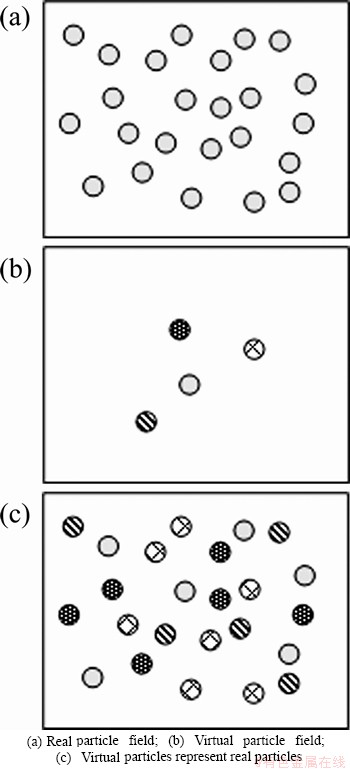
Figure 1 Schematic diagram of DSMC method:
2.2 Physical model for particle precision collision probability of abrasive flow
In the DSMC method, the probability of collision between particles determines whether particles will collide. There are two main types of models for dealing with particle collision probability. One type is the collision between particles in the two-phase flow field. A random collision model, such as the Kitron model [31] and the Lun model [32], is established on the basis of the Boltzmann equation [33]. Another type of model is the collision model between particles based on the Lagrange orbit equation, such as the Tanaka model [34] and the Oesterle model [35]. The Tanaka model is simpler than the other models, so the Tanaka model is selected for analysis.
In a grid with a mesh volume of V and a particle concentration of n��, the probability of collision between any two particles in the grid in a unit time is:
 (1)
(1)
where Dp is the particle diameter; Gij is the relative velocity of the two sampling particles; Pij is the probability of collision between two particles.
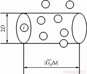
Figure 2 Physical model for particle collision probability
The particle velocity after collision can be obtained by the momentum equation [27].
 (2)
(2)
where  and
and  are the velocity of the two particles before the collision; vi and vj are the velocity of the two particles after the collision; n is the unit normal vector at the moment of collision from the centroid of particle i to the centroid of particle j; e is the collision recovery coefficient of particles (0
 .
.
2.3 Sampling algorithm for particle collision in abrasive flow precision machining
The important idea of DSMC method is to decouple particle motion from particle collision. In this paper, a modified Nanbu algorithm [36] is used to search for particle collision pairs.
The Nanbu algorithm [36] needs to calculate the collision probability of particles and each particle in the grid, which requires a large amount of calculation and a long calculation time. The modified Nnabu algorithm only needs to generate a random number once. The collision pair of particles can be selected, and whether the selected two particles collide with each other is determined.
The modified Nanbu algorithm divides the unit length into N+1 spaces, and tracks the probability of collision between particle i and particle 1, 2, ��, j, ��, N, and the length of each interval is Pi1, Pi2, ��, Pij, ��, PiN, and the general term of the interval is . Randomly extract a random number R uniformly distributed over the interval [0, 1], in which there are N particles in the grid, and then select particle j as the candidate particle. The value of j is given by:
 (3)
(3)
Calculate the particle collision probability Pij if the following formula is satisfied.
 (4)
(4)
Then, the particle i collides with particle j. The schematic diagram of the modified Nanbu algorithm is shown in the Figure 3.
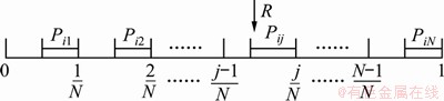
Figure 3 Schematic diagram of modified Nanbu algorithm
3 Numerical study of abrasive flow lapping elbow
3.1 Establishment of three-dimensional model of elbow
Since the 90�� elbow has a great demand in the military and civilian fields, the 90�� elbow was selected as the research object. The inner diameter of the elbow is 2 mm, the radius of curvature is 3 mm, and the lengths of both sides are 30 mm. In order to more accurately analyze the flow state distribution of the abrasive flow in different regions during the abrasive flow precision machining, the 3D model and area division of 90�� elbow are shown in Figure 4.
Since solid-liquid two-phase abrasive flow belongs to the category of multiphase flow, the calculation of turbulent multiphase flow needs to be solved. The multiphase flow model uses a dense discrete phase model combining a discrete phase model and a hybrid model, and the turbulence model uses a standard k-�� model. Among them, the empirical constants C��1=1.44, C��2=1.92, C��=1.3, and ��k=1.0. The DSMC method was used to simulate the collision of abrasive particles. Combining the DSMC method with the finite element simulation, the numerical solution of the precision machining process of solid-liquid two-phase abrasive flow was solved. According to the Reynolds equation, when the minimum speed is 25 m/s, the Reynolds number is greater than 4000. It can be confirmed that the liquid phase fluid has fully developed into turbulent flow. The boundary conditions of the velocity inlet and the free outlet can be adopted, and the wall condition was selected to be non-slip. Since the DSMC method requires instability analysis of the particles, and the time step should be small enough to ensure accurate sampling of the particle collisions, the particle time step was chosen to be 1��10-6s, the time step of the fluid is 1��10-4 s, and the calculation time is 1 s.
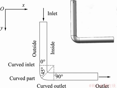
Figure 4 3D model and area division of 90�� elbow
3.2 Effect of inlet speed on precision machining quality of abrasive flow
In the abrasive flow precision machining process, the inlet speed affects the motion state of the fluid and directly affects the precision machining quality of the abrasive flow. The inlet velocity was 25, 30, 35, 40 m/s, the particle size was 48 ��m, the particle volume fraction was 4%, and the temperature was 300 K.
With the upper end of the elbow as the inlet and the right as the outlet, the abrasive flow precision machining process was numerically simulated, and the 90�� elbow dynamic pressure cloud diagram of the abrasive flow precision machining at different inlet speeds is shown in Figure 5.
It can be seen from Figure 5 that the precision machining of the 90�� elbow was performed at different inlet speeds, and the movement trend of the abrasive flow is about the same. The greater the inlet speed is, the more intense the movement is and the more the dynamic pressure increases. Dynamic pressure is converted from kinetic energy. Kinetic energy is related to the Preston material removal equation. Dynamic pressure characterizes the energy of the fluid. This energy causes particles to collide with the wall. Therefore, dynamic pressure can explain material removal [37]. Through analysis, it can be found that the abrasive flow at the inlet is smooth. The probability of collision between particles and between the particles and the wall is small, and the particle motion is not very violent, and the surface processing uniformity is good. The precision machining quality of the abrasive flow in the elbow is uneven. The dynamic pressure on the upper surface is greater than that on the lower surface, which is mainly due to the change in the shape of the flow channel that causes the curvature of the inner surface to change, the probability of collision between particles, and between particles and the wall surface to increase [38]. Originally, the particles moving with the carrier collided with each other under the change of the flow channel structure, and the collided particles hit the inner wall surface of the elbow and cause the dynamic pressure on the inner side of the elbow to increase; When the outer wall surface is in contact with the fluid, the speed gradually decreases, resulting in a decrease in the outer dynamic pressure. Therefore, the dynamic pressure on the outer wall surface of the curved portion is significantly smaller than that on the inner wall surface. However, since the abrasive flow is subjected to centrifugal force in the curved portion, its motion tends to gradually expand toward the outer wall surface, so the dynamic pressure on the outer wall surface gradually increases from the inlet of the curved portion to the outlet of the curved portion [39]. The abrasive flow is at the outlet, and the dynamic pressure of the abrasive flow is more disordered than that of the inlet portion. The particles colliding with the outer wall surface and the rebounding inner surface of the particles cause the dynamic pressure to gradually increase.
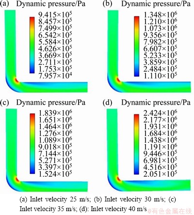
Figure 5 Dynamic pressure nephogram of abrasive flow precision machining 90�� elbow at different inlet speeds:
According to the analysis, for the precision machining of elbow parts, the variation of the inlet speed will affect the uniformity of the abrasive flow precision machining. Increasing the inlet speed will make the abrasive flow more intense in the internal flow channel of the pipe. There is a greater chance of collisions between particles and between the particles and the wall surface. The DSMC method can well simulate the collisions of particles, and the collision of the particles in the abrasive flow with the surface to be processed is more and more frequent, the times of micro-cutting increases, the material is excessively removed, and the processing effect will be less. In the actual abrasive flow precision processing, the inlet speed can be appropriately adjusted as needed.
In order to further analyze the dynamic pressure trend at different angles of the curved portion, the data were sampled from the outer wall to the inner wall surface at 0��, 45�� and 90��, respectively, and a three-dimensional graph of the dynamic pressure change trend at different angles of the bending portion at different inlet speeds is shown in Figure 6. In the 0�� section, the dynamic pressure in the central region is stronger than that in the inner and outer side walls. There is substantially no dynamic pressure difference between the inner and outer side walls. In the 45�� section, there is a clear dynamic pressure difference between the inner and outer side walls. The dynamic pressure on the outer side wall is lower than that on the inner side wall, and the dynamic pressure on the inner side wall reaches a maximum value. At the 90�� section, that is, at the exit of the curved portion, the dynamic pressure on the inner wall is smaller than that on the outer wall, and the dynamic pressure tends to increase first and then decrease from the outer side wall toward the inner side wall. As the inlet speed increases, the dynamic pressure at different bending angles gradually increases, but the movement trend is basically the same.
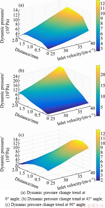
Figure 6 Trend of dynamic pressure at different angles of curved portion:
3.3 Effect of abrasive volume fraction on precision machining effect of abrasive flow
According to the Lagrangian calculation method, the volume fraction of the abrasive particles should not exceed 10%-15%. According to the author��s research summary, the volume fractions of the abrasive particles selected were as 4%, 6%, 8%, and 10%, respectively, and the inlet velocity was kept at 30 m/s, the particle size was 48 ��m, and the temperature was 300 K.
The numerical simulation of the precision machining of the 90�� elbow with the abrasive flow was carried out, and the turbulent flow energy cloud of the precision machining of the 90�� elbow with the abrasive flow under different abrasive flow conditions is shown in Figure 7.
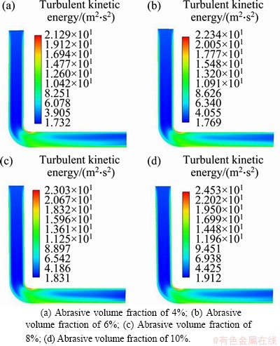
Figure 7 Turbulent flow energy nephogram of a 90�� elbow machined by abrasive flow at different mass flow rates:
Turbulence is an important feature of abrasive flow machining. Turbulence energy reflects the internal energy of the abrasive flow, indicating the intensity of particle motion, and directly affects the machining effect [13, 40]. It can be seen from the turbulent energy nephogram under different abrasive volume fractions in Figure 7 that the maximum turbulent energy appears on the inner wall of the bend of the elbow. Under different abrasive volume fractions, the trend of turbulent flow energy is basically the same. During the entire process of abrasive flow precision machining, the turbulent flow energy near the inner and outer walls is greater than that in the middle region. The larger the volume fraction of the abrasive particles, the greater the turbulent flow energy, the stronger the flow field disturbance, the more turbulent the motion of abrasive particles, the more times the abrasive flow particles collide with the wall, the more abrasive particles participating in the cutting surface, the more the times of cutting, and the greater the amount of material removal on the wall [41]. Defects such as surface protrusions and burrs are effectively removed. Therefore, increasing the volume fraction of the abrasive particles can effectively improve the precision processing quality of the abrasive flow. However, excessive turbulent flow energy may cause excessive material removal and damage the surface, reducing the processing quality. When the abrasive flow through the curved portion, the collision between particles bounces back to the inner surface, and the turbulence of the abrasive particles is further enhanced, resulting in an increase in turbulent flow energy, and the pressure on the inside also increases [41]. If the volume fraction of the abrasive particles is too large, when the abrasive particle flow precisely processes the small hole channel, the small holes may be blocked by the abrasive particles, thereby affecting the flow of the abrasive particles in the flow channel and failing to achieve the purpose of precision machining the inner surface. Therefore, appropriately increasing the volume fraction of the abrasive particles is conducive to increasing the fluidity of the abrasive flow in the flow channel, thereby effectively increasing the amount of material removal on the surface and improving the efficiency of the precision machining. In order to better analyze the trend of turbulent flow energy in the curved portion under different abrasive volume fractions, the data of 0, 45�� and 90�� of the curved portion were sampled, and the turbulent flow energy distribution data of the curved portion under different abrasive volume fractions are shown in Table 1.
Table 1 Distribution data of turbulent energy in bend under different abrasive volume fractions
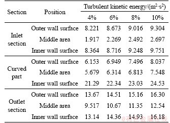
From the analysis of the flow energy distribution data of the curved portion in Table 1, it can be seen that: (1) At the same abrasive volume fraction, the turbulence kinetic energy at the two side walls is greater than that at the middle region, and the turbulence kinetic energy of the outlet is greater than that at the inlet, so the processing quality of the abrasive flow at the outlet is better than that at the inlet. When the turbulent flow energy is within a certain range, the turbulence kinetic energy at the inner wall surface of the curved part is the greatest, the time of cutting is large, and the machining quality of the abrasive flow is the best. (2) At different abrasive particle volume fractions, as the abrasive particle volume fraction increases, the turbulent flow energy of each curved part increases, and the times of cutting also increases. Therefore, appropriately increasing the volume fraction of the abrasive particles can improve the turbulent flow energy and the times of cutting in the abrasive flow precision machining, thereby improving the precision machining quality of the abrasive flow. However, excessive turbulent flow energy and the times of cutting may lead to excessive material removal and reduce machining quality.
3.4 Effect of abrasive particle size on precision machining of abrasive flow
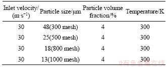
During abrasive flow precision machining, material removal on the surface of the elbow is mainly accomplished by the continuous impact of abrasive particles on the surface of the elbow. Different abrasive particle sizes have different impact effects on the surface of the elbow. The effects of different abrasive particle sizes on abrasive flow precision machining were analyzed. Numerical analysis of abrasive particle flow machining was performed by selecting abrasive particles with particle sizes of 300 mesh (48 ��m), 500 mesh (25 ��m), 800 mesh (18 ��m) and 1000 mesh (13 ��m). The specific parameter settings are shown in Table 2.
Table 2 Parameter settings for different abrasive particle sizes
At the same inlet and outlet, according to the parameter settings of Table 2, the numerical simulation of the precision machining of a 90�� elbow by abrasive flow was carried out, and the dynamic pressure cloud diagram is shown in Figure 8.
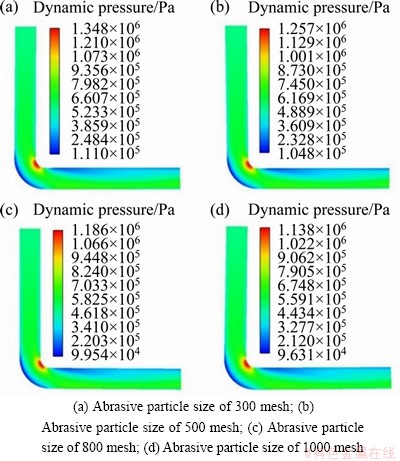
Figure 8 Dynamic pressure nephogram of 90�� elbow processed by abrasive flow under different abrasive particle sizes:
It can be seen from the dynamic pressure cloud diagram in Figure 8 that at different abrasive particle sizes, the maximum dynamic pressure appears on the inner side wall surface of the curved portion, and the dynamic pressure distribution trend is approximately the same. As the abrasive particle size increases, the impact between the abrasive particles and the wall is strengthened, and the dynamic pressure also increases [37]. The greater the dynamic pressure of the abrasive flow, the better the precision machining effect on the elbow wall. The smaller the abrasive particle size, the better the driving force of the fluid on the abrasive particles. Through the randomness of the fluid motion, the wall surface is randomly micro-cut, so that surface finishing can be achieved. The larger the abrasive particles, the greater the collision effect on the wall surface. The radial force of the abrasive particles gradually increases, and the cutting force gradually increases, and the depth of the particles cut into the surface increases, which can increase the amount of material removed on the machined surface [42]. Literature survey found that large-size abrasive particles can remove more surface material, but the surface roughness is still large; however, although the material removal rate of small-size abrasive particles is reduced, a better surface finish can be obtained [43, 44]. Therefore, large abrasive particles can be used for rough machining to remove large protrusions and burrs, and then replace the small abrasive particles for polishing. Regarding the curved portion, as the number of the particles increases, the mesh of the particles increases. The number of collisions between particles and between the particles and the wall surface increases, and more particles bounce back to the inside of the curved portion, resulting in an increase in dynamic pressure. Therefore, the micro-cutting effect of the particles on the wall is stronger. In order to better analyze the variation trend of the dynamic pressure of the bend at different abrasive particle sizes, the data of the 0��, 45�� and 90�� sections of the curved portion were sampled to obtain the dynamic pressure distribution data, as shown in Table 3.
Table 3 Dynamic pressure distribution data in different regions of bend at different abrasive particle sizes
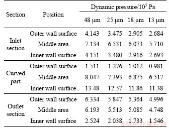
From the analysis of the dynamic pressure distribution data in Table 3, it can be seen that: (1) At the same particle size, the dynamic pressure distribution at the inlet is relatively uniform. The dynamic pressure at the inner side wall surface of the curved portion is higher than that at the outer side wall surface, and the dynamic pressure at the inner side wall surface of the outlet is lower than that at the outer side wall surface. Therefore, the abrasive flow precision machining elbow has better machining quality on the inner side wall surface of the bend and the outer side wall surface of the outlet. (2) At different abrasive particle sizes, as the particle size increases, the dynamic pressure also increases, and the surface machining effect is stronger. The larger the abrasive particle size, the greater the impact on the wall surface, the greater the depth of the particles cut into the workpiece, and the greater the amount of material removed from the wall surface, resulting in excessive removal of the surface material and damage to the internal matrix. The size of the abrasive particles should be selected according to the actual processing requirements to achieve the best surface processing quality.
4 Experimental study on precision machining of elbow by abrasive flow
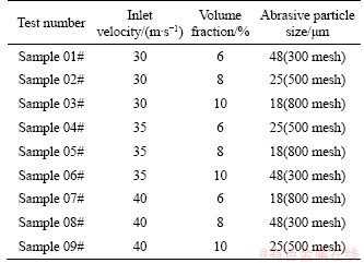
According to the numerical analysis results of the abrasive flow processing, the inlet speed, the abrasive volume fraction and the abrasive particle size were selected as the processing parameters of the abrasive flow. The material of the parts to be processed was 304 stainless steel, which has good processing performance and high toughness, and is widely used. Experimental studies were performed using three-level three-factor orthogonal tests. The selected inlet speeds were 30, 35 and 40 m/s. The abrasive particle volume fractions were 6%, 8% and 10%. The abrasive particle sizes were 300 mesh, 500 mesh and 800 mesh. Precision machining by abrasive flow was carried out. The 90�� elbow was analyzed by orthogonal test, and the design parameters of the orthogonal tests are listed in Table 4.
Table 4 Design parameters of orthogonal processing of 90�� elbow for precision machining by abrasive flow
4.1 Orthogonal test analysis of 90�� elbow for precision machining by abrasive flow
According to the orthogonal test design parameters shown in Table 6, the orthogonal test of the abrasive flow precision machining was performed on a 90�� elbow. After the abrasive flow precision machining is completed, the inner surface quality of the 90�� elbow needs to be checked. The main detection indicators are the inner surface roughness and surface topography of the elbow. Destructive testing of the elbow is required. The elbow after abrasive flow precision machining was cut with a wire-cutting machine, and a cross section view of the 90�� bend is shown in Figure 9.

Figure 9 Physical diagram of 90�� elbow after cutting
4.2 Detection of precision machining effect of abrasive flow on pipe fittings
The cut tube was observed by an electron microscopy, and the inner surface changes of the 90�� elbow before and after abrasive flow precision machining were observed. It can be seen from Figure 10 that the elbow has scratches, irregularities and poor surface quality on the inner surface before abrasive flow precision machining. After abrasive flow precision machining, the inner surface of the elbow becomes more and more smooth and the surface has slight scratches; the surface quality is greatly improved. Through a comparative analysis of the surface effects of the elbow before and after the abrasive flow precision machining, it can be seen that the quality of the inner surface of the elbow after the abrasive flow precision machining is significantly improved.
Although the precision machining effect diagram of the inner surface obtained by the electron microscope can be used to effectively analyze the surface effect before and after abrasive flow machining, the abrasive flow precision machining cannot be used to accurately detect the quality of the elbows, and the inner surface roughness of the elbow needs to be tested.
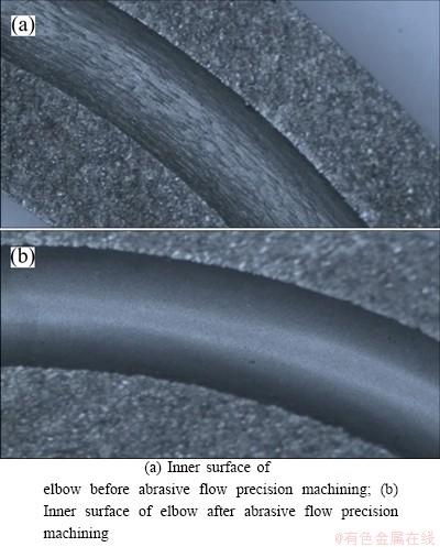
Figure 10 Effect of elbow inner surface before and after abrasive flow precision machining:
The inner surface roughness of the elbow before and after the abrasive flow processing was detected by a grating surface roughness meter, and the three-dimensional inspection diagram of the surface roughness of the elbow before and after the abrasive flow precision machining is shown in Figure 11.
It can be seen from Figures 11 and 12 that the inner surface roughness of the elbow without abrasive particle precision machining is uneven in the axial direction, and the surface of the workpiece is wavy, indicating that the inner surface of the elbow is uneven. The inner surface roughness of the elbow after being precisely processed by the abrasive particle flow is uniformly distributed in the axial direction, indicating that the inner surface of the elbow after the precision machining by the abrasive particle flow is relatively smooth. The abrasive flow precision machining can reduce the roughness of the inner surface of the elbow, thereby making the inner surface of the elbow smoother. In order to more accurately detect the surface roughness of the elbow, contact detection was performed on the inner surface of the elbow, thereby obtaining the inner surface roughness value of the elbow more accurately. The surface roughness values of the original sample and 9 samples taken from the processed elbows were obtained, and the specific values are listed in Table 5.
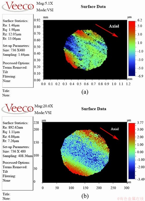
Figure 11 Three-dimensional inspection of surface roughness of elbow before (a) and after (b) abrasive flow precision machining
Table 5 Roughness measurements of original sample and samples from processed elbows
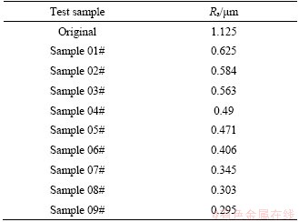
It can be seen from Table 5 that the surface roughness Ra of the elbow of the original sample is 1.125 ��m, and the maximum and minimum surface roughness measurements of the elbow after the abrasive flow precision processing are 0.625 ��m and 0.295 ��m, respectively, and the processing improves the surface roughness. This proves the effectiveness of the abrasive flow on precision machining of 90�� elbow. By selecting sample #03, sample #06 and sample #09 for analysis, it was found that as the inlet speed increases, the speed of particles and fluid increases, and the collision between particles and collision between particles and wall surface become more intense, and the surface roughness always decreases whether the particle size increases or decreases, and the effect of speed is greater than that of particle size.
4.3 Orthogonal test analysis of abrasive flow precision machining
Based on the measured values of the surface roughness of the nine samples, an analysis of the orthogonal test results is shown in Table 6. In Table 6, mean value 1, mean value 2 and mean value 3 represent the average values of the surface roughness measured under the test conditions of factor level 1, level 2 and level 3, respectively.
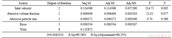
According to the orthogonal test results shown in Table 6, variance analysis was performed, as shown in Table 7.
In Table 7, Seq SS is the continuous sum of squares, Adj SS is the corrected sum of squares, Adj MS is the corrected mean square, F is the significance test value, S is the deviation sum of squares, P is the significance probability, and R-Sq is the goodness of fit
4.3.1 Factor significance test
It can be seen from the extreme values in Table 6 that the order of the primary to secondary influence of the three precision processing parameters on the surface quality by abrasive flow are inlet velocity>abrasive particle fraction> abrasive particle size. It can be determined that the inlet speed has the greatest influence on the precision machining by abrasive flow, and the abrasive particle size has the least influence on the precision machining by abrasive flow. The significance of the three processing parameters was tested according to the magnitude of the significance test value F in Table 7. The significance test value F of the inlet speed is 214.71, which is much greater than the F value of 12.01 corresponding to the abrasive volume fraction. Therefore, the influence of the inlet speed on the surface roughness of the precision machined elbow is significant compared to that of the abrasive volume fraction. The significance test value F of the abrasive particle fraction is 12.01, which is greater than the F value of 0.70 corresponding to the abrasive particle size. Therefore, the volume fraction of the abrasive particles has a significant effect on the surface roughness of the precision machined elbow compared to that of the abrasive particle size. The significance test value F of the abrasive particle size is 0.70, which is less than the F value when the significance level is 0.25. Therefore, the influence of the abrasive particle size on the surface roughness of the abrasive flow precision-machined elbow is not significant.
Table 6 Analysis of orthogonal test results

Table 7 Variance analysis of orthogonal test
4.3.2 Analysis of optimum process parameters for precision machining
The graphs for main effects of the test factors and the surface roughness shown in Figure 12 were obtained from the mean value 1, mean value 2 and mean value 3 under different factors in Table 6. By analyzing the main effects of the factors shown in Figure 12, it can be found that when the inlet speed is 40 m/s, the surface roughness of the elbow is minimal, and when the volume fraction of the abrasive particles is 10%, the surface roughness of the elbow is minimal. The minimum surface roughness of the elbow is corresponding to the abrasive particle size of 300 mesh.
It can be seen from Figure 12 that as the inlet speed increases, the surface roughness of the elbow gradually decreases. The change trend of the volume fraction is the same, i.e., the volume fraction increases, and the surface roughness of the elbow gradually decreases. The effect of the abrasive particle size on the abrasive flow precision machining is small. Under this experimental condition, when the abrasive particle size is 300 mesh, the machining effect of the abrasive particle flow is the best.
In short, under this test conditions, the optimal process parameters for precision machining of 90�� elbow by abrasive flow are inlet speed of 40 m/s, abrasive particle volume fraction of 10%, and abrasive particle diameter of 300 mesh.
4.4 Detection and analysis of surface morphology of 90�� elbow
In order to further investigate the improvement of the inner and outer surface quality of the curved part, the inner and outer surface of the elbow were tested for roughness. The inner and outer roughness values were 0.248 ��m and 0.298 ��m, respectively. The inside roughness is less than the outside roughness, and the inside surface is smoother, which validates the numerical analysis that the inside processing effect of the curved part is superior to the outside.
In order to better analyze the improvement of the surface morphology of the 90�� elbow before and after abrasive flow precision machining, the surface morphology of the elbow was examined using a scanning electron microscope. The surface morphology before the abrasive particle flow machining and the surface morphology at multiple locations after the abrasive particle flow machining of the elbow are shown in Figure 13.
It can be seen from Figure 13(a) that the surface topography before and after abrasive flow precision machining has changed greatly. Before the precision processing by the abrasive flow, there are many rugged burrs on the elbow surface. The distribution is irregular, and the surface quality is poor. It can be seen from Figures 13(b), (c) and (d) that the burr on the elbow surface after the abrasive flow precision machining has basically disappeared, and some stripe-like scratches and small pits appeared. In numerical analysis, surface processing is caused by particles hitting the wall. Combined with the test data to further analyze the action mechanism of the abrasive particles on the wall surface, after the particles hit the wall, the particles cut into the workpiece and the abrasive particles move forward with the carrier, resulting in micro plowing and micro cutting. GORANA et al [45] and KATO et al [46] explained the importance of this mechanism in the removal of abrasive flow materials. During the plowing process, the metal bulges on both sides of the abrasive flow direction to form a metal accumulation [44]. The metal on both sides was raised. Under the repeated ploughing action of the abrasive particles, the surface protrusions, burrs, etc. are removed to form some stripe-like scratches. LI et al [47] explained the stripe-like scratches. There are also some abrasive particles that impact the wall and rebound without cutting into the surface and small pits appearing. In general, the surface of the elbow is smoother and the surface quality is significantly improved.
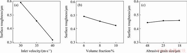
Figure 12 Test factors vs surface roughness
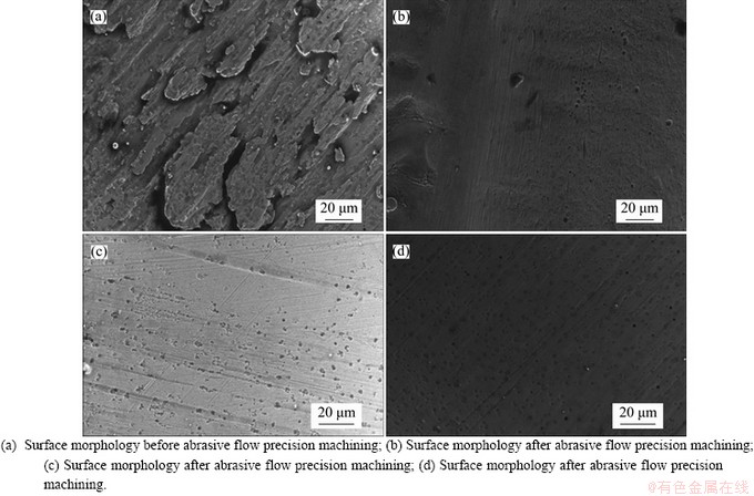
Figure 13 Surface morphology of 90�� elbow before and after abrasive flow precision machining:
5 Conclusions
The DSMC method and the finite element analysis were combined to analyze the random collision during the abrasive particle flow precision machining process, which reduced the amount of calculation and accurately predicted the surface behavior of the abrasive particle flow precision machining. The experiments verified the validity and reliability of the DSMC method for numerical analysis of abrasive particle flow precision machining. The following conclusions have been drawn:
(1) During the process of precision machining elbow by abrasive flow, the DSMC was used to analyze particle collision and material removal. The important process parameters were selected for numerical analysis. By numerically analyzing the effects of the inlet speed, abrasive particle volume fraction, and abrasive particle size on precision machining of 90�� elbows, it can be seen that as the inlet speed and volume fraction increase, the dynamic pressure and turbulent flow energy increase, and the degree of the fluid disturbance increases. Collisions between particles and between particles and walls are more severe, and frequent collisions between particles and between particles and walls are beneficial for removing burrs on the elbow wall and effectively improve the surface quality. As the particle size becomes smaller, the number of collisions between particles and between the particles and the wall surface increases, the particles frequently hit the wall surface, the dynamic pressure increases, and the micro-cutting effect on the wall surface is enhanced, which is conducive to the precise machining.
(2) Under the experimental conditions, the orthogonal test of precision machining of 90�� elbow by abrasive flow was studied, and three processing parameters, inlet speed, abrasive particle volume fraction and abrasive particle size were considered. The study found that the surface roughness of the 90�� elbow was precisely processed by the abrasive flow, and the surface roughness value was reduced from 1.125 ��m to 0.295 ��m. The optimal processing parameters for precise machining of a 90�� elbow by abrasive flow are inlet speed of 40 m/s, abrasive particle volume fraction of 10%, and abrasive particle size of 300 mesh. The primary and secondary influence order of processing parameters is: inlet speed > abrasive particle volume fraction > abrasive particle size. After abrasive flow precision machining, the burrs on the inner surface have basically disappeared, the scratches have been more uniform, and the inner surface quality of the elbow has been significantly improved.
Contributors
The overarching research goals were developed by LI Jun-ye, ZHU Zhi-bao, and WANG Bin-yu. ZHAO Wei-hong, and XU Cheng-yu carried out abrasive flow machining on the elbow workpiece. The initial draft of the manuscript was written by LI Jun-ye, ZHU Zhi-bao, and WANG Bin-yu. LI Jun-ye, ZHANG Xin-ming, and WANG Fei provided financial support. All authors replied to reviewers�� comments and revised the final version.
Conflict of interest
LI Jun-ye, ZHU Zhi-bao, WANG Bin-yu, ZHANG Xin-ming, WANG Fei, ZHAO Wei-hong, XU Cheng-yu declare that they have no conflict of interest.
References
[1] FU You-zhi, WANG Xuan-ping, GAO Hang, WEI Hai-bo, LI Shi-chong. Blade surface uniformity of blisk finished by abrasive flow machining [J]. International Journal of Advanced Manufacturing Technology, 2016, 84: 1725-1735. DOI: 10.1007/s00170-020-05589-z.
[2] BARAIYA R, BABBAR A, JAIN V, GUPTA D. In-situ simultaneous surface finishing using abrasive flow machining via novel fixture [J]. Journal of Manufacturing Processes, 2020, 50: 266-278. DOI: 10.1016/j.jmapro.2019. 12.051.
[3] SHAO Y, CHENG K. Integrated modelling and analysis of micro-cutting mechanics with the precision surface generation in abrasive flow machining [J]. International Journal of Advanced Manufacturing Technology, 2019, 105(11): 4571-4583. DOI: 10.1007/s00170-019-03595-4.
[4] ZHAO Jun, HUANG Jin-feng, WANG Rui, PENG Hao-ran, HANG Wei, JI Shi-ming. Investigation of the optimal parameters for the surface finish of K9 optical glass using a soft abrasive rotary flow polishing process [J]. Journal of Manufacturing Processes, 2020, 49: 26-34. DOI: 10.1016/j.jmapro.2019.11.011.
[5] GE Jiang-qin, JI Shi-ming, TAN Da-peng. A gas-liquid-solid three-phase abrasive flow processing method based on bubble collapsing [J]. International Journal of Advanced Manufacturing Technology, 2018, 95(1-4): 1069-1085. DOI: 10.1007/s00170-017-1250-9.
[6] CHEN Feng-jun, HAO Shan-mei, MIAO Xiang-liang, YIN Shao-hui, HUANG Shuai. Numerical and experimental study on low-pressure abrasive flow polishing of rectangular microgroove [J]. Powder Technology, 2018, 327: 215-222. DOI: 10.1016/j.powtec. 2017.12.062.
[7] CHERIAN J, ISSAC J M. Fatigue performance in abrasive flow machining [J]. Applied Mechanics & Materials, 2014, 592-594: 354-362. DOI: 10.4028/www.scientific.net/AMM. 592-594. 354.
[8] CHERIAN J, ISSAC J M. Effect of process parameters on wear performance in abrasive flow machining [J]. Applied Mechanics & Materials, 2015, 766-767: 661-667. DOI: 10.4028/www.scientific.net/AMM.766-767.661.
[9] SUSHIL M, VINOD M, HARMESH M. Multi-objective optimization of process parameters involved in micro-finishing of Al/SiC MMCs by abrasive flow machining process [J]. Proc IMechE Part L: J Materials: Design and Application, 2018, 232: 319-332. DOI: 10.1177/ 1464420715627292.
[10] LI Jun-ye, MENG Wen-qing, DONG Kun, ZHANG Xin-ming, ZHAO Wei-hong. Study of effect of impacting direction on abrasive nanometric cutting process with molecular dynamics [J]. Nanoscale Research Letters, 2018, 13(1): 11. DOI: 10.1186/s11671-017-2412-2.
[11] LI Jun-ye, ZHANG Heng-fu, WEI Li-li, ZHANG Xin-ming, XU Ying, XU Cheng-yu. Formation mechanism and quality control technology for abrasive flow precision polishing vortex: large eddy simulation [J]. International Journal of Advanced Manufacturing Technology, 2019, 105(5-8): 2135-2150. DOI: 10.1007/ s00170-019-04232-w.
[12] JI Shi-ming, TANG Bo, TAN Da-peng, GONG Bin, YUAN Qiao-ling, PAN Yan. Structured surface softness abrasive flow precision finish machining and its abrasive flow dynamic numerical analysis [J]. Journal of Mechanical Engineering, 2010, 46: 178-184. DOI: 10.3901/JME. 2010.15.178. (in Chinese)
[13] TAN Da-peng, JI Shi-ming, FU You-zhi. An improved soft abrasive flow finishing method based on fluid collision theory [J]. International Journal of Advanced Manufacturing Technology, 2016, 85(5-8): 1261-1274. DOI: 10.1007/ s00170-015-8044-8
[14] PAN Ye, JI Shi-ming, TAN Da-peng, CAO Hui-qiang. Cavitation-based soft abrasive flow processing method [J]. International Journal of Advanced Manufacturing Technology, 2020, 109: 2587-2602. DOI: 10.1007/s00170- 020-05836-3.
[15] SANKAR M R, JAIN V K, RAMKUMAR J, SAREEN S K, SINGH S. Medium rheological characterization and performance study during rotational abrasive flow finishing (R-AFF) of Al alloy and Al alloy/SiC MMCs [J]. The International Journal of Advanced Manufacturing Technology, 2018, 100(5-8): 1149-1163. DOI: 10.1007/s00170-018-2244-y.
[16] SINGH S, RAJ A S A, SANKAR M R, JAIN V K. Finishing force analysis and simulation of nanosurface roughness in abrasive flow finishing process using medium rheological properties [J]. Int J Adv Manuf Technol, 2016, 85: 2163-2178. DOI: 10.1007/s00170-015-8333-2.
[17] PETARE A C, MISHRA A, PALANI I A, JAIN N K. Study of laser texturing assisted abrasive flow finishing for enhancing surface quality and microgeometry of spur gears [J]. International Journal of Advanced Manufacturing Technology, 2019, 101: 785-799. DOI: 10.1007/s00170-018- 2944-3.
[18] MAIRE S, TALAY A D. On a Monte Carlo method for neutron transport criticality computations [J]. IMA Journal of Numerical Analysis, 2006, 26(4): 657-685. DOI: 10.1093/imanum/drl008.
[19] CHUNG M H, CHANG C H, CHANG K Y, WU Y S, GAO S F, SHEN Z P. A framework for train derailment risk analysis [J]. Journal of Central South University, 2019, 26: 1874-1885. DOI: 10.1007/s11771-019-4141-4.
[20] LI T, DIAS D. Tunnel face reliability analysis using active learning Kriging model-Case of a two-layer soils [J]. Journal of Central South University, 2019, 26(7): 1735-1746. DOI: 10.1007/s11771-019-4129-0.
[21] GAO H F, BAI G C, GAO Y, BAO T W. Reliability analysis for aeroengine turbine disc fatigue life with multiple random variables based on distributed collaborative response surface method [J]. Journal of Central South University, 2015, 22(12): 4693-4701. DOI: 10.1007/s11771-015-3020-x.
[22] PEREZ-CASTAN J A, GOMEZ COMENDADOR F, RODRIGUEZ-SANZ A, ARNALDO VALDES R M, ALONSO-ALARCON J F. Safe RPAS integration in non-segregated airspace [J]. Aircraft Engineering and Aerospace Technology, 2020, 92(6): 801-806. DOI: 10.1108/AEAT-11-2019-0224.
[23] ROMANO M, LOSACCO M, COLOMBO C, LIZIA P. Impact probability computation of near-Earth objects using Monte Carlo line sampling and subset simulation [J]. Celest Mech Dyn Astr, 2020, 132(8): 42. DOI: 10.1007/s10569-020- 09981-5.
[24] MOZAFFARI M S, ROOHI E. On the thermally-driven gas flow through divergent micro/nanochannels [J]. International Journal of Modern Physics C, 2017, 28(12): 1750143. DOI: 10.1142/ S0129183117501431.
[25] OZTURK S, KAHRAMAN M F. Modeling and optimization of machining parameters during grinding of flat glass using response surface methodology and probabilistic uncertainty analysis based on Monte Carlo simulation [J]. Measurement, 2019, 145: 274-291. DOI: 10.1016/j.measurement.2019. 05.098.
[26] KAHRAMAN M F, OZTURK S. Experimental study of newly structural design grinding wheel considering response surface optimization and Monte Carlo simulation [J]. Measurement, 2019, 147: 106825. DOI: 10.1016/ j.measurement.2019.07.053.
[27] DU Min, ZHAO Chang-sui, ZHOU Bin, GUO Hong-wei, HAO Ying-li. A modified DSMC method for simulating gas�Cparticle two-phase impinging streams [J]. Chemical Engineering Science, 2011, 66(20): 4922-4931. DOI: 10.1016/j.ces.2011.06.061.
[28] WAGNER W. A convergence proof of Bird��s direct simulation Monte Carlo method for the Boltzmann equation [J]. Journal of Statistical Physics, 1992, 66: 1011-1044. DOI: 10.1007/BF01055714.
[29] LI Jin, GENG Xiang-ren, CHEN Jian-qiang, JIANG Ding-wu. Novel hybrid hard sphere model for direct simulation Monte Carlo computations [J]. Journal of Thermophysics and Heat Transfer, 2017, 32: 1-5. DOI: 10.2514/1.T5162.
[30] TOMAS TISOVSKY, TOMAS VIT. Direct simulation Monte Carlo method for gas flows in micro-channels with bends with added curvature [J]. The European Physical Journal Conferences, 2017, 143: 02131. DOI: 10.1051/ epjconf/201714302131.
[31] KITRON A, ELPERIN T, TAMIR A. Monte Carlo simulation of gas-solids suspension flows in impinging streams reactors [J]. International Journal of Multiphase Flow, 1990, 16(1): 1-17. DOI: 10.1016/0301-9322(90) 90033-F.
[32] LUN C K K, SAVAGE S B. A simple kinetic theory for granular flow of rough, inelastic, spherical particles [J]. Journal of Applied Mechanics, 1987, 54(1): 47. DOI: 10.1115/1.3172993.
[33] BAKER L L, HADJICONSTANTINOU N G. Variance-reduced monte carlo solutions of the boltzmann equation for low-speed gas flows: A discontinuous galerkin formulation [J]. International Journal for Numerical Methods in Fluids, 2008, 58(4): 381-402. DOI: 10.1002/fld.1724.
[34] TSUJI Y, TANAKA T, YONEMURA S. Cluster patterns in circulating fluidized beds predicted by numerical simulation [J]. Powder Technology, 1998, 95(3): 254-264. DOI: 10.1016/S0032-5910(97)03349-4.
[35] OESTERLE B, PETITJEAN A. Simulation of particle-to- particle interactions in gas solid flows [J]. International Journal of Multiphase Flow, 1993, 19(1): 199-211. DOI: 10.1016/0301-9322(93)90033-Q.
[36] ILLNER R, NEUNZERT H. On simulation methods for the Boltzmann equation [J]. Transport Theory & Statistical Physics, 1987, 16(2, 3): 141-154. DOI: 10.1080/ 00411458708204655.
[37] ZHANG Li, WANG Jin-shun, TAN Da-peng, YUAN Zhi-min. Gas compensation-based abrasive flow processing method for complex titanium alloy surfaces [J]. International Journal of Advanced Manufacturing Technology, 2017, 92: 3385-3397. DOI: 10.1007/s00170-017-0400-4.
[38] ZHANG Li, YUAN Zhi-min, QI Zi-jian, CAI Dong-hai, CHENG Zhi-chao, QI Huan. CFD-based study of the abrasive flow characteristics within constrained flow passage in polishing of complex titanium alloy surfaces [J]. Powder Technology, 2018, 333: 209-218. DOI: 10.1016/j.powtec. 2018.04.046.
[39] LI Chen, XU Qing-duo, GE Jiang-qin, LI Zhi-an, GUO Li-ming. Study of soft abrasive flow field measurement based on particle image velocimetry [J]. Int J Adv Manuf Technol, 2020, 109: 2039-2047. DOI: 10.1007/s00170-020-05765-1.
[40] LI J, JI S, TAN D. Improved soft abrasive flow finishing method based on turbulent kinetic energy enhancing [J]. Chin J Mech Eng, 2017, 30: 301-309. DOI: 10.1007/ s10033-017-0071-y.
[41] JI Shi-ming, CAO Hui-qiang, ZHAO Jun, PAN Ye, JIANG En-yong. Soft abrasive flow polishing based on the cavitation effect [J]. Int J Adv Manuf Technol, 2019, 101: 1865-1878. DOI: 10.1007/s00170-018-2983-9.
[42] DING J F, ZHANG K H, XU Y C. Research on grain impacting load in abrasive flow machining [J]. Advanced Materials Research, 2013, 797: 405-410. DOI: 10.4028/ www.scientific.net/AMR.797.405.
[43] RHOADES L J. Abrasive flow machining [J]. Manufacturing Engineering, 2016: 75-78. DOI: 10.1007/978-3-319- 30198-3_18.
[44] JAIN R K, JAIN V K, DIXIT P M. Modeling of material removal and surface roughness in abrasive flow machining process [J]. International Journal of Machine Tools & Manufacture, 1999, 39(12): 1903-1923. DOI: 10.1016/ S0890-6955(99)00038-3.
[45] GORANA V K, JAIN V K, LAL G K. Forces prediction during material deformation in abrasive flow machining [J]. Wear, 2006, 260(1): 128-139. DOI: 10.1016/j.wear.2004.12. 038.
[46] KATO K, ADACHI K. Wear mechanisms[M]. Boca Raton: CRC Press, 2000. https://tohoku.pure.elsevier.com/en/ publications/wear-mechanisms.
[47] LI Jun-ye, WANG Li-xiong, ZHANG Heng-fu, HU Jing-lei, ZHANG Xin-ming, ZHAO Wei-hong. Mechanism Research and Discussion of the Quality of Precision Machining of a Fifth-order Variable-diameter Pipe Using Abrasive Flow [J]. Strojniski Vestnik-Journal of Mechanical Engineering, 2020, 66(6): 358-374. DOI: 10.5545/sv-jme.2020.6554.
(Edited by HE Yun-bin)
���ĵ���
ֱ�����ؿ����������ĥ�������ܼӹ������о�
ժҪ��������������ڱ��澫�ӹ����������Լ�ĥ�������ܼӹ�����п��������û���չ�����о���ͨ��������۷�������ֵ������ķ������з����о�����ֱ��ģ�����ؿ�����������Ԫ����������Ͻ�ʾĥ�������ܼӹ������п����������ײ���ڲ�ͬ��ĥ��������ٶȡ���������Լ�ĥ�������£��������ĥ�����Ķ�̬ѹǿ���������ܷ����ó��˿����Ա���ļӹ������Լ���ͬ�ӹ�������ĥ�������ܼӹ�������Ӱ����ɡ�������չʾ�˲�ͬ������ĥ�������ܼӹ�������Ӱ��˳���������Ź��ղ���������������ڱ���ĥ�������ܼӹ�ǰ����йر�����̬�Ľ�������Ҿ���ĥ�������ܼӹ������ֲڶ�Raֵ��1.125 ��m���͵���0.295 ��m��ֱ��ģ�����ؿ�������Ӧ��Ϊĥ���������ķ�չ�ṩ�ο���
�ؼ��ʣ�ĥ�������ܼӹ���ֱ��ģ�����ؿ�������ĥ����ײ���ӹ�����
Foundation item: Projects(51206011, U1937201) supported by the National Natural Science Foundation of China; Project (20200301040RQ) supported by the Science and Technology Development Program of Jilin Province, China; Project(JJKH20190541KJ) supported by the Education Department of Jilin Province, China; Project(18DY017) supported by Changchun Science and Technology Program of Changchun City, China
Received date: 2020-06-08; Accepted date: 2020-09-13
Corresponding author: ZHANG Xin-ming, PhD, Professor; Tel: +86-13644302228; E-mail: fstving@163.com; ORCID: https:// orcid.org/0000-0003-2796-1103
Abstract: The investigation was carried out on the technical problems of finishing the inner surface of elbow parts and the action mechanism of particles in elbow precision machining by abrasive flow. This work was analyzed and researched by combining theory, numerical and experimental methods. The direct simulation Monte Carlo (DSMC) method and the finite element analysis method were combined to reveal the random collision of particles during the precision machining of abrasive flow. Under different inlet velocity, volume fraction and abrasive particle size, the dynamic pressure and turbulence flow energy of abrasive flow in elbow were analyzed, and the machining mechanism of particles on the wall and the influence of different machining parameters on the precision machining quality of abrasive flow were obtained. The test results show the order of the influence of different parameters on the quality of abrasive flow precision machining and establish the optimal process parameters. The results of the surface morphology before and after the precision machining of the inner surface of the elbow are discussed, and the surface roughness Ra value is reduced from 1.125 ��m to 0.295 ��m after the precision machining of the abrasive flow. The application of DSMC method provides special insights for the development of abrasive flow technology.
