
DOI: 10.11817/j.issn.1672-7207.2016.11.009
����������ݼӹ�б�������γ������������
�����ƣ����ڵ�
(������ҵ��ѧ ����ѧԺ������ ������710072)
ժ Ҫ��
�ӹ�Ч�ʣ������ͳ��ָ��������������������ݼӹ�˫���γ�б������Ʒ��������ݿռ�����ԭ������3���ɶ��������ģ�ͣ���ƹ������μ�������������ת�����밲װ���ľ࣬���Ƶ��������γ��棻��Σ����LTCA�����Գ��ش������(LTE)��ֵ��СΪ�Ż�Ŀ�꣬��������ӹ�������������LTE��ֵ����ָ��غ϶ȹ�ϵ���о������������Ƽӹ������ɼ�С��װ��������ԣ������Ե�Ӵ������ָ�LTE��ֵ����44%����ˣ������ڽ��������������������г�������ʱ�������Ӻ����������˶���ʹ�ù��й����У������س�������ε������仯����������ͳ�ӹ�(�ı����ľ�)�����ij���Ť����
�ؼ��ʣ�
�����������������Ӵ����������ؽӴ����������ش��������
��ͼ����ţ�TH133 ���ױ�־�룺A ���±�ţ�1672-7207(2016)11-3677-08
Design and analysis for topologically modified helical gear finished by gear-hobbing
JIANG Jinke, FANG Zongde
(School of Mechanical Engineering, Northwestern Polytechnical University, Xi��an 710072, China)
Abstract: A design and an analysis of topologically modified helical gears were proposed to improve the machining efficiency and reduce the noise and vibration. Firstly, the topologically modified pinion tooth surfaces finished by hobbing was established according to the meshing theory of three independent motion parameters of the tight rational meshing between work-gear and hobbing cutter and the traverse motion of work-gear along the axis of the work gear and tangential feed along the axis of the hobber. Besides, the modified teeth were determined by the profile gear-hob, the center distance between work-gear and hobbing cutter, the hob tangential feed and additional rotation angle of work gear. Secondly, the parameters were individually determined based on TCA and LTCA by optimizing the aim of minimum the amplitude of loaded transmission error of drive gears. Finally, a numerical simulation of example was performed. The characteristics of amplitude of LTE curves were investigated by analyzing the contact ratio with increasing loads on modified gears. The results show that the optimal modified tooth surfaces can reduce sensitivity caused by errors of axes alignment and prevent the gear��s meshing teeth from colliding with each other at the boundary, and make lower amplitude of LTEs reduce by 44%, which contributes to a lower vibration and noise. Besides, an accurate tangential feed of the hob with longitudinal correction can attain an anti-twist helical gear tooth flank with longitudinal tooth crowning, because continuous changes in profile along longitudinal of hobber contribute to reducing distortion of profile due to variable center distance hobbing without compensation of profile.
Key words: gear-hobbing; topological modification; TCA; LTCA; loaded transmission error
���ݼӹ���һ�ָ�Ч�����õ�Բ�����ּӷ������㷺Ӧ����ֱ�ݡ�б�ݡ����ֳ���ӹ��������ִ����ع��ݼ�����չ�����ݼӹ����ȡ�Ч��������ߣ�����ߵ����ع��ݻ��ӹ������Ѵ�4����ͨ�����ƻ����˶������ι���������Լӹ�����ӱ���������γ��湤���������ƽ���ὥ���߳��洫��������������������������У����ع�����������⣬������1���ع����������߷������������˶���Ϊ3���ɶȼӹ������ŵ��ǹ�����ȫ���ڵ����е��ݶ�����������ʹ�����ݵĸ��ɾ���, �������ö���ߣ�������Ⱥ;��ȸߡ���������ԭ������1�Խ����ὥ���߳��ִ�����CHIU��[1]�о�������ʹ�������������������£����ݳ��������Ҫ��Դ�ڹ�������������ӹ����ľ���NAGATA[2]������ͨ��6��CNC���ݻ�ģ�ͣ��о��˶����ɶȹ��ݼӹ��������Ƶ��˻��������˶���ϵ��Ϊ����߹��ݼӹ�Ч�ʣ�BOUZAKIS��[3-4]ͨ����������������˹���ĥ��������ģ�ͣ�Ԥ���˹���ĥ������VEDMAR[5]������������������ⷽ��Ϊƽ�����ߣ�ͨ���������������õ��������ܵ���ò��Ԥ�㹤������ֲڶȡ�INNOCENTI[6]ͨ����������õ����ݰ�װ����(�ύ�������ľ�)�����ϲ�϶��ϵ��Ϊ��ʵ��0��϶���ϣ��õ���Ѱ�װ������XIA��[7]ͨ����������ʵ��������ݼӹ���Բ���֡�HSU��[8-10]������2���ɶȹ���ģ�ͣ�ͨ���ı�����ݺ����������������������ת�ǣ�ʵ�ֳ�����Ť������ӹ����������˳�����γݷ���(TCA)��RADZEVICH��[11-14]ͨ���Թ���������Ƽ��˶�ѧ������ȷ���˹��ݹ������������С���г̾��룬���ڷ���������������в��������϶��伸�β����������ӹ����������Ż�������˹����ӹ����澫�ȡ� Ϊ����߹����ӹ����ȣ�SHIH��[15]������CNC 5����������ǰ����߽�У��ģ�ͣ�ͨ����С���˷���û����˶������������о������ڼӹ�������Ĺ�������������������δ�漰�����������γ��漰�������������о����ִ����ؼ����ķ�չʹ��ͨ�����ƻ����˶������ι������Σ�ʵ�ֹ����������γ���ļӹ��ﵽ������Ч���ѳ�Ϊ���ܡ����ֳ��ش������(LTE)�ѱ�֤ʵ�Dz���������������Ҫ����[16-17]��WANG��[18]ͨ��Ԥ��4��UTE���Ӵ�·�������ݾֲ��ۺϷ��Ƶ��������ּӹ�������SIMON��[19-20]����һ�ֳ��ؽӴ�����(LTCA)ģ�ͣ�ͨ���Ż����������˶��������˶�ϵ����ʹLTE��ֵ������70%~80%������δ�����Ż�������ARTONI��[21]ͨ���Ż�˫����LTEs��ֵ������Ӧ����С���õ������ϳ����������������ˣ����ͨ����ƹ��ݼӹ������������γ���ӹ������ͳ��ָ�LTE��ֵ���ﵽ������Ч������Ҫ���塣�������߸��ݿռ�����ԭ������3���ɶ��������ģ�ͣ�ͨ����ƹ������μ�������������ת���ǡ����ľࡢ��������ٶȣ��Ƶ������������γ��棻���LTCA������LTE��ֵ��СΪ�Ż�Ŀ�꣬��ù����������μ��˶�������
1 ����չ�ɽ����߳���
��ͳ��������Ϊ�����߳��棬Ϊ�˼ӹ����γ��棬��Ҫ�Թ�������������Σ���ͼ1(a)��ͼ1(b)��ʾ������a1��a2Ϊ�����ij������β�����anΪ����ѹ���ǣ�mnΪ����ģ�������ݳ���չ�ɽ����߳���ԭ��(��ͼ1(c))��չ�ɹ���������ֳ����ʾΪ��
 (1)
(1)
 (2)
(2)
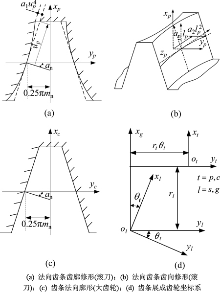
ͼ1 ����չ�ɹ���������ֳ���
Fig. 1 Coordinate systems of modified rack-cutter and generating helical gear
 (3)
(3)
ʽ�У�Rl��nl�ֱ�Ϊλʸ�ͷ�ʸ���±�lΪh��g���ֱ��ʾ����������֣�rtΪ�������λʸ���±�tΪp��c���ֱ��ʾչ�ɹ���������ַ���������ut��lt�ֱ�Ϊ����������rtΪ��Բ�뾶����tΪչ�ɽǡ�
2 ���������ѧģ��
���ݼӹ�������1������ὥ����Բ�����ִ����������������빤�����������γ�1���ύ�Ǧã��������ľ�ΪE0(��ͼ2(a)��ʾ)��Sh��S2�ֱ�Ϊ����������������ϵ��Sa��Sb��Sc��Sd�ֱ�Ϊ�ο�����ϵ�����ݹ�������Ҫ��3���˶����������������ת����ת��Ϊ��1�������ع������������λ��Ϊlz�������ع����������������λ��Ϊly��������������ת����ת��Ϊ��2����װ�����ú�E0��ʾΪ��
 (4)
(4)
 (5)
(5)
������ݹ����������ٶ�ͨ��Ϊ�����ٶȵ����Ժ�����
 (6)
(6)
�������ʱ�����ڹ�����������������������������Ҫ�и���ת�ǣ�����ת��Ϊ
 (7)
(7)
ʽ�У���1�ͦ�2�ֱ�Ϊ������С��(����)�����ǣ��������й�ϵ��ͬ��ȡ��������ȡ����Z1��Z2�ֱ�Ϊ������С�ֳ���(ͷ��)��a3Ϊ���������˶�ϵ����r1��r2�ֱ�Ϊ���������Ľ�Բ�뾶��
����ʽ(6)��(7)������ݿ��Լ�Ϊ2���ɶȹ��ݣ��ù�����lz���1Ϊ�������˶�����������֮��û�к�����ϵ�����ݿռ��������ԭ��������������λʸ������ϵSh�任����������ϵS2�У�ͬʱ��lz�ͦ�sȡij��ֵʱ����Ӧ�������Ϸ���ʽ����ˣ���������λʸ����ʸΪ��

 (8)
(8)
 (9)
(9)
 (10)
(10)
 (11)
(11)
ʽ�У�M1a ��Mab��Mbc��Mcd��MdhΪ�ӹ���������������任����L1a��Lab��Lbc��Lcd��LdhΪ����Ӧ3��3�Ӿ���
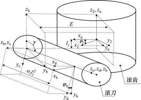
ͼ2 �����������ϵ
Fig. 2 Coordinate systems for hobbing a work gear
3 ������������������
ͨ�����ι������μ��ı乤��ת�Ǽ����ľ��ʵ�ֳ�������Σ���
 (12)
(12)
 (13)
(13)
�����滮��Ϊ9��15�����Աȹ�������������߳��棬����i��j������������ʾΪ

 (14)
(14)
4 �Ż�LTE��ֵ������ݼӹ�����
4.1 ����Ӵ�����
ͨ������չ�ɹ������漰���ֳ���(�������߳���)����ͨ�������������2���ɶ�������ݵõ�С�����γ��棬С���ֳ������Ϊup��lp����p����1��lz�������ֳ������Ϊug��lg�ͦ�g��ͼ3��ʾΪ���ָ���װ����ϵ�����У�S1��S2�ֱ�ΪС�֡������˶�����ϵ��Sh1��Sh2��SfΪ�ο�����ϵ��E����EΪ��װ���ľ༰������Ϊ�ύ�ǰ�װ�� ��
�� �ֱ�ΪС�֡�����ת�ǣ�TCA���̱���ʽΪ��
 (15)
(15)
 (16)
(16)
 (17)
(17)
ʽ�У�Mf1��Mf2��Lf1��Lf2�ֱ�Ϊ���涯����ϵ���̶�����ϵ��ת������
ʽ(17)�У�����Ϊup��lp����p����2��ls��ug��lg����g����������10����ȡΪ�������������Ϊ9������Ҫ9�����̿�ȷ��Ψһ�⡣ʽ(17)�ɷֽ�Ϊ5������ʽ������4�����Ϸ���ʽ����ʽ(3)Ϊ����չ�ɴ��֡������ݵ��������Ϸ���(����2��)��ʽ(10)~(11)Ϊ��������С�ֳ������Ϸ��̣���ȷ��Ψһ�⡣ͨ��TCA�õ�UTEΪ
 (18)
(18)
ʽ�У� ��
�� �ֱ�ΪС�֡����ֳ�ʼת�ǣ�ZgΪ���ֵij�����
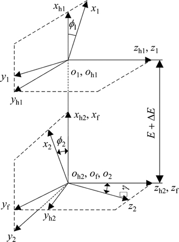
ͼ3 TCA��װ����ϵ
Fig. 3 Coordinate system applied for TCA
4.2 �Ż�ģ��
���ĵ�LTCA����[22]��һ����TCA�����ϣ�������Ԫ���뼸�μ��������������Ƕ�ݶԽӴ��������ָ������Ӵ�ת��Ϊ������������ɢ�Ӵ������ѧƽ�����⣬ͨ�������η����������Է�����õ����غ���ָ�˲ʱ�Ӵ�������ɢ����غɺ�һ���������ڷ�����Σ����÷������Zת��Ϊ�������ϵ�λ�ƣ���ת��(��λ��(��))��ʽ��ʾ����һ���������ڵ�LTEΪ
 (19)
(19)
ʽ�У�Rbg�ͦ�g�ֱ�Ϊ�������ֻ�Բ�뾶�������ǡ�
ͨ���Ż�һ���������ڵ�LTE��ֵ��Сȷ������ϵ��as, ds, ls��Ŀ�꺯����ʾΪ
 (20)
(20)
�Ż����̼�ͨ���ı�����������β����������˶����������Ż�����Ϊx=[a1, a2, a3, a4, a5, a6,a7], �ı�С�ֳ����������������ı���ָ��ĽӴ���϶������TCA��LTCA��һ�������Ե������̣��Ż��������Ż�Ŀ�꺯��֮��û��ֱ����ϵ����ʵ���в��ܽ������Ż�������Ŀ�꺯���Ľ�������ʽ���������Ż���ռ��ڴ��ڶ���ֲ����Ž⣬��ˣ���ͳ���Ż��㷨�ڴ˲������ã�����Ⱥ�㷨�Ҿ���ȫ�������ԣ����������ж���ֲ���ֵ�ķ������Ż����⣬�ṹ����˱���Ӧ�ø��Ż��㷨��⣬��������ͼ4��ʾ��
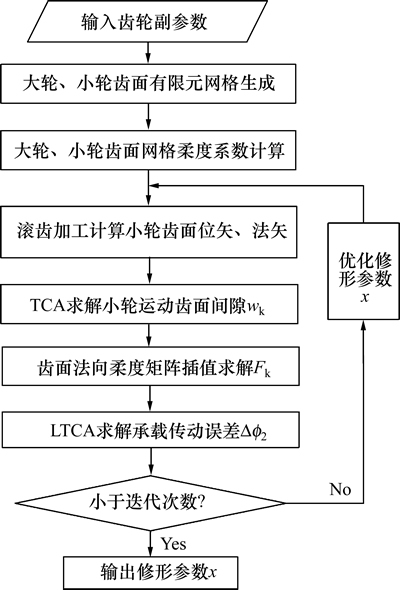
ͼ4 ���β����Ż�����ͼ
Fig. 4 Flowchart of modification parameters optimization
5 ���������
������[9]�й�����б���ָ�����Ϊ��(����1)������Ť��500 N��m����Ϊ�Ż�Ŀ�꣬����չ�ɹ����ij�����������4�����������Σ��������2�����������Ρ��������г�������ʱ����������Ť���̶��ܹ�����������ٶ�Ӱ�죬��ˣ����ĸ���������������ϵ����a2=-1��10-8����Ҫ�Ż������������β���a1��������������ٶȲ���a3���������ľ����a4�����ݹ�������ת�Dz���a5~a7����6�����Ż��������2��������γ���(ͼ5)���������£�1) �����ι������κ��Թ���������������(ͼ6(a))���Թ������г������κ������ٶȽ�Ӱ�����Ť���̶ȣ��������˶�ϵ��a7=3.2ʱ��������Ť������(ͼ6(b)~(d))����Ҫ˵�����ǣ�Ť���̶��������������������������йأ��ı����ľཫ���¹�������Ť��(ͼ6(e))��������������ת�ǵ��¹�������Ť��(ͼ6(f)~(h))���ɼ����������س�������������������һ��ʱ���������Ȼ���������ٶȼ��������ľ�仯�Թ�������Ť���̶�����ҪӰ�죻ͨ���Թ����س�����г������κ������������˶���ʹ�ù��й����в����س�������ε������仯���ֲ��˴�ͳ�ӹ�(�ı����ľ�)���ڹ��������ޱ仯��������Ť����2) ���γ����غɷֲ����ȣ��غ���Ҫ�ֲ��ڳ����в����ޱ�Ե�Ӵ����а�װ���ʱ���غ�����˲��ƶ�(ͼ7(a)~(d)��ͼ8(a)~(d))�����ν����˳��ָ��İ�װ��������ԣ�3) ������ʱ��1���������ڳ���˫�ݡ����ݽ������ϣ�˫�����������δ�����������������(��ͼ9(a))�������غ϶Ȳ��䣬��ˣ����غ����ӣ�˫�ݽ������������������������κ����غ������ֵ���˫�ݽ����������غ϶Ȳ�������(0~400 N��m)��˫�����ݽ����������غ϶Ȳ�������(400~700 N��m)������(��700 N��m) 3��״̬(ͼ9(b))����ˣ����ڳ��ش�������ֵ��������3���仯�����ǣ����ڳ����г������Σ����Ӵ����Ϸ����϶Ӱ���غ϶ȱ仯����3�α仯�ڳ��ش�����������ϲ��Ǻ�����(ͼ9(c))��
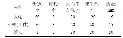
��1 ���ݻ�������
Table 1 Basic parameters for gear hobbing process
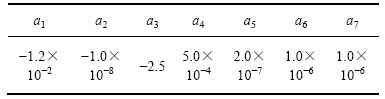
��2 �Ż������β���
Table 2 Optimal coefficient for modified pinion
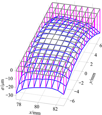
ͼ5 �Ż���������������
Fig. 5 Optimal ease-off topography for pinion
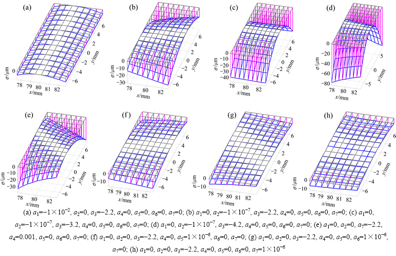
ͼ6 ��ͬ����ϵ���ķ���������
Fig. 6 Ease-off topography for pinion with different coefficients
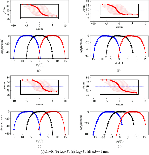
ͼ7 ���γ���TCA�������
Fig. 7 Simulation analysis of TCA for meshing of modified pinion and gear
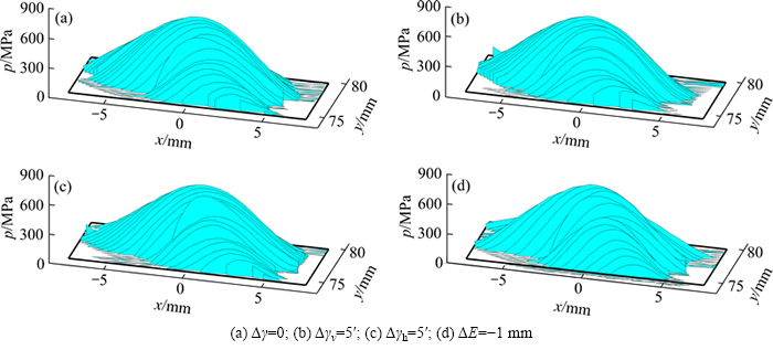
ͼ8 С�ֳ����غɷֲ�
Fig. 8 Loads distribution on pinion surface
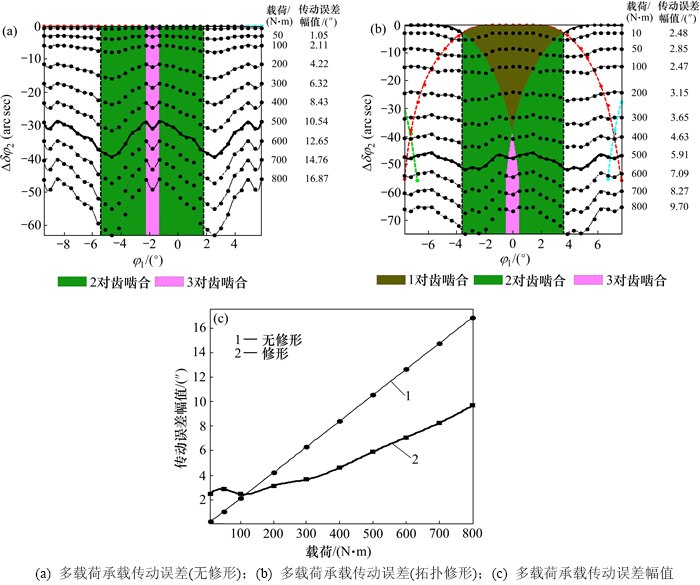
ͼ9 ���غ�LTE��ֵ�����εı仯
Fig. 9 Wave form and amplitude of LTE curves under multi-loads for gears
6 ����
1) ���ݿռ�����ԭ����������3���ɶ��������ģ�ͣ�����˹����������������β������˶����β���������˹����������γ��档
2) ���LTCA������LTE��ֵ��С����ù����������β������˶�������������������������γ��ֿɼ�С��װ��������ԣ������Ե�Ӵ������ͳ��ָ�LTE��ֵ����С����������
3) �������г�������ʱ����������������ٶȿɱ��������Ť����
4) �����γ��������غ϶Ȳ��䣬��ˣ����غ����ӣ�LTE��ֵ�������ӣ����κ����غ����ӣ������϶��ѹʵ�غ϶Ȳ������ӣ���ˣ�LTE��ֵ���ͣ��������϶��ȫѹʵ���غ϶Ȳ��ٱ仯�����غ����ӣ��������������
�ο����ף�
[1] CHIU H, UMEZAKIY Y, ARIURA Y. An improvement of the tooth profile accuracy of a hobbed gear by adjusting the hob eccentricity[J]. JSME International Journal: Ser. 3. Vibration, Control Engineering, Engineering for Industry, 1989, 32(1): 131-135.
[2] NAGATA S A General mathematical model for gears cut by GNC mobbing machines[J]. Journal of Mechanical Design, 1997, 119(1): 108-113.
[3] BOUZAKIS K D, ANTONIADIS A. Optimizing of tangential tool shift in gear hobbing[J]. CIRP Annals Manufacturing Technology, 1995, 44(1): 75-78.
[4] BOUZAKIS K D, KOMBOGIANNIS S, ANTONIADIS A, et al. Gear hobbing cutting process simulation and tool wear prediction models[J]. Journal of Manufacturing Science and Engineering, 2002, 124(1): 42-51.
[5] VEDMAR L. A parametric analysis of the gear surface roughness after hobbing[J]. Journal of Mechanical Design, 2010, 132(11): 111004-1-111004-8.
[6] INNOCENTI C. Optimal choice of the shaft angle for involute gear hobbing[J]. Journal of Mechanical Design, 2008, 130(4): 044502-1-044502-5.
[7] XIA L, LIU Y, LI D, et al. A linkage model and applications of hobbing non-circular helical gears with axial shift of hob[J]. Mechanism and Machine Theory, 2013, 70: 32-44.
[8] HSU R H, SU H H. Tooth contact analysis for helical gear pairs generated by a modified hob with variable tooth thickness[J]. Mechanism and Machine Theory, 2014, 71: 40-51.
[9] HSU R H, TSAY C B. Study on the anti-twist helical gear tooth flank with longitudinal tooth crowning[J]. Journal of Mechanical Design, 2014, 136(6): 061007-1-061007-10.
[10] HSU R H, FONG Z H. Novel variable-tooth-thickness hob for longitudinal crowning in the gear-hobbing process[J]. Mechanism and Machine Theory, 2011, 46(8): 1084-1096.
[11] RADZEVICH S P. About hob idle distance in gear hobbing operation[J]. Journal of Mechanical Design, 2002, 124(4): 772-786.
[12] RADZEVICH S P. A way to improve the accuracy of hobbed involute gears[J]. Journal of Mechanical Design, 2007, 129(10): 1076-1085.
[13] RADZEVICH S P. Investigation of the tooth geometry of a hob for machining of involute gears (in the tool-in-use reference system)[J]. Journal of Manufacturing Science and Engineering, 2007, 129(4): 750-759.
[14] RADZEVICH S P. A novel design of cylindrical hob for machining of precision involute gears[J]. Journal of Mechanical Design, 2007, 129(3): 334-345.
[15] SHIH Y P, CHEN S D. A Flank correction methodology for hob sharpening on the five-axis CNC hob sharpening machine[J]. Computer-Aided Design and Applications, 2012, 9(4): 585-598.
[16] CHENG Y, LIM T C. Dynamics of hypoid gear transmission with nonlinear time-varying mesh characteristics[J]. Journal of Mechanical Design, 2003, 125(2): 373-382.
[17] WANG J, LIM T C, LI M. Dynamics of a hypoid gear pair considering the effects of time-varying mesh parameters and backlash nonlinearity[J]. Journal of Sound and Vibration, 2007, 308(1): 302-329.
[18] WANG P Y, FONG Z H. Fourth-order kinematic synthesis for face-milling spiral bevel gears with modified radial motion (MRM) correction[J]. Journal of Mechanical Design, 2006, 128(2): 457-467.
[19] SIMON V V. Design and manufacture of spiral bevel gears with reduced transmission errors[J]. Journal of Mechanical Design, 2009, 131(4): 041007-1-041007-11.
[20] SIMON V V. Loaded tooth contact analysis and stresses in spiral bevel gears[C]//ASME 2009 International Design Engineering Technical Conferences and Computers and Information in Engineering Conference. American Society of Mechanical Engineers, 2009: 271-279.
[21] ARTONI A, KOLIVAND M, KAHRAMAN A. An ease-off based optimization of the loaded transmission error of hypoid gears[J]. Journal of Mechanical Design, 2010, 132(1): 011010.
[22] ZHANG Y, FANG Z. Analysis of transmission errors under load of helical gears with modified tooth surfaces[J]. J Mech Des, 1997, 119(3): 120-126.
(�༭ �°���)
�ո����ڣ�2016-01-11�������ڣ�2016-04-25
������Ŀ(Foundation item)��������Ȼ��ѧ����������Ŀ(51175423, 51375384) (Projects(51175423, 51375384) supported by the National Natural Science Foundation of China)
ͨ�����ߣ����ڵ£����ڣ���ʿ����ʦ�����³����������ۡ�������Ƽ���������ѧ���о���E-mail: fauto@ nwpu.edu.cn
ժҪ��Ϊ������γ��ּӹ�Ч�ʣ������ͳ��ָ��������������������ݼӹ�˫���γ�б������Ʒ��������ݿռ�����ԭ������3���ɶ��������ģ�ͣ���ƹ������μ�������������ת�����밲װ���ľ࣬���Ƶ��������γ��棻��Σ����LTCA�����Գ��ش������(LTE)��ֵ��СΪ�Ż�Ŀ�꣬��������ӹ�������������LTE��ֵ����ָ��غ϶ȹ�ϵ���о������������Ƽӹ������ɼ�С��װ��������ԣ������Ե�Ӵ������ָ�LTE��ֵ����44%����ˣ������ڽ��������������������г�������ʱ�������Ӻ����������˶���ʹ�ù��й����У������س�������ε������仯����������ͳ�ӹ�(�ı����ľ�)�����ij���Ť����
