
Trans. Nonferrous Met. Soc. China 23(2013) 1957-1965
Effects of welding parameters and tool geometry on properties of 3003-H18 aluminum alloy to mild steel friction stir weld
M. DEHGHANI, S. A. A. AKBARI MOUSAVI, A. AMADEH
School of Metallurgy and Materials Engineering, College of Engineering, University of Tehran, Tehran, P.O. Box 11155-4563, Iran
Received 2 July 2012; accepted 27 December 2012
Abstract:
Defect-free butt joints of 3003 Al alloy to mild steel plates with 3 mm thickness were performed using friction stir welding (FSW). A heat input model reported for similar FSW was simplified and used to investigate the effects of welding speed, rotation speed and tool shoulder diameter on the microstructure and properties of dissimilar welds. The comparison between microstructure, intermetallics and strength of welds shows the good conformity between the results and the calculated heat input factor (HIF) achieved from the model. The joint strength is controlled by Al/Fe interface at HIF of 0.2-0.4, by TMAZ at HIF of 0.4-0.8 and by intermetallics and/or defects at HIF>0.8.
Key words:
friction stir welding; dissimilar joining; microstructure; tensile strength; aluminum alloy; carbon steel; intermetallic compound;
1 Introduction
Nowadays, by employing severe environmental preservation laws as well as growing fuel prices, the transportation systems have inclined to the low- consumption vehicles. The reduction in consumption may be obtained through the lightening of vehicle by using aluminum or magnesium in various parts of the vehicle. However, using of aluminum in industries may result in some problems such as the process of joining aluminum to steel. Joining of aluminum to steel is generally difficult because of differences between their physical and chemical properties. Both alloys have incomparable melting points, thermal conductivity, coefficient of linear expansion and heat capacities, as reported by CARDARELLI [1]. Considering the phase diagram of Al-Fe system [2], the low solubility of iron in aluminum promotes the formation of brittle intermetallic compounds such as Fe2Al5, FeAl3, in the weld zone. As a result of such difficulties, especially the formation of thick intermetallic layers, creation of a strong joint between aluminum and steel sounds impossible or very difficult by using common fusion welding techniques. To join aluminum to steel, techniques such as diffusion bonding [3], friction welding [4], ultrasonic welding [5] and laser welding [6] could be used. Friction and explosive welding are limited to a few weld joint geometries. However, ultrasonic and laser welding are almost limited to joining of thin plates.
Friction stir welding which was invented and patented by THOMAS et al [7] is widely employed in industry for joining aluminum alloys. FSW is also applicable to the welding of dissimilar materials and some experiments have been published on joining aluminum to steel. UZUN et al [8] investigated the microstructure, hardness and fatigue properties of friction stir butt welded 4 mm thick aluminum 6013-T4 to X5CrNi18-10 stainless steel. They successfully obtained sound joints and characterized several distinct regions of dissimilar weld such as HAZ and TMAZ in both base metals; however, they did not investigate the effect of process parameters on the mechanical properties of joints. WATANABE et al [9] investigated the effect of tool rotation speed and pin position on the tensile strength of 2 mm thick 5083 aluminum alloy and mild steel sheets. TANAKA et al [10] analyzed the effect of rotation speed on temperature rise and joint strength of 7075-T65 aluminum alloy and mild steel at the condition of constant welding speed, and the effect of heat input on the formation of intermetallic compounds and resultant tensile strength was investigated. CHEN and Kovacevic [11] studied the feasibility of joining Al 6061 to AISI 1018 steel. They reported the effect of pin position on the temperature distribution and microstructure of weld zone at constant tool rotation and traverse speed. LEE et al [12] examined the type of intermetallic compounds produced in the reaction layer between friction stir welded 6056-T4 Al alloy and 304 austenitic stainless steel. Due to the nature of FSW process, with correct selection of welding parameters, no melting of base alloys is expected. Thus, the formation of intermetallic compounds decreases noticeably. Therefore, FSW can be considered a practical solution for industrial joining of aluminum alloy to steel.
In FSW the heat is generated by a combination of friction and plastic deformation. There are several investigations on modeling and calculation of heat input during FSW. FRIGAAD et al [13] and HEURTIER et al [14] proposed a numerical and semi-analytical three- dimensional heat flow model for FSW of aluminum alloys. They considered the heat generation from friction and neglected the deformational heat. The calculated results of the model were in good agreement with the experimental measurements performed on 6082-T6 and 7108-T79 [13] and 2025-T351 [14]. SCHMIDT et al [15] developed an analytical model for heat generation during FSW based on different contact conditions at tool/material interface. They considered both the plastic deformation and the friction between the tool shoulder and the tool pin using a weighting factor to adjust sticking and/or slipping condition during the process. The model was validated by the experimental work on 2024-T3 alloy [15].
In spite of different methodologies used to develop aforementioned models, the devised equations are almost similar in variables (i.e. applied pressure, rotation speed and tool diameter). It was reported that the heat generated from plastic deformation is about 5% [16] and the shoulder controls the heat generation during FSW [17]. Therefore, by neglecting the heat from the plastic deformation and the tool pin, the devised equations for heat generation reported in Ref. [15] will be similar to that in Ref. [13].
To ease calculation in above mentioned models, the friction coefficient was considered to be constant regardless of temperature change during FSW and the heat loss was neglected. Some authors proposed the models considering heat loss and temperature-dependent friction coefficient, which resulted in more complex equations [18].
In dissimilar joining of aluminum alloys to steels, the formation of intermetallic compounds is a function of heat input of the weld and temperature distribution across the weld zone. The appropriate selection of welding parameters controls the amount of heat input and therefore the formed microstructure. In the previous studies, there are no comprehensive reports about the combined effects of rotation speed, traverse speed and tool design on the tensile strength and microstructure of the dissimilar joints concerning heat input of the weld. To the best knowledge of authors, just TANAKA et al [10] used a heat input model for FSW of aluminum to steel at constant traverse speed and tool design. In heat input models of FSW, there are parameters such as pressure and friction coefficient that the calculation of these parameters seems to be time-consuming and complicated. As the models were developed for similar alloys, this work was aimed to simplify the heat input model in Ref. [13] and obtain a workshop model. It is shown that the model could be used to find the range of welding process parameters of dissimilar FSW between aluminum and steel. This simplified model was used to investigate the effects of tool rotation speed, traverse speed and tool design on the amount of heat input parameter. Afterwards, it was aimed to establish the correlation between the heat input parameter and the resultant microstructure and tensile strength of the joints.
2 Experimental
Figure 1 shows the schematic of friction stir welding process of dissimilar joints. As the tool rotates, the friction between the tool shoulder and the work piece generates sufficient heat to plasticize material beneath the tool shoulder. The rotating tool pin moves the plasticized material from front to back of the weld line and accomplishes weld joint between the butted plates.
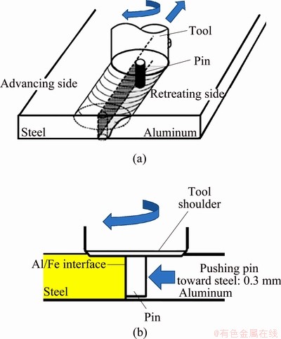
Fig. 1 Schematic of friction stir welding process (a) and position of rotating pin in present study (b)
A mild steel (St 52) sheet with the thickness of 3 mm was FSWed to a cold rolled 3003-H18 aluminum alloy sheet with the same thickness. Ultimate tensile strength (UTS) of the steel and aluminum alloy were 520 MPa and 200 MPa, respectively. To study the effects of dimension and shape of tool, two various tools were designed. The first tool (T1) consisted of a shoulder with a diameter of 24 mm and a cylindrical non-threaded pin with a diameter of 6 mm. The second tool (T2) with a diameter of 18 mm and a non-threaded conical pin was used. To prevent the overheating of aluminum alloy and reduce tool wear, the pin was inserted into aluminum alloy with an offset from the centerline of the weld. It was shifted toward the steel faying surface by a distance of 0.3 mm (0.3 mm offset). During the process, aluminum alloy and mild steel sheets were positioned in retreating and advancing sides, respectively.
Tensile test specimens were machined from the welds perpendicular to the weld line. To remove flash from the top surface and unwelded region on the underside, the specimens were machined about 0.5 mm from the both top and underside. The weld areas were located in the center of the test specimens. The lists of various friction stir welding tests and related tensile strength are summarized in Table 1.
Table 1 Summary of welding parameters and mechanical properties

Metallographic studies were conducted by scanning electron microscopy (SEM) and X-ray diffraction (XRD) techniques. SEM was equipped with an energy dispersive X-ray spectroscopy (EDS) apparatus. An X-ray diffractometer (XRD) was used to examine the structure and intermetallic layers formed in the weld zone and at the Al/Fe interface.
3 Results and discussion
3.1 Effect of tool rotation and welding speed on UTS
To investigate the effect of tool rotation speed on the tensile strength of joint, all welding tests were carried out at the welding speed of 12 mm/min. The rotation speed was varied from 450 to 700 r/min. The most ultimate tensile strength (UTS) of the weld was achieved for weld No. S1 (112 MPa), which is higher than that of the annealed aluminum base metal (i.e. 96 MPa). By increasing the tool rotational speed to 560 r/min in weld No. S2, the UTS of the joint decreased to 76 MPa. At the pin rotation speed of 700 r/min, the joint strength decreased drastically, creating an unacceptable joint.
The microstructure observation of the weld No. S3 revealed a large defect in the fracture location (see section 3.4). KIM et al [19] reported that the large defect formation is a result of excess heating and insufficient mixing of plasticized material. Therefore, to examine the effect of tool traverse speed on the tensile strength of the joints, the welding tests were carried out with welding speeds of 20 and 30 mm/min. The UTS of welds No. S3, S4 and S5 are shown in Table 1. The results show that by increasing the tool traverse speed from 12 to 30 mm/min, the UTS increased from 28 MPa (weld S3) to 97 MPa (weld No. S4) and reached 100 MPa (weld No. S5). The reason of such increase in UTS is attributed to the dependency of tensile strength with the weld heat input as discussed below.
3.2 Determination of heat input factor
In order to define the optimum welding conditions for an acceptable joint and to study the formation of intermetallic compounds and also microstructure evolution in the dissimilar weld joints, it is necessary to investigate the relationship between the joint strength and the heat input for each welding condition. Several equations were developed to describe the effects of FSW parameters on the extent of heat flow into the welding zone in Refs. [13-17]. As indicated before, by neglecting the heat from plastic deformation and tool pin, the model in Ref. [15] is similar to that in Ref. [13]. So, the authors chose the model proposed by FRIGAAD et al [13] for frictional heat generation per unit area and time during FSW process:
Q0=(4/3)��2��p��R3 (1)
where Q0 is the net power (W), �� is the friction coefficient, p is the applied pressure (Pa), �� is the tool rotation speed (r/s), and R is the tool shoulder radius (m). Unfortunately, the models cannot directly be used to investigate the influence of the welding speed. Since the tool moves during friction stir welding, the heat flows into the weld zone and the heat input per unit length of the weld can be evaluated by Q0/v, where v is the tool traverse speed (m/s). In this study, we could not measure the real pressure in the vertical direction in the work surface, and also the friction coefficient at each welding temperature. Furthermore, TANAKA et al [10] and HIRATA et al [20] reported that the relationship between the heat input and the properties of FSWed joint can be expressed without using parameters of �� and P. SCHMIDT et al [15] reported that the experimental heat generation was not proportional to the experimental applied pressure. Therefore, by eliminating �� and P from Eq. (1) and dividing both sides of the result by v, the ��heat input factor�� can be expressed as
Q0/v=(4/3)��2��R3/v (2)
3.3 Effect of heat input factor on joint properties
The calculated heat input factor (HIF) of specimens based on Eq. (2) and the variation of UTS as a function of heat input factor are illustrated in Fig. 2. Considering the identical welding speed line in Fig. 2, it is found that the heat input produced during friction stir welding process reduces the effect of strain hardening aspects of cold working, thus, the ultimate tensile strength of the work-hardened base alloy decreases from 200 MPa to 112 MPa in weld No. S1. It is necessary to note that the strength of the annealed base alloy 3003 is 96 MPa. The results show that the fracture location of weld No. S1 was at the TMAZ of aluminum (Fig. 3), suggesting an acceptable strength at the Al/Fe interface. The maximum temperature during friction stir welding of various aluminum alloys is found to be within (0.6-0.9)Tm (Tm is the melting temperature) as reported by MISHRA and MA [21] and TANG et al [17]. CHEN and KOVACEVIC [11] reported that the maximum temperature during FSW of aluminum alloy to steel reached 500 ��C. Thus, it can be summarized that the maximum temperature during the present study readily reached 500 ��C or higher. This maximum temperature is higher than the hot working temperature of 3003 alloy. The 3003 aluminum alloy is a non-heat treatable aluminum alloy. It is well known that the only way to improve the strength of such alloys is strain hardening through cold working, as reported by POLMEAR [22]. The UTS of the 3003 Al alloy is 200 MPa, meaning that the base alloy was in an extremely work hardened state. The combined effect of heat flow and deformation of material beneath the tool shoulder, which is the result of mixing action of rotating tool, eliminates all aspects of cold working such as dislocation tangles, sub-structure, grain boundaries, strained grains, through dynamic recrystallization regime. Therefore, the strength of the joints decreased. It is well accepted that dynamic recrystallization during friction stir welding of non-heat treatable aluminum alloys results in the generation of fine grains in weld nuggets, as reported by HIRATA et al [20] and MISHRA and MA [21]. High temperature produced at the TMAZ and HAZ caused change of the cold work microstructure to partially annealed material. This mater in turn caused reducing the tensile strength of the TMAZ and then fracture occurred at the TMAZ. PEEL et al [23] reported that the UTS of joints in FSW of the work hardened 5083-H19 alloy decreased to the annealed strength of base alloy due to heating cycle of process and then fracture occurred at retreating side TMAZ.
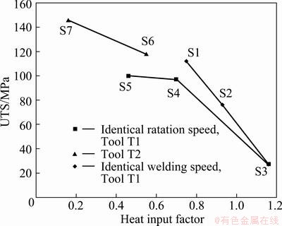
Fig. 2 Ultimate tensile strength of welds as function of heat input factor
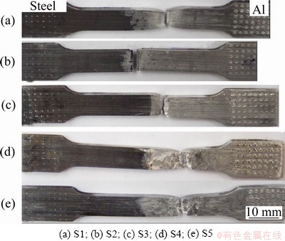
Fig. 3 Fracture locations of welds
Tensile strength of specimen S2 was found to be lower than that of the annealed aluminum base alloy (i.e. 96 MPa). The fracture location of sample S2 was at the Al/Fe interface (Fig. 3(b)). However, for weld S3, though fracture occurred at the TMAZ (Fig. 3(c)), it showed the weakest joint strength due to producing large tunneling defect in the weld (see section 3.4). In welds No. S2 and S3 which were performed under higher HIF than other welds (Fig. 2), the reduction in strength below the annealed strength of aluminum base alloy is attributed to the formation of thick intermetallic layer at the Al/Fe interface and defects formation, respectively (see section 3.4).
According to Fig. 2, it is apparent that the UTS enhanced significantly and reached a plateau by decreasing the HIF (<0.8) due to the increase in the welding speed. The tensile strength of welds S4 and S5 were similar to the strength of the annealed base alloy and tensile fracture occurred at the TMAZ (Figs. 3(d) and (e)). Figures 3(a), (d) and (e) show the 45�� fracture surface.
Since the UTS of the annealed aluminum alloy is about 96 MPa, according to Fig. 2, the relative HIF for UTS of the annealed aluminum alloy (i.e. 96 MPa) is obtained as about 0.8. It can be summarized that at HIF higher than 0.8 the UTS of the joint reduces as a result of thick intermetallic layer at Al/Fe interface and/or defect formation in weld zone. At HIF lower than 0.8, the UTS of the joints is obtained to be equal to or higher than the strength of 3003-O aluminum alloy. However, the UTS is still lower than the strength of work-hardened 3003-H18 aluminum alloy due to the elimination of work hardening aspects of base alloy by heating cycle of process. Therefore, the HIF of 0.8 can be considered the critical HIF value.
3.4 Microstructure evolution
Figure 4 illustrates the SEM photographs of the cross-sections of welds S1, S2 and S3. It is obvious that all nuggets are filled with large fragments of steel and small platelets sheared off from the steel plate, which is believed to be a result of the abrasion, wear and shearing by tool rotating action. According to Fig. 4(a), no tunnels or voids are produced in the microstructure of weld S1. Figure 4(b) shows the microstructure of weld S2. Several defects, which are pointed by arrows, can be seen in the microstructure. In Fig. 4(c), a large defect can be seen in the weld zone. According to Fig. 2, it is evident that the weld S3 has the most HIF. Therefore, due to the excessive fluidity of plastic material the tool cannot fill the weld zone with plasticized material, so tunnel defect is formed. KIM et al [19] reported the formation of tunnel defect in welds which were performed with high rotation and low traverse speed (i.e. high heat input of the weld). It is necessary to note that by decreasing the heat input, the large tunnel in weld S1 changed to the scattered voids in weld S2, as shown in Fig. 4(b).
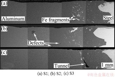
Fig. 4 SEM photographs of cross-section of welds showing Fe fragments and defects in weld zone of specimen
Figure 5 shows high magnification SEM images of the Al/Fe interface in welds S1 and S2, respectively. It is necessary to note that the tiny cavities in Fig. 5(b) are the result of etching solution and do not relate to the friction stir process. From Fig. 5(a), it can be seen that a continuous intermetallic layer exists at the Al/Fe interface. In addition, scattered particles of intermetallic compound (IMC) exist in the weld nugget. The results of EDS quantitative analyses of points 1 and 2 in Fig. 5(a) are (71.66% Al, 28.34% Fe) and (87.23% Al, 9.41% Fe, 3.36% Mn in mole fraction), respectively. The atomic ratios of Al to Fe at points 1 and 2 are 2.52 and 6.8, respectively. Therefore, it is probable from the analysis and Al-Fe phase diagram [2] that the phases are likely to be Al5Fe2 and Al 6(Fe,Mn). The XRD spectrum of weld S1 represents the existence of Al5Fe2 and Al 6Fe intermetallic phases in the weld zone (Fig. 6). Al5Fe2 also was found in the weld zone of FSWed 1100 Al alloy to low carbon steel and FSWed 5052 Al alloy to mild steel, as reported by ELREFAEY et al [24] and FUKUMOTO et al [25], respectively. The chemical composition of the indicated points in Fig. 5(b) was analyzed by EDS. The intermetallic compounds at the Al/Fe interface and scattered particles in the weld zone were identified as Al5Fe2 and Al6(Fe,Mn). The XRD results confirmed the existence of these phases in the microstructure of weld S2, but the speetrum is not shown here.

Fig. 5 Enlarged SEM images of intermetallic compound layer and scattered particles in welds

Fig. 6 XRD spectrum of weld S1 illustrating existence of Al5Fe 2 and Al6Fe
The rubbing action of the tool causes shearing off and scattering the Fe fragments from the steel plate in the weld zone. In addition, the pin rotating action results in re-breaking and redistribution of Fe fragments and causes turning them to tiny particles in the weld zone. The tiny particles react with aluminum matrix to create Al6(Fe,Mn). The thickness values of IMC layer at the Al/Fe interface of welds S1 and S2 are 4.1 and 7.8 ��m, respectively. According to Fig. 2, due to the higher HIF of weld S2, the thicker continuous IMC layer is formed at the Al/Fe interface which gives rise to fracturing at the interface. The Al-Fe intermetallics are very hard and brittle; therefore the formation of such intermetallics in weld zone degrades the properties of the joint. In joining aluminum alloy to steel, there is a contradiction between literatures on the optimum thickness of IMC layer. It was reported that the thickness of IMC layer below 5 ��m [26] or 10 ��m [27,28] was not harmful to welding aluminum alloy to steel. This study shows that at IMC thickness of 7.8 ��m the Al/Fe interface is weak (weld S2), whereas at IMC thickness of 4.1 ��m the Al/Fe interface has enough strength and fracture occurs at TMAZ (weld S1). The comparison between the thicknesses of IMC in welds S1 and S2 and their relative HIFs shows that the increase in the HIF of weld S1 by 20% results in the increase of IMC thickness by a factor of 90% in weld S2. This mater shows that there is a critical heat input factor (HIF) above which the IMC grows rapidly and joint strength decreases drastically. As described in section 3.3, by extrapolating the results on Fig. 2, the critical HIF value is considered to be 0.8 in which the welds show UTS of annealed 3003-O aluminum alloy.
The microstructures of welds S4 and S5 are similar to those of the other welds and not presented here. It is necessary to note that a continuous layer of intermetallic compound was formed at the Al/Fe interface identified as Al5Fe2 (the EDS analysis is not shown here). It is worthy to note that by increasing the welding speed from 12 mm/min (weld S3) to 20 mm/min (weld S4), the large tunnel is eliminated.
3.5 Effect of tool geometry
As Table 1 presents, the welding conditions of welds S3 and S6 were similar. However, the weld S6 was performed by the Tool T2. Tool T2 has a narrower shoulder and conical pin compared with Tool T1. Table 1 shows that the strength of weld S6 is significantly higher than that of weld S3. According to Fig. 2, the heat input factor (HIF) of weld S6 was almost 50% smaller than that of weld S3, and therefore lower temperature was produced for weld S6 compared to that for weld S3. This in turn shows that the effect of cold working was more preserved in sample S6 than in sample S3. Therefore, higher strength was obtained. The joint strength of weld S6 reached 118 MPa. However, it is interesting to note that the weld S6 fractured almost at the Al/Fe interface. A thin layer of intermetallic compound was found at upper region of the Al/Fe interface (Fig. 7(a)). The Al5Fe2 was found at the Al/Fe interface and scattered particles of Al6(Fe,Mn) were produced in the weld zone of samples. Figure 7(b) shows that no layer of intermetallic phase was formed at the bottom region of the faying surfaces and no bonding between aluminum and steel was visible at the weld root. However, the intermetallic particles of Al6(Fe,Mn) existed in the bottom region of the weld (Fig. 7(b)).
The investigation of fracture in weld S6 reveals that the cracking initiated from the bottom region of Al/Fe interface and then propagated in a straight line through interface until reached the upper region of the weld. The cross-section of the fractured specimen shows that the aluminum bonded to steel in the upper region of the weld; however, there was no noticeable bonding between aluminum and steel at the bottom region of the weld. As stated above, this weld was performed by a conical pin. In friction stir butt welds the cross-sections of butting surfaces are generally rectangular due to ease of preparation. Therefore, considering the rectangular cross- section of steel plate and also the conical shape of the pin and performed offset, it can be suggested that the conical pin just rubs the faying surface of the steel plate at the upper region of the joint and results in strong bonding between aluminum and steel. In dissimilar FSW of 5083 Al alloy to mild steel, WATANABE et al [9] reported that it is necessary to push rotating pin toward Fe faying surface to remove oxide film for obtaining a sound joint.

Fig. 7 SEM images of weld S6
It is expected that the weld tensile strength can be increased by decreasing the heat input of the weld zone. Therefore, weld S7 was performed by a tool similar to Tool T2 except having a cylindrical pin. The maximum ultimate tensile strength of 146 MPa was obtained for weld S7. Due to the low heat input of weld S7, the thickness of intermetallic layer at the Al/Fe interface decreased to 0.8 ��m and also the strain hardened features of base alloy were eliminated slightly. Therefore, the tensile strength of the weld S7 increased and reached 73% of the work hardened alloy and 153% of the annealed aluminum base alloy.
The results show that there is a maximum HIF (0.8) for FSW of 3003 Al alloy to steel, above which the joint strength is decreased due to the formation of thick IMC and/or defects. In spite of using different process parameters, in HIF range of 0.4 to 0.8, the UTS values of welds are almost similar. In this range the 3003-H18 aluminum alloy is annealed and therefore the joint strength is controlled by annealed TMAZ. At lower HIF (0.2-0.4), the joint strength is controlled by the Al/Fe interface and the fracture occurs at the interface. The comparison between the HIF of welds S1 and S7 and their IMC thickness shows good conformity between HIF and IMC thickness. The comparison between microstructure and strength of the welds shows the good conformity between the results and the calculated ��heat input factor�� based on Eq. (2), so this equation can be used to predict the range of process parameters in dissimilar FSW where the properties of base alloys are incompatible. As an empirical result, to incorporate the effect of welding speed, it is possible to divide the value of heat input model on welding speed to optimize the welding parameters, as shown in this research.
4 Conclusions
Dissimilar friction stir welds between 3003-H18 aluminum alloy and plain carbon steel were obtained with different tool rotation speed, tool traverse speed and tool design. The defect free joints were obtained. The results can be concluded as follows.
1) The heat input model which was developed for similar FSW was simplified and used for FSW of dissimilar materials such as aluminum and steel. The various FSW process parameters were investigated to assess the heat input model. The comparison between the microstructure, thickness of IMC and strength of welds shows the good conformity between the results and the calculated heat input factor (HIF). The joint strength and fracture location are controlled by Al/Fe interface in HIF range of 0.2-0.4, by strength of TMAZ in HIF range of 0.4-0.8 and by thick IMC and/or defect formation at HIF>0.8.
2) The results showed that at constant welding speed, increasing the tool rotation speed from 450 to 700 r/min increased the heat input of the weld zone and tunnel and cavity were formed, which resulted in reduction in ultimate tensile strength of the joints from 112 MPa to 28 MPa.
3) At constant rotation speed, the ultimate tensile strength increased from 28 MPa to 100 MPa by decreasing the heat input factor because of the increase in the welding speed.
4) The results showed that if annealing occurred at the weld zone, the strength of the joint would reduce.
5) The fracture locations of welds were found to be a function of heat input and pin geometry. At the highest heat input, the tensile fracture occurred at the aluminum TMAZ as a result of large tunnel formation. By decreasing the heat input, fracture occurred at the Al/Fe interface where a thick layer of Al 5Fe2 was found. More reduction in heat input resulted in fracturing at the TMAZ.
6) A continuous layer of intermetallic compound at aluminum/steel faying surface was found to be Al 5Fe2. Al6(Fe,Mn) intermetallic compound was found in the weld nugget as scattered particles.
7) The thickness of intermetallic layer increased from 0.8 ��m to 7.8 ��m by increasing the heat input factor. Using narrower shoulder noticeably reduced the weld heat input and therefore ultimate tensile strength of the joint increased to 146 MPa.
8) The study shows that conical pins are not suitable for welding aluminum to steel with rectangular cross section for butt joints due to producing no interaction between steel faying surface and conical pin at the bottom region of the weld.
Acknowledgments
The authors gratefully acknowledge Dr. M. G. MARAGHEH and Mr. M. PANAHI for their staunch support and providing the welding machine.
References
[1] CARDARELLI F. Materials handbook: A concise desktop reference [M]. 2nd ed. London: Springer-Verlag London Ltd., 2008: 32.
[2] BAKER H. ASM handbook. Vol. 3: Alloy phase diagrams [M]. 10th ed. Ohio: ASM International, 1992: 44.
[3] ELLIOTT S, WALLACH E R. Joining aluminum to steel. Part 1: Diffusion bonding [J]. Metal Construction, 1981, 3: 167-171.
[4] PAVENTHAN R, LAKSHMINARAYANAN P R, BALASUBRAMANIAN V. Prediction and optimization of friction welding parameters for joining aluminum alloy and stainless steel [J]. Transactions of Nonferrous Metals Society of China, 2011, 21(7): 1480-1485.
[5] WATANABE T, SAKUYAMA H, YANAGISAWA A. Ultrasonic welding between mild steel sheet and Al-Mg alloy sheet [J]. Journal of Materials Processing Technology, 2009, 209(15-16): 5475-5480.
[6] SIERRA G, PEYRE P, DESCHAUX-BEAUME F, STUART D, FRAS G. Steel to aluminum key-hole laser welding [J]. Materials Science and Engineering A, 2007, 447(1-2): 197-208.
[7] THOMAS W M, NICHOLAS E D, NEEDHAM J C, MURCH M G, TEMPLESMITH P, DAWES C J. Friction stir butt welding: US patent No. 5460317 [P]. 1995.
[8] UZUN H, DALLE DONNE C, ARGAGNOTTO A, GHIDNI T, GAMBARO C. Friction stir welding of dissimilar Al 6013-T4 to X5CrNi18-10 stainless steel [J]. Materials and Design, 2005, 26(1): 41-46.
[9] WATANABE T, TAKAYAMA H, YANAGISAWA A. Joining of aluminum alloy to steel by friction stir welding [J]. Journal of Materials Processing Technology, 2006, 178(1-3): 342-349.
[10] TANAKA T, MORISHIGE T, HIRATA T. Comprehensive analysis of joint strength for dissimilar friction stir welds of mild steel to aluminum alloys [J]. Scripta Materialia, 2009, 61(7): 756-759.
[11] CHEN C M, KOVACEVIC R. Joining of Al 6061 alloy to AISI 1018 steel by combined effects of fusion and solid state welding [J]. International Journal of Machine Tools and Manufacture, 2004, 44(11): 1205-1214.
[12] LEE W B, SCHMUECKER M, ALFARO MERCARDO U, BIALLAS G, JUNG S B. Interfacial reaction in steel�Caluminum joints made by friction stir welding [J]. Scripta Materialia, 2006, 55(4): 355-358.
[13] FRIGAAD  GRONG MIDLING O T. A process model for friction stir welding of age hardening aluminum alloys [J]. Metallurgical and Materials Transactions A, 2001, 32(5): 1189-1200.
[14] HEURTIER P, JONES M J, DESRAYAUD C, DRIVER J H, MONTHEILLET F, ALLEHAUX D. Mechanical and thermal modeling of friction stir welding [J]. Journal of Materials Processing Technology, 2006, 171(3): 348-357.
[15] SCHMIDT H, HATTEL J, WERT J. An analytical model for the heat generation in friction stir welding [J]. Modelling and Simulation in Materials Science and Engineering, 2004, 12(1): 143-157.
[16] NANDAN R, ROY G G, LIENERT T J, DEBROY T. Three-dimensional heat and material flow during friction stir welding of mild steel [J]. Acta Materialia, 2007, 55(3): 883-895.
[17] TANG W, GUO X, MCCLURE J C, MURR L E, NUNES A. Heat input and temperature distribution in friction stir welding [J]. Journal of Materials Processing and Manufacturing Science, 1998, 7(2): 163-172.
[18] ZHANG X X, XIAO B L, MA Y Z. A transient thermal model for friction stir weld. Part I: The model [J]. Metallurgical and Materials Transactions A, 2011, 42(10): 3218-3228.
[19] KIM Y G, FUJII H, TSUMUR T, KOMAZAKI T, NAKATA K. Three defect types in friction stir welding of aluminum die casting alloy [J]. Materials Science and Engineering A, 2006, 415(1-2): 250-254.
[20] HIRATA T, OGURI T, HAGINO H, TANAKA T, CHUNG S W, TAKIGAWA Y, HIGASHI K. Influence of friction stir welding parameters on grain size and formability in 5083 aluminum alloy [J]. Materials Science and Engineering A, 2007, 456(1-2): 344-349.
[21] MISHRA R S, MA Z Y. Friction stir welding and processing [J]. Materials Science and Engineering R, 2005, 50(1-2): 1-78.
[22] POLMEAR I J. Light alloys: From traditional alloys to nanocrystals [M]. Elsevier Ltd, 2005: 32-36.
[23] PEEL M, STEUWER A, PREUSS M, WITHERS P J. Microstructure, mechanical properties and residual stresses as a function of welding speed in aluminum AA5083 friction stir welds [J]. Acta Materialia, 2003, 51(16): 4791-4801.
[24] ELREFAEY A, GOUDA M, TAKAHASHI M, IKEUCHI K. Characterization of aluminum/steel lap joint by friction stir welding [J]. Journal of Materials Engineering and Performance, 2005, 14(1): 10-17.
[25] FUKUMOTO S, TSUBAKINO H, OKITA K, ARITOSHI M, TOMITA T. Amorphization by friction welding between 5052 aluminum alloy and 304 stainless steel [J]. Scripta Materialia, 2000, 42(8): 807-812.
[26] ELLIOTT S, WALLACH E R. Joining aluminum to steel. Part 2: Friction welding [J]. Metal Construction, 1981, 4: 221-225.
[27] LIN San-bao, SONG Jian-ling, MA Guang-chao, YANG Chun-li. Dissimilar metals TIG welding-brazing of aluminum alloy to galvanized steel [J]. Frontiers of Materials Science in China, 2009, 3(1): 78-83.
[28] PEYRE P, SIERRA G, DESCHAUX-BEAUME F, STUART D, FRAS G. Generation of aluminum-steel joints with laser-induced reactive wetting [J]. Material Science and Engineering A, 2007, 444(1-2): 327-338.
����Ħ�����ӹ��ղ����ͽ���ͷ���γߴ��3003-H18���Ͻ�͵�̼�ֺ������ܵ�Ӱ��
M. DEHGHANI, S. A. A. AKBARI MOUSAVI, A. AMADEH
School of Metallurgy and Materials Engineering, College of Engineering, University of Tehran, Tehran, P.O. Box 11155-4563, Iran
ժ Ҫ�����ý���Ħ�������ն�3 mm��3003-H18���Ͻ�͵�̼�ְ���к��ӣ��������ȱ�ݵĶԽӺ���ͷ����һ��������ͬ�ֽ�������Ħ��������������ģ�ͽ��м��������о����ֽ�������Ħ�������ٶȡ���ת�ٶȺͽ���ͷ���ֱ���Ժ�����֯�����ܵ�Ӱ�졣�Ժ�����֯�������仯����ͽ�ͷǿ�ȵıȽϱ�����ʵ������ͨ����ģ�ͼ���õ���������������(HIF)�ǺϽϺá���HIFֵ����0.2~0.4֮��ʱ�����ӽ�ͷǿ����Al/Fe����Ŀ��ƣ���HIFֵ����0.4~0.8֮��ʱ����ǿ����������ѧӰ����ǿ�ȵĿ��ƣ���HIF>0.8ʱ����ǿ���ܽ����仯�����ȱ�ݵĿ��ơ�
�ؼ��ʣ�����Ħ�������������ӣ�����֯������ǿ�ȣ����Ͻ𣻵�̼�֣������仯����
(Edited by Sai-qian YUAN)
Corresponding author: S. A. A. AKBARI MOUSAVI; Tel: +98-21-82084096; Fax: +98-21-88006076; E-mail: akbarimusavi@ut.ac.ir
DOI: 10.1016/S1003-6326(13)62683-7
Abstract: Defect-free butt joints of 3003 Al alloy to mild steel plates with 3 mm thickness were performed using friction stir welding (FSW). A heat input model reported for similar FSW was simplified and used to investigate the effects of welding speed, rotation speed and tool shoulder diameter on the microstructure and properties of dissimilar welds. The comparison between microstructure, intermetallics and strength of welds shows the good conformity between the results and the calculated heat input factor (HIF) achieved from the model. The joint strength is controlled by Al/Fe interface at HIF of 0.2-0.4, by TMAZ at HIF of 0.4-0.8 and by intermetallics and/or defects at HIF>0.8.
