
Trans. Nonferrous Met. Soc. China 30(2020) 1169-1182
Effects of melt spinning process parameters and wheel surface quality on production of 6060 aluminum alloy powders and ribbons
Sultan OZTURK1, Sefa Emre SUNBUL1,2, KUrSat ICIN1
1. Department of Metallurgical and Materials Engineering, Karadeniz Technical University, Trabzon, Turkey;
2. Department of Metallurgical and Materials Engineering, Gaziantep University, Gaziantep, Turkey
Received 1 August 2019; accepted 17 February 2020
Abstract:
The aim of this study is to investigate the surface quality of the melt spinning wheel, which was changed from smooth type to textured structure, to atomize liquid metal to form powders. The effects of melt spinning process parameters like wheel speed, gas ejection pressure, molten metal temperature, nozzle�Cwheel gap and wheel surface quality on the morphological and microstructural features of 6060 aluminum alloy powders and ribbons were investigated. It was observed that ribbon type material was obtained with the smooth wheel and the powder was produced with textured type. The sizes of produced ribbons with smooth surface wheel varied in the range of 30-170 ��m in thickness, 4-8 mm in width, and 0.5-1 m in length. The average powder size of the powders manufactured using the textured wheel was in the range of 161-274 ��m, depending on the process parameters. Increasing the wheel speed, melt temperature and decreasing gas ejection pressure, nozzle-wheel gap resulted in the decrease of both ribbon thickness and powder size. The microstructures of the powders and ribbons were the equiaxed cellular type, and the average grain sizes diminished with decreasing the ribbon thickness and powder size. The maximum cooling rates were 2.00��105 and 1.26��104 K/s for the ribbon with thickness of 30 ��m and for the powder with size of 87 ��m, respectively.
Key words:
melt spinning method; 6060 aluminum alloy; process parameters; textured wheel;
1 Introduction
Material scientists have been striving for many decades to develop new materials which are stronger, stiffer, more ductile and lighter than conventional materials. New materials require low processing cost and show unique properties of high tensile strength, high stiffness and low density. Improved properties can lead to extended lifetime, energy savings and cost reduction. One way of achieving the above objectives is to use rapid solidification technique [1,2]. Rapid solidification process has distinct advantages over conventional ingot metallurgy to meet the increasing demand for high performance materials [1,3]. It is widely believed that rapid solidification processing can fabricate metallic alloys with better physical and mechanical properties. The unique properties of rapidly solidified alloys with metastable structures make this class of materials attractive both for fundamental research and for numerous industrial applications [1,4-8]. There are many advantages of rapid solidification technique and some of them have the ability to form novel metastable crystalline and amorphous phases, increase solubility limits of alloying elements, excellent homogeneity due to extremely low level of segregation, and refine the structure to nanocrystals and nanoparticles [9-12]. Rapid solidification method is particularly attractive for aluminum alloys because solid solubility of alloying elements is limited and can be extended via rapid solidification process [3,13]. The extended solid solution and formation of the second phase particles improve the strength, wear resistance and thermal stability of these alloys [7,10].
The melt spinning method is one of the well-known techniques among various rapid solidification methods developed over the past few decades. This process is the most common technique that can significantly modify the structure of material [9,14]. It has also gained much importance commercially and it is the most popular method in both academic and industrial perspectives due to its mass production capability to produce wide, thin, and uniform ribbons directly from the melt with good surface finish. The process is used extensively for production of various kinds of metallic alloy ribbons. In this process, the metal is firstly melted in a crucible by induction heating and then the molten metal is ejected through a nozzle and impinges on a rotating wheel. The narrow spacing between the nozzle end and the wheel surface causes a puddle to form. Upon contacting, the molten metal rapidly solidifies, and a continuous ribbon is removed from the puddle. Formation of continuous ribbon is achieved when a dynamic equilibrium is established in the puddle. Several process parameters such as wheel speed, melt temperature, nozzle-wheel gap and ejection pressure influence the size and shape of produced ribbons [15-23].
The 6060 aluminum alloy contains magnesium and silicon as major addition elements. This alloy exhibits excellent formability, satisfactory strength, weldability, good surface properties, and a relatively good corrosion resistance. Proper combination of these properties makes this alloy commercially very attractive and candidate material for various utilizations such as applications in aerospace, body sheets in automotive industry, electrical and electronic industries. The 6060 aluminum alloy has been studied extensively because of its technological importance and increase in strength by precipitation hardening heat treatment [3,7,24-28].
In the present study, production of 6060 aluminum alloy ribbons by melt spinning method and effects of primary process control parameters such as wheel speed, gas ejection pressure, and distance from nozzle end to wheel surface on the sizes of the ribbons were investigated. For this purpose, a number of experimental runs were performed. On the other hand, as it is well known that the production of ribbon with melt spinning method is an interim process and these ribbons are subjected to secondary processing routes such as high energy ball milling to obtain useful powders. This process needs more energy and time and increases production cost. It is clear that obtaining powder directly from melt spinning method will reduce manufacturing cost and shorten processing routes. Taking into consideration of these facts, production of powder with melt spinning method was performed. For this purpose, the surface quality of melt spinning wheel was changed from smooth type to textured structure to atomize liquid metal to form powders. In use of the textured surface wheel, the melted metal impinges to textured surface wheel, and so powders are formed with different sizes. Above mentioned melt spinning process parameters such as wheel speed, gas ejection pressure, and distance from nozzle end to wheel surface were also experienced for powder production.
2 Experimental
The material used in this study is 6060 aluminum alloy with the following nominal composition (wt.%): 0.35-0.6 Mg, 0.3-0.6 Si, 0.1-0.3 Fe, 0.15 Zn, 0.1 Cu, 0.1 Ti, 0.1 Mn, 0.05 Cr, Al bal. The experiments were performed using a laboratory scale single roller melt spinning device operating in 1��10-5 Pa vacuum atmosphere (Fig. 1). During the experimental trials, one parameter was changed while others were kept constant. Each run was carried out by melting the alloy in a boron nitride crucible having rectangular slit shape. The length and width of the slit shape nozzle were kept constant with 10 mm �� 0.6 mm. Four different wheel speeds of 26, 34, 43 and 52 m/s were employed to study the effect of wheel speed on the sizes of the ribbons and powders. The distances from nozzle end to the wheel surface were chosen as 1, 2, 3 and 4 mm. Four different melt temperatures of 700, 750, 800 and 850 ��C were examined. Gas ejection pressures of 0.6��105, 0.8��105, 1.0��105 and 1.2��105 Pa were used to investigate the effect of gas pressure on the sizes of ribbons and powders. The temperature of the melt was controlled by an infrared thermometer positioned on top of the crucible. Quench wheel which had 40 mm in width, 270 mm in diameter and made of copper, was rotated using an external AC motor and the tangential speed of wheel was controlled by a digital control unit placed out of the chamber. Before each run, the chamber was evacuated by a turbomolecular pump up to 1��105 Pa and backfilled with high purity argon gas and then evacuated to maximum vacuum to wipe out the air. The melted alloy was ejected through the nozzle onto the rotating wheel by introducing high purity (99.999%) argon gas flow with different pressures given above through the hexagonal boron nitride crucible.
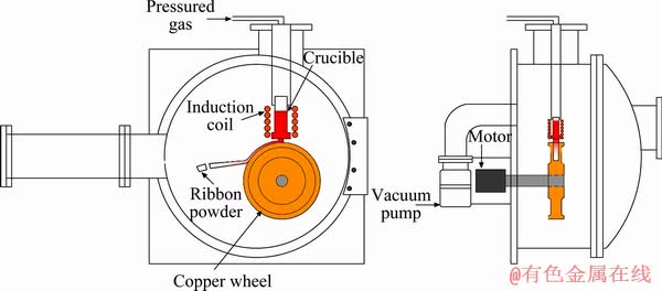
Fig. 1 Schematic illustration of melt spinning device
In the present study, different from studies made in Refs. [8,16,19], the surface structure of the melt spinning wheel was changed from smooth type to textured form to search the effect of wheel surface quality on the shape and structural properties of resultant product. As shown in Fig. 2, the textured wheel has teeth on the surface and in this respect, it looks like a gear. In this sense, the main objective with this type of wheel surface is to produce powder directly instead of ribbon by atomization mechanism. When the liquid metal contacts with the wheel surface, it enters the gaps among teeth and easily adheres the surface through the teeth. The centrifugal energy of the wheel is transferred to the liquid metal by way of strong adherence of the liquid metal to the wheel surface and finely it is atomized into droplets and solidifies to form powder.
The morphologies and the microstructural properties of the produced ribbons and powders were analyzed by using SEM (Zeiss model). Samples were cold mounted in a two-component epoxy resin for microstructural examinations. The mounted specimens were ground with 1000, 1200 and 1500 grit sandpapers. Then, these samples were polished with 1 ��m and 0.25 ��m diamond solution. The prepared samples were etched with sodium hydroxide solution (10 g sodium hydroxide and 90 mL distilled water) for 20-90 s. The phases in the melt-spun powders and ribbons were characterized by X-ray diffraction (XRD) apparatus of Panalytical X��pert3 powder model with Cu K�� radiation. The mean particle sizes and size distributions of melt spun powders were analyzed by laser particle size analyzer of Malvern Mastersizer Hydro 2000 model.
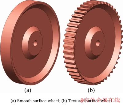
Fig. 2 Surface morphologies of melt spinning wheels
3 Results and discussion
Photo images of melt spun ribbons produced under different processing conditions were shown in Figs. 3(a) and (b). As can be seen from the figures, the produced ribbons had continuous form and their sizes were varied with process parameters. The width, length and thickness values were 4-8 mm, 0.5-1 m and 30-170 ��m, respectively. Primarily, the ribbon thickness rather than length and width was affected significantly by process parameters.
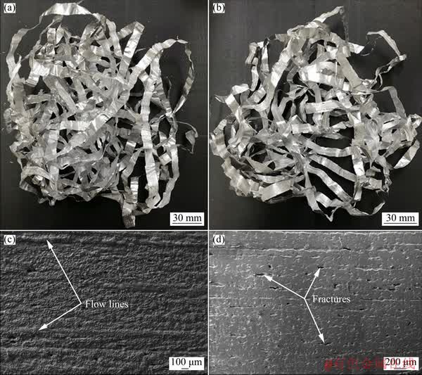
Fig. 3 Photo images of produced ribbons under different processing conditions of wheel speed of 26 m/s, gas ejection pressure of 1��105 Pa, nozzle end to wheel surface distance of 1 mm, and melt temperature of 700 ��C (a), wheel speed of 52 m/s, gas ejection pressure of 1.0��105 Pa, nozzle end to wheel surface distance of 1 mm, and melt temperature of 700 ��C (b), and surface morphologies of air side (c) and wheel side (d) of produced ribbons under processing conditions in (a)
The surface morphologies of air side (non- contact) and wheel contact of produced ribbons under processing conditions in Fig. 3(a) were shown in Figs. 3(c) and (d), respectively. Both surfaces were different from each other significantly. The wheel contact surfaces of the ribbons were relatively smooth and almost mimics the quench wheel surface. However, this surface was characterized by many fractures which were formed along flow direction during solidification process (Fig. 3(d)). These fractures resembled solidification shrinkages and they can be explained in terms of insufficient contact between the melt and wheel surface. In other words, the wheel speed was too high to give sufficient contact time for the melt to complete solidification. In this regard, the fractures represented regions of high thermal contact resistance at the wheel/melt interface as a result of poor contact between the ribbon and the wheel surface [19]. The air side (non-contact) surface of the ribbons was relatively rough and exhibited liquid metal flow lines which solidified freely running parallel to the rotation of the wheel direction and did not have any fractures (Fig. 3(c)).
As stated above, the surface structure of melt spinning wheel was changed from smooth type to textured form to search the possibility of producing powders directly instead of ribbons. As a result, powders were successfully produced. Morphologies of produced powders were shown in Fig. 4. As can be seen from Fig. 4, predominantly various shaped powders were obtained and the powder shape changed to be flaky when the powder size got larger.
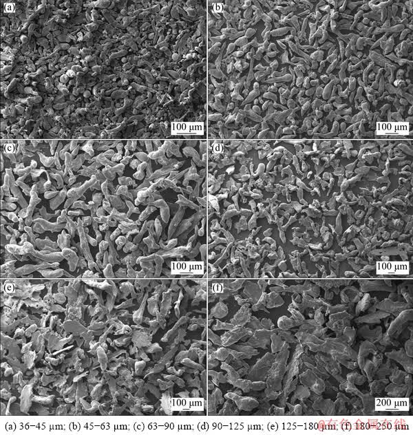
Fig. 4 Morphologies of 6060 aluminum alloy powders produced with textured surface wheel at different sieve fractions
Experimental results showed that the ribbon width and length sizes were not affected by process conditions and the melt spinning parameters virtually affected the thickness values. In order to study the influence of the processing parameters on the thickness of the melt-spun ribbons, a number of experimental trials were carried out, in which one parameter was changed while the others were kept constant. Figure 5(a) showed the variation of ribbon thickness as a function of wheel speed. During these trials, the gas ejection pressure, nozzle-wheel gap, and melt temperature were kept constant as 1��105 Pa, 1 mm, and 700 ��C, respectively. As could be seen from Fig. 5(a), the increase of wheel speed from 26 to 52 m/s resulted in the decrease of ribbon thickness from 119 to 60 ��m. This could be explained by energy which was given by liquid metal with centrifugal force effect. The thickness of melt puddle decreased due to increasing centrifugal force transferred to liquid metal with increasing wheel speed, and thin ribbons were obtained. These results were in good agreement with those results obtained by melt spinning method in Refs. [29-31].
The effect of gas ejection pressure on the thickness of the melt-spun ribbons was given in Fig. 5(b) for gas pressures of 0.6��105, 0.8��105, 1��105, and 1.2��105 Pa. The experimental trials were carried out at a wheel speed of 34 m/s, a nozzle-wheel gap of 1 mm, and a melt temperature of 700 ��C. As could be seen from Fig. 5(b), the ribbon thickness increased continuously with increasing gas ejection pressure. Similar observations have been reported in Refs. [15,16]. 56, 67, 87 and 92 ��m thick ribbons were obtained at gas ejection pressures of 0.6��105, 0.8��105, 1��105 and 1.2��105 Pa, respectively. The thickness of the melt puddle on the wheel became large with increasing gas ejection pressure and subsequently led to the increase in ribbon thickness. Melt puddle was formed over wheel associated with increasing ejection pressure. The more the molten metal mass over the wheel was, the thicker the ribbons were obtained [15,16].
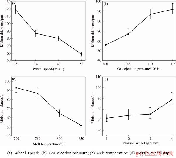
Fig. 5 Relationship between ribbon thickness and melt spinning processing parameters
Figure 5(c) showed the variation of ribbon thickness as a function of melt temperature. During these trials, the other melt spinning parameters were chosen as follows: wheel speed 34 m/s, nozzle-wheel gap 1 mm, and gas ejection pressure 1.0��105 Pa. It could be seen from Fig. 5(c) that the ribbon thickness decreased with increasing melt temperature. The average ribbon thicknesses of 93, 87, 62 and 55 ��m were obtained at melt temperatures of 700, 750, 800 and 850 ��C, respectively. It was obvious that the viscosity and surface tension of molten metal decreased with increasing temperature and this facilitated thin melt puddle on the wheel surface [32,33].
The variation of ribbon thickness with nozzle-wheel gap was given in Fig. 5(d), keeping other parameters constant (wheel speed 34 m/s, melt temperature 700 ��C, and gas ejection pressure 1��105 Pa). As could be seen from Fig. 5(d), the average ribbon thickness increased continuously with enhancing nozzle-wheel gap. The increase of the ribbon thickness might be attributed to the instability of melt puddle because the effect of gas pressure was weakened with increasing nozzle-wheel gap [34]. In other words, more stable and thinner melt puddle could be obtained with narrow nozzle-wheel gap. Ribbons with 71, 74, 77 and 88 ��m in thickness were produced with 1, 2, 3, and 4 mm nozzle-wheel gaps, respectively.
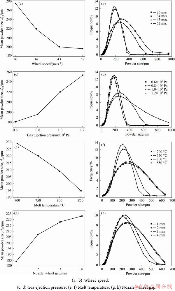
Fig. 6 Effects of process parameters on mean powder size (d50) and powder size distribution
It was well known that the melt spinning process with a smooth surface wheel was used primarily to produce thin and continuous ribbons. Different from conventional applications, powder production experiments with textured surface wheel (Fig. 2(b)) were performed in this study. One kind of atomization was implemented with textured surface wheel and powder products were achieved. This approach also made it possible to use the melt spinning device as a centrifugal atomization unit. Above mentioned melt spinning process parameters were used exactly to produce powders and to reveal the effects of these parameters on the mean powder size and size distribution. The effects of wheel speed on the mean powder size (d50) and size distribution are given in Figs. 6(a) and (b), respectively. As can be seen from Figs. 6(a) and (b), the mean powder size decreased, and powder size distribution shifted towards to lower values with increasing wheel speed from 26 to 52 m/s. This could be explained in terms of energy phenomena. The centrifugal energy of wheel increased with increasing wheel speed. As a result, the liquid metal was atomized with higher energy and finer particles were obtained. The average powder size (d50) values at wheel speeds of 26, 34, 43 and 52 m/s were found to be 274, 220, 181 and 177 ��m, respectively.
The variation of mean powder size and powder size distribution at gas ejection pressures of 0.6��105, 0.8��105, 1.0��105, and 1.2��105 Pa was represented in Figs. 6(c) and (d), respectively. The experimental runs were carried out at a wheel speed of 34 m/s, a nozzle-wheel gap of 1 mm, and a melt temperature of 700 ��C. As was the case in ribbon production, the mean particle size was coarsened with increasing gas ejection pressure. This could be attributed to increasing thickness of the melt layer on the wheel surface. The melt layer was enhanced with increasing gas ejection pressure and the centrifugal energy of the wheel was shared by more liquid metal. As a result of this, produced particles were coarsened. The d50 values at 0.6��105, 0.8��105, 1.0��105 and 1.2��105 Pa gas ejection pressures were obtained to be 161, 176, 220 and 253 ��m, respectively.
Figures 6(e) and (f) respectively showed the effects of melt temperature on the mean powder size and size distribution, keeping the wheel speed at 34 m/s, nozzle-wheel gap at 1 mm, and gas ejection pressure at 1.0��105 Pa. It could be seen that the mean powder sizes decreased rapidly with increasing melt temperature from 700 to 850 ��C. The mean powder sizes at temperatures of 700, 750, 800 and 850 ��C were found to be 229, 220, 209 and 195 ��m, respectively. This could be attributed to decreasing viscosity and surface tension values of molten metal with increasing temperature and this helped the disintegration of liquid metal to finer particles.
The effects of nozzle-wheel gap on the mean powder size and powder size distribution were given in Figs. 6(g) and (h), respectively, keeping other parameters constant (wheel speed 34 m/s, melt temperature 700 ��C, and gas ejection pressure 1.0��105 Pa). It can be observed from Figs. 6(g) and (h) that the coarse powders were obtained with increasing nozzle-wheel gap. The mean powder sizes of 184, 207, 218 and 223 ��m were obtained at nozzle-wheel gaps of 1, 2, 3 and 4 mm, respectively. The textured surface point at the contact place between wheel and liquid metal could cause this change of the average powder size from impact effect, impact speed at textured parts on wheel and spread semi-solid powders.
The microstructures of the produced ribbons with different thicknesses were given in Figs. 7(a) and (b). As could be seen from Figs. 7(a) and (b), the overall microstructure of produced ribbons was characterized by fine-grained equiaxed cells. It was also observed that the microstructure of the ribbons was not changed through the cross section of the ribbon. In other words, the distribution of the grains was homogeneous from top to the bottom of the ribbon. On the other hand, the mean cell sizes varied with ribbon thickness and smaller cell sizes were obtained with thinner ribbons. This meant that cooling rates of thinner section ribbons were higher than those of thicker ones. The mean cell sizes of 30, 41, 55 and 85 ��m thick ribbons were measured to be 0.51, 0.55, 0.63 and 0.75 ��m, respectively.
Figures 7(c) and (d) show the microstructure of the melt-spun powders obtained by means of SEM. The powder microstructure was formed as equiaxed grains as it was the case for ribbons, and the mean grain sizes varied depending on powder size. By comparing the microstructures of powders and ribbons, it was observed that ribbons had finer grain sizes than powders. The mean grain sizes for 87, 102, 128 and 160 ��m powders were measured to be 1.50, 1.59, 1.68 and 1.80 ��m, respectively.
The variation of the mean grain sizes and cooling rate of ribbons and powders was given in Figs. 7(e) and (f), respectively. Some empirical equations were proposed by different authors for the estimation of cooling rates. The following equation was used for 6xxx series of aluminum alloys [24,35,36]:
��=3.57��104 d-2.56 (1)
where �� is the cooling rate (K/s) and d is the mean grain size.
Substituting above mean grain size values into Eq. (1), the cooling rates of 30, 41, 55, and 85 ��m thick ribbons became 2.00��105, 1.65��105, 1.16��105 and 0.74��105 K/s, respectively. On the other hand, the cooling rates of 87, 102, 128 and 160 ��m powders were calculated as 1.26��104, 1.08��104, 0.95��104, and 0.79��104 K/s, respectively.
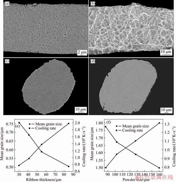
Fig. 7 Microstructures of ribbons with thicknesses of 30 ��m (a) and 55 ��m (b), and powders with sizes of 87 ��m (c) and 160 ��m (d), and variation of cooling rate and mean grain size with ribbon thickness (e) and powder size (f)
For further investigation of microstructural features of powders and ribbons, SEM, EDS and XRD analyses were employed for the ingot alloy, powders and ribbons. The microstructure of the starting 6060 alloy was examined to find out microstructural properties and phase distribution prior to melt-spinning production. Figure 8(a) showed the microstructure of the ingot alloy. It could be seen that the alloy had relatively coarse grains (mean grain size was about 80 ��m) because of slow cooling during solidification process and it consisted of two distinct phases. It was easily observed that Al-rich matrix phase dominated the microstructure and there were small amount of second phase particles of Al8Fe2Si dispersed in Al-matrix. The chemical composition of Al8Fe2Si phase determined from EDS spectra (Fig. 8(b)) was found to be 70.39 at.% Al, 9.78 at.% Si, 18.99 at.% Fe, and 0.83 at.% Mg. This analysis resulted in an Fe/Si mole ratio of 1.95, with the probable stoichiometry of Al8Fe2Si in good agreement with the accepted stoichiometry of ��-AlFeSi [37,38]. Small amount of Mg2Si phase was detected by means of XRD analysis but this phase was not visible in the SEM image.
SEM images and EDS analyses of ribbons and powders were given in Fig. 9. Contrary to three- phase structure of ingot alloy, the microstructures of powders and ribbons involved only ��(Al) phase. EDS results proved that the compositional differences between the grain interior and the grain boundary were insignificant. This suggested the extended solid solubility of Mg, Fe and Si elements in the aluminum matrix, thus creating super-saturated Al phase because of rapid solidification of the ribbons and powders during melt spinning process.
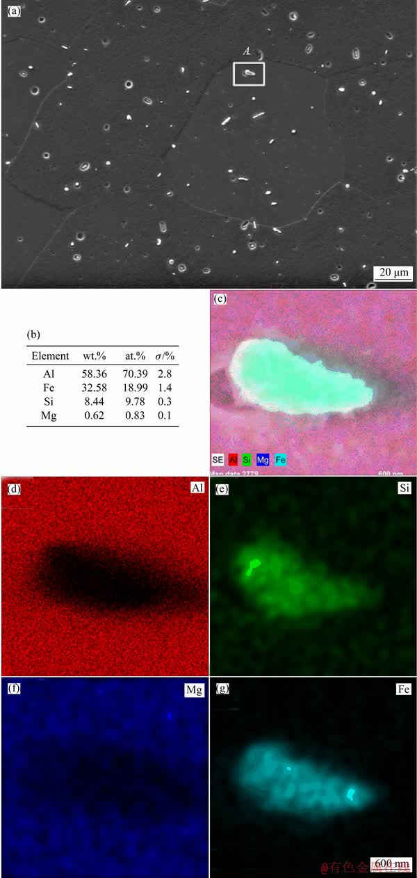
Fig. 8 SEM image of 6060 ingot alloy (a), EDS analysis results of Region A in (a) showing Al8Fe2Si phase (b), elemental mapping of Al8Fe2Si phase (c), elemental mapping of Al (d), Si (e), Mg (f) and Fe (g) (�� in (b) represents error values)
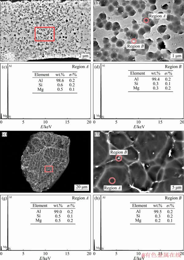
Fig. 9 SEM images of AA6060 alloy ribbon (a) and powder (e), high magnification microstructures of same ribbon (b) and powder (f), EDS spectra of grain interior (Region A in (b)) of ribbon (c) and powder (g), and EDS spectra of grain boundary (Region B in (b)) of ribbon (d) and powder (h)
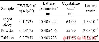
In order to investigate the effect of rapid solidification on phase structure, 6060 alloy ingot and melt-spun samples of powders and ribbons were examined by the X-ray diffraction (XRD) (Fig. 10). It is crucial to emphasize that the XRD patterns were in good agreement with micro- structures given in Fig. 9. XRD pattern of ingot alloy shows ��(Al) and intermetallic Mg2Si and Al8Fe2Si phase peaks. The obtained Mg2Si and Al8Fe2Si peaks are of very low intensities; thisindicates that the observed peaks are usually connected with low volume fractions of Mg2Si and Al8Fe2Si phases in the bulk material [39]. In the literature, the preferred orientation of the crystal may affect the peak height in a certain plane. For the 6060 ingot alloy, the diffraction peak intensity for (002) plane at 2��=44.5�� is higher than that for (111) plane at 2��=38.2��. The reason may be related to the production method of the material. Since the 6060 alloy is produced by the extrusion method, the peak intensities may vary depending on the extrusion direction [40]. High cooling rate obtained in rapid solidification has also a significant influence on phase structures of powders and ribbons. When the solidification rate increases, no intermetallic Mg2Si and Al8Fe2Si phase peaks in the melt-spun powders and ribbons are observed. This means that the solidification rate is high enough to retain most of alloying elements in the ��(Al) matrix as solid solution. High cooling rate obtained in rapid solidification has also substantial influence on the microstructure of the ��(Al) phase by increasing lattice strain. The lattice parameter of ��(Al) phase decreases with participation of Fe, Mg and Si elements in solid solution and the decrease of the size has been suggested to be related to the closest distance of Fe, Mg and Si atoms. These elements which are dissolved in ��(Al) phase are expected to decrease the equilibrium lattice parameter value for (002) plane from 0.405822 nm for ingot alloy to 0.405606 nm for melt-spun powder. Further decrease of lattice parameter of ��(Al) phase to 0.403728 nm for melt-spun ribbon was observed and it can be related to the solid solubility extension values of Fe, Mg and Si [41]. On the other hand, rapid solidification in melt spinning process has also a significant influence on the ��(Al) phase by means of increasing lattice strain. The crystallite lattice strain can be calculated from the broadening of X-ray diffraction peaks by considering the full width at half maximum (FWHM) of the all individual peaks. As can be seen from Table 1, lattice strain for (002) plane is 1.5��10-3 for ingot alloy and it increases to 2.0��10-3 and 2.5��10-3 for melt-spun powder and ribbon, respectively.
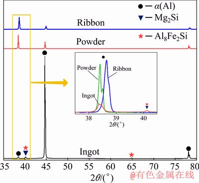
Fig. 10 XRD patterns of AA6060 ingot alloy, powders and ribbons
Table 1 Effect of cooling rate on crystal properties of AA6060 ingot alloy, powders and ribbons
4 Conclusions
(1) Increasing the wheel speed and melt temperature resulted in the decrease of both ribbon thickness and powder size of rapidly solidified AA6060 alloy. Opposite results for gas ejection pressure and nozzle-wheel gap were obtained. Higher gas ejection pressures and nozzle-wheel gap resulted in larger ribbon thicknesses and powder size.
(2) Various types of powder shapes including ligamental, irregular, and flaky were obtained through the textured wheel. The ligamental and irregular shapes changed to flaky with increasing powder size.
(3) The microstructures of manufactured ribbons and powders were determined by coaxial cells. The mean grain sizes of 30, 41, 55 and 85 ��m thick ribbons were measured as 0.51, 0.55, 0.63 and 0.75 ��m, respectively. The mean cell sizes of 87, 102, 128 and 160 ��m powders were found to be 1.50, 1.59, 1.68 and 1.80 ��m, respectively.
(4) Decreasing ribbon thickness and powder size resulted in an increase in cooling rate. The cooling rates of 30 ��m thick ribbon and 87 ��m powder were calculated to be 2.00��105 and 1.26��104 K/s, respectively.
(5) The melt spinning parameters such as wheel speed, gas ejection pressure, melt temperature and distance among wheel and nozzle do not affect the powder shape.
Acknowledgments
This study was supported by TUBITAK, Turkey with 114M501 and 115M113 codes.
References
[1] KARAKOSE E, KESKIN M. Structural investigations of mechanical properties of Al based rapidly solidified alloys [J]. Materials & Design, 2011, 32(10): 4970-4979. DOI: 10.1016/j.matdes.2011.05.042.
[2] KATGERMAN L, DOM F. Rapidly solidified aluminium alloys by melt spinning [J]. Materials Science and Engineering A, 2004, 375-377: 1212-1216. DOI: 10.1016/ j.msea.2003.10.094.
[3] DONG X X, HE L J, LI P J. Gradient microstructure and multiple mechanical properties of AlSi9Cu alloy ribbon produced by melt spinning [J]. Journal of Alloys and Compounds, 2014, 612: 20-25. DOI: 10.1016/j.jallcom.2014. 05.194.
[4] KIM Y W, YUN Y M, NAM T H. The effect of the melt spinning processing parameters on the solidification structures in Ti-30at.%Ni-20at.%Cu shape memory alloys [J]. Materials Science and Engineering A, 2006, 438-440: 545-548. DOI: 10.1016/j.msea.2006.05.169.
[5] OVECOGLU M L, UNLU N, ERUSLU N, GENC A. Characterization investigations of a melt-spun ternary Al-8Si-5.1Cu (in wt.%) alloy [J]. Materials Letters, 2003, 57(21): 3296-3301. DOI: 10.1016/s0167-577x(03)00051-x.
[6] JASSIM AHMAD K, HAMMOOD A S. Sustainable manufacturing process for bulk metallic glasses production using rapid solidification with melt spinning technique[C]// Proceedings of in International Conference on Material Science and Material Engineering. Chicago, Illinois: DEStech Publications, 2014: 1-13.
[7] RAJABI M, VAHIDI M, SIMCHI A, DAVAMI P. Effect of rapid solidification on the microstructure and mechanical properties of hot-pressed Al-20Si-5Fe alloys [J]. Materials Characterization, 2009, 60(11): 1370-1381. DOI: 10.1016/ j.matchar.2009.06.014.
[8] TKATCH VICTOR I, LIMANOVSKII ALEXANDER I, DENISENKO SERGEY N, RASSOLOV SERGEY G. The effect of the melt-spinning processing parameters on the rate of cooling [J]. Materials Science and Engineering A, 2002, 323(1-2): 91-96. DOI: 10.1016/S0921-5093(01) 01346-6.
[9] DEHGHANI K, SALEHI M, SALEHI M, ABOUTALEBI H. Comparing the melt-spun nanostructured aluminum 6061 foils with conventional direct chill ingot [J]. Materials Science and Engineering A, 2008, 489(1-2): 245-252. DOI: 10.1016/j.msea.2007.12.017.
[10] CHEN X, CHEN Y G, TANG Y B, XIAO D Q. Effects of solidification rate and excessive Fe on phase formation and magnetoclaoric properties of LaFe11.6xSi1.4 [J]. Transactions of Nonferrous Metals Society of China, 2017, 27(9): 2015-2021. DOI: 10.1016/S1003-6326(17)60226-7.
[11] IZADINIA M, DEHGHANI K. Structure and properties of nanostructured Cu-13.2Al-5.1Ni shape memory alloy produced by melt spinning [J]. Transactions of Nonferrous Metals Society of China, 2011, 21(9): 2037-2043. DOI: 10.1016/S1003-6326(11)60969-2.
[12] CHEN Z W, TANG M J, LI S S, FENG Z Q. Abnormal precipitation behavior in T6 melt-spun AlMgCu ribbon [J]. Transactions of Nonferrous Metals Society of China, 2014, 24(1): 22-27. DOI: 10.1016/S1003-6326(14)63023-5.
[13] WANG Y H, SONG X P, SUN Z B, ZHOU X, GUO J. Effects of Ti addition on microstructures of melt-spun CuCr ribbons [J]. Transactions of Nonferrous Metals Society of China, 2007, 17(1): 72-76. DOI: Doi 10.1016/S1003- 6326(07)60050-8.
[14] ZHANG Y H, XU S, ZHAI T T, YANG T, YUAN Z M, ZHAO D L. Hydrogen storage kinetics of nanocrystalline and amorphous Cu-Nd-added Mg2Ni-type alloys [J]. Transactions of Nonferrous Metals Society of China, 2014, 24(11): 3524-3533. DOI: 10.1016/S1003-6326(14)63497-X.
[15] SU Y G, CHEN F L, WU C Y, CHANG M H, CHUNG C A. Effects of manufacturing parameters in planar flow casting process on ribbon formation and puddle evolution of Fe-Si- B alloy [J]. ISIJ International, 2015, 55(11): 2383-2390. DOI: 10.2355/isijinternational.ISIJINT-2015-349.
[16] SRINIVAS M, MAJUMDAR B, PHANIKUMAR G, AKHTAR D. Effect of planar flow melt spinning parameters on ribbon formation in soft magnetic Fe68.5Si18.5B9Nb3Cu1 alloy [J]. Metallurgical and Materials Transactions B, 2011, 42(2): 370-379. DOI: 10.1007/s11663-011-9476-7.
[17] GUTIERREZ E M, SZEKELY J. A mathematical model of the planar flow melt spinnining process [J]. Metallurgical Transactions B, 1986, 17(4): 695-703.
[18] THEISEN E A, DAVIS M J, WEINSTEIN S J, STEEN P H. Transient behavior of the planar-flow melt spinning process [J]. Chemical Engineering Science, 2010, 65(10): 3249- 3259. DOI: 10.1016/j.ces.2010.02.018.
[19] SOHRABI S, ARABI H, BEITOLLAHI A, GHOLAMIPOUR R. Planar flow casting of Fe71Si13.5B9- Nb3Cu1Al1.5Ge1 ribbons [J]. Journal of Materials Engineering and Performance, 2013, 22(8): 2185-2190. DOI: 10.1007/ s11665-013-0494-2.
[20] SOWJANYA M, KISHEN KUMAR REDDY T. Obtaining stable puddle and thinner ribbons during planar flow melt spinning process [J]. Materials Today: Proceedings, 2017, 4(2): 890-897. DOI: 10.1016/j.matpr.2017.01.100.
[21] PRAISNER T J, CHEN J S J, TSENG A A. An experimental study of process behavior in planar flow melt spinning [J]. Metallurgical and Materials Transactions A, 1994, 26(1): 1199-1208.
[22] KRAMER M J, MECCO H, DENNIS K W, VARGONOVA E, MCCALLUM R W, NAPOLITANO RALPH E. Rapid solidification and metallic glass formation-Experimental and theoretical limits [J]. Journal of Non-Crystalline Solids, 2007, 353(32-40): 3633-3639. DOI: 10.1016/j.jnoncrysol.2007. 05.172.
[23] WANG H W, ZHU D D, ZOU C M, WEI Z J. Microstructure and nanohardness of Ti-48%Al alloy prepared by rapid solidification under different cooling rates [J]. Transactions of Nonferrous Metals Society of China, 2011, 21(S1): 328-332. DOI: 10.1016/S1003-6326(11)61600-2.
[24] VERMA A, KUMAR S, GRANT P S, O��REILLY K A Q. Influence of cooling rate on the Fe intermetallic formation in an AA6063 Al alloy [J]. Journal of Alloys and Compounds, 2013, 555: 274-282. DOI: 10.1016/j. jallcom.2012.12.077.
[25] ADAMCZYK-CIESLAK B, MIZERA J, KURZY- DLOWSKI K J. Microstructures in the 6060 aluminium alloy after various severe plastic deformation treatments [J]. Materials Characterization, 2011, 62(3): 327-332. DOI: 10.1016/j.matchar.2011.01.009.
[26] KAMAT R G, BUTLER J F Jr, MURTHA S J, BOVARD F S. Alloy 6022-T4E29 for automotive sheet applications [J]. Materials Science Forum, 2002, 396-402: 1591-1596. DOI: 10.4028/www.scientific.net/MSF.396-402.1591.
[27] TRIANTAFYLLIDIS G K, KILIGARIDIS I, ZAGKLIVERIS D I, ORFANOU I, SPYRIDOPOULOU S, MITOUDI-VAGOURDI E, SEMERTZIDOU S. Characterization of the A6060 Al alloy mainly by using the micro-hardness Vickers test in order to optimize the industrial solutionizing conditions of the as-cast billets [J]. Materials Sciences and Applications, 2015, 6(1): 86-94. DOI: 10. 4236/msa.2015.61011.
[28] MROWKA N G. Influence of chemical composition variation and heat treatment on microstructure and mechanical properties of 6xxx alloys [J]. Archives of Materials Science and Engineering, 2010, 46(2): 98-107.
[29] AKDENIZ M V, WOOD J V. Effect of melt superheat on the geometry of melt spun pure zinc ribbon [J]. Scripta Metallurgica et Materialla, 1994, 32(9): 1471-1475.
[30] TAHA M A, EL-MAHALLAWY N A, ABDEL-GAFFAR M F. Geometry of melt-spun ribbons [J]. Materials Science and Engineering A, 1991, 134: 1162-1165.
[31] MUSA G, ORHAN U, TUNCAY K, MUSTAFA K. Rapidly solidified Al-6.5wt.%Ni alloy [J]. Journal of Materials Processing Technology, 2003, 142(1): 87-92. DOI: 10.1016/ S0924-0136(03)00466-7.
[32] KIM Y W, NAM T H. The effect of the melt spinning processing parameters on the martensitic transformation in Ti50Ni35Cu15 shape memory alloys [J]. Scripta Materialia, 2004, 51(7): 653-657. DOI: 10.1016/j.scriptamat.2004.06. 023.
[33] FULCHER GORDON S. Analysis of recent measurements of the viscosity of glasses [J]. Journal of the American Ceramic Society, 1925, 8(6): 339-355. DOI: 10.1111/j.1151- 2916.1925.tb16731.x.
[34] MITRA A, PANDA A K, RAO V, SINGH S R, RAMACHANDRARAO P. Preparation and characterization of Fe-Nb-Cu-Si-B based nanocrystalline soft magnetic materials [J]. Applied Surface Science, 2001, 182: 321-325.
[35] MULAZIMOGLU M H, ZALUSKA A, GRUZLESKI J E, PARAY F. Electron microscope study of Al-Fe-Si intermetallics in 6201 aluminum alloy [J]. Metallurgical and Materials Transactions A, 1996, 27(4): 929-936.
[36] WESTENGEN H. Formation of intermetallic compounds during DC-casting of a commercial purity Al-Fe-Si alloy [J]. Zeitschrift Fur Metallkunde, 1982, 73(6): 360-368.
[37] MULAZIMOGLU M, ZALUSKA A, GRUZLESKI J, PARAY F. Electron microscope study of Al-Fe-Si intermetallics in 6201 aluminum alloy [J]. Metallurgical and Materials Transactions A, 1996, 27(4): 929-936.
[38] SWEET L, ZHU S M, GAO S X, TAYLOR J A, EASTON M A. The effect of iron content on the iron-containing intermetallic phases in a cast 6060 aluminum alloy [J]. Metallurgical and Materials Transactions A, 2011, 42(7): 1737-1749. DOI: 10.1007/s11661-010-0595-6.
[39] MISHRA S K, ROY H, LOHAR A K, SAMANTA S K, TIWARI S, DUTTA K. A comparative assessment of crystallite size and lattice strain in differently cast A356 aluminium alloy [C]//IOP Conference Series: Materials Science and Engineering. Rourkela: IOP Publishing, 2015: 012001.
[40] ZHAO Y F, MA X, CHEN H W, ZHAO X J, LIU X F. Preferred orientation and interfacial structure in extruded nano-Al3BC/6061 Al [J]. Materials & Design, 2017, 131: 23-31. DOI: 10.1016/j.matdes.2017.05.088.
[41] ORHAN U, TUNCAY K, MUSTAFA K. Production and structure of rapidly solidified Al-Si alloys [J]. Turkey Journal of Physic, 2001, 25(5): 455-466.
���ղ��������ӱ�����̬�����ڷ�˿6060���Ͻ��ĩ������������Ӱ��
Sultan OZTURK1, Sefa Emre SUNBUL1,2, KUrSat ICIN1
1. Department of Metallurgical and Materials Engineering, Karadeniz Technical University, Trabzon, Turkey;
2. Department of Metallurgical and Materials Engineering, Gaziantep University, Gaziantep, Turkey
ժ Ҫ���о���ͬ���ڷ�˿�ֱ�����̬�����⻬����ͳ��ֽṹ���棬��Һ̬���������ɷ�ĩ��Ӱ�졣�о����ڷ�˿����������ת�١���������ѹ�������ڽ����¶ȡ�����-���Ӽ��ȹ��ղ��������ӱ�����̬��6060���Ͻ��ĩ�����ĵ���ò������֯������Ӱ�졣����������ù⻬�ֿɵõ���״���ϣ��ó��ֿɵõ����塣���� ���ղ����ı仯���ù⻬���������Ĵ��ĺ��Ϊ30~170 ��m������Ϊ4~8 mm���ó��������ķ�ĩƽ������Ϊ161~274 ��m���������ת�ٺ������¶ȡ�������������ѹ����������ɰ�ּ�ർ�´��ĺ�Ⱥͷ�ĩ������С����ĩ�ʹ��ĵ�����֯Ϊ���ᾧ����ƽ�������ߴ����Ŵ��ĺ�Ⱥͷ�ĩ�����ļ�С����С���������ȴ����Ϊ2.00��105��1.26��104 K/s�����¿ɷֱ�õ����Ϊ30 ��m�Ĵ��ĺ�����Ϊ87 ��m�ķ�ĩ��
�ؼ��ʣ����ڷ�˿��6060 ���Ͻ𣻹��ղ���������
(Edited by Wei-ping CHEN)
Corresponding author: Sefa Emre SUNBUL; Tel: +90-462-3773641; E-mail: sunbulsefa@ktu.edu.tr
DOI: 10.1016/S1003-6326(20)65287-6
Abstract: The aim of this study is to investigate the surface quality of the melt spinning wheel, which was changed from smooth type to textured structure, to atomize liquid metal to form powders. The effects of melt spinning process parameters like wheel speed, gas ejection pressure, molten metal temperature, nozzle�Cwheel gap and wheel surface quality on the morphological and microstructural features of 6060 aluminum alloy powders and ribbons were investigated. It was observed that ribbon type material was obtained with the smooth wheel and the powder was produced with textured type. The sizes of produced ribbons with smooth surface wheel varied in the range of 30-170 ��m in thickness, 4-8 mm in width, and 0.5-1 m in length. The average powder size of the powders manufactured using the textured wheel was in the range of 161-274 ��m, depending on the process parameters. Increasing the wheel speed, melt temperature and decreasing gas ejection pressure, nozzle-wheel gap resulted in the decrease of both ribbon thickness and powder size. The microstructures of the powders and ribbons were the equiaxed cellular type, and the average grain sizes diminished with decreasing the ribbon thickness and powder size. The maximum cooling rates were 2.00��105 and 1.26��104 K/s for the ribbon with thickness of 30 ��m and for the powder with size of 87 ��m, respectively.
