

Analysis of elliptical cup drawing process of stainless sheet metal
Yuung-ming HUANG, Shiao-cheng LU
Department of Mechanical and Computer-Aided Engineering, St. John��s University, Taipei 25135, China
Received 26 April 2010; accepted 29 July 2010
Abstract:
Prandtl-Reuss flow rule and Hill��s yield criterion were adopted and combined with the concept of finite deformation theory, updated Lagrangian formulation, and a three-dimensional finite element analytical model was established by application of quadrilateral four-node degenerated shell elements coupling into a rigid matrix to deal with the sheet metal forming problems. The fractured thickness of a specimen obtained from a simple tension test was used to be the fracture criterion for the numerical analysis to explore the relationship between punch load and stroke, the thickness distribution, the deformation history and the forming limit of work-piece in the elliptical cup drawing process. The numerical analysis and experiment results show that the punch load increases with the increase of punch stroke, and when the load reaches its maximum, the blank continues to deform with the increase of the punch stroke, resulting in a reduced load until the extension is completed. The minimum thickness of the work-piece concentrates in the contact region of the work-piece and long axis of the punch due to the smaller radius of the curvature of the long axis than the short axis. So the blanks bore the maximum tensile stress in the long axis. Through the limit drawing ratio defined by perimeter of the elliptical punch, the limit drawing ratio of this elliptical cup drawing is defined to be 2.136.
Key words:
yield criterion; finite element; elliptical cup drawing; limit drawing ratio;
1 Introduction
Stainless steel is made of iron, chromium (Cr), nickel (Ni) and other trace elements. It has excellent resistance to acid, heat and corrosion; its surface does not require treatment; and it has better property than carbon steel. According to the content of chromium and nickel, stainless steel may be roughly divided into 300 series and 400 series. The former is called nickel series, and because of its good property of forming, it is used in building materials, kitchen utensils, pipe and industrial purposes, among which 304 series is the most representative; the latter is called chrome series, and due to its harder property, it is usually directly produced for decorative purposes or as kitchen utensils, and machinery spare parts.
The combination of finite element and the mature development of computer hardware enables the die designer to analyze the forming process by the finite element in conducting the design, and the results of numerical analysis as basis to improve the mold design showed that the time of developing technology and the cost of testing die were reduced.
WIFI[1] used updated Lagrangian formulation (ULF) to analyze the axisymmetric deep drawing of sheet metal forming problems when the material anisotropy and hardening properties are known. KORHONEN[2] developed the use of regional peak load of plastic flow theory to quickly accurately estimate the punch load in the deep drawing process. ESHEL et al[3] systematically specified the affecting factors of the deep drawing process. MARQUES et al[4] used finite element software package ABAQUS to simulate the deep drawing process of stainless steel sheet and compared the simulation results with the experiments. YOSSIGON and TIROSH[5] defined the maximum extension ratio to obtain the upper limit drawing ratio prior to rupture or fold of the finished product in the processing. MAKINOUCHI et al[6] used the numerical value of elasticity and plastic finite element method to analyze the drawing process, and proposed three studies for describing the shape of tools to deal with the contact problem of interface between tool and sheet metal. Aiming at the nonlinear geometric shape of rigid tool in consideration of the interface friction and contact problem with the sheet metal, SARAN and WAGONER[7-8] presented the verification formula.and lubricants on the circular cup drawing limit. YANG et al[12] explored the round cup drawing behavior of magnesium alloy AZ31 sheet metal and observed that the rupture usually occurs in the wall at a certain angle of the testing-piece, which is a phenomenon different from the normal metal, and when the impact of the punch profile radius on the location of the minimum sheet thickness is higher than that of the die clearance, its limit drawing ratio (LDR) is 1.72. GAO et al[13] explored the impact of material parameters on the surface of thin semi-spherical deep drawing. Using the finite element method, HORTIG and SCHMOECKEL[14] found that the contact stress distribution of the blank thickness and die radius; coefficient of friction and binder force on the mold surface were irregular; and the blank thickness and mould radius of rounded corner had great influence on the maximum value of contact stress. The thicker the blank or the smaller the radius is, the greater the maximum contact stress will be. COLGAN and MONAGHAN[15] used the experiments and statistical analysis to determine the most important parameters that impact the deep drawing process. For example, if the binder force is not within a reasonable range of the upper limit or lower limit, the punch will tear the bottom of the round cup and impact the drawing depth. However, if the binder force is too big or too small, it will create folds on the flange of the round cup. At this point, the blank must be annealed to eliminate stress.
ZAKY et al[16] conducted elliptical cup deep drawing experiments with low carbon steel and industrial aluminum plate in order to make the best contour of the shape without causing the lug to occur. During the forming process of the elliptical cup, the behavior pattern of the lug can be predicted from the anisotropy of sheet material. HUH et al[17] chose the shell element to perform finite element analysis. The goal was to seek the reasons for the failure of the forming process, and then modify the blanks in order to make simulation and experiment consistent. The results show that there are trends that local deformation will produce along the long axis direction, but there are wrinkles on the short axis. The main reason is the inconsistency of the drawing rate and the incorrect contact position between the blanks and the punch mould, that is, there is the positioning problem in the forming process. KIM et al[18] proposed bifurcation theory for finite element analysis of elliptical cup deep drawing process. In the work, the size of the fixed long axis was 80 mm, and with the short axis as variables, the initial size of the short axis was 40 mm, which was increased by 10 mm after each experiment. From the experimental results, when the short axis reached 60 mm (aspect ratio was 1.333), it generated the first fold, and with the increase of aspect ratio of punch, wrinkled formation tended to be stable and close to the area of the long axis rupture phenomenon to be produced in advance.
This work focuses on the stainless steel elliptical cup drawing process, and the stainless 304 series steel (that is, SUS304) is used. The so-called SUS304 actually refers to the Japanese Industrial Standards (JIS) by the stainless steel sheet specifications. The others are SUS301, SUS316, SUS410, SUS430, etc. The purpose of this work is to understand SUS304 stainless steel sheet metal forming limit by the elliptical cup drawing analysis. Simulation results were obtained by the punch load and punch stroke curve, but parts of the deformation history, the thickness distribution and forming limit the analysis results.
2 Experiment and numerical analysis
2.1 Experimental equipment and methods
The experimental equipment included a 500-kN hydraulic sheet-forming machine of Model No. SAS-50-D and a data acquisition device (Fig.1). The data acquisition device included a system composing of a notebook computer, data acquisition card (USB-9215A) and application software, which can convert analog signal voltage, output of hydraulic sheet-forming machine, to digital signals, and then convert the relation of punch load and stroke to diagram. The forming mold is mainly composed of an elliptical die, a punch and a blank holder (Fig.2), in which the punch profile radius, die entrance radius, punch and die clearance are the primary factors that affect the quality of finished products. The shaft dimensions of punch are 60 mm �� 38 mm, and the profile radius of the punch and die are Rp=5 mm and Rd=5 mm, respectively, as shown in Fig.3. In the experiment, the dry lubricant thin film of zinc stearate powder [Zn(C18H35O2)] was used to reduce the friction between blank and tools.

Fig.1 500-kN hydraulic sheet-forming machine and data acquisition device
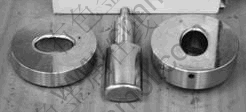
Fig.2 Blank holder, punch and die for elliptical cup drawing process
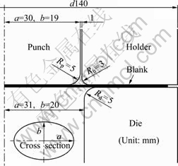
Fig.3 Schematic diagram of die size
2.2 Finite element simulation
The commercial software I-DEAS was used for pre-processing. Through grid segmenting and converting the established tools and blank, the incremental elastic-plastic large deformation three- dimensional finite element analysis program was entered for the elliptical cup drawing numerical analysis of forming process. The friction analysis between the blank and the tools used the Coulomb friction law, the grid meshing of the tools used the triangular element, and the grid meshing of the blank used the four-node quadrilateral shell elements (Belytschko-Tsay), suitable for nonlinear material models and widely used in the forming problems of large deformation and large rotation. The whole model used ULF as the processing reference coordinates, the solution criteria of the forming analysis were based on the Newton-Raphson iteration solution, and the convergence criteria were based on the relative residual displacement method. In the convergence error
analysis, ![]() was the changing amount of incremental displacement, where
was the changing amount of incremental displacement, where ![]() was
was
the changing amount of the displacement in iteration.
2.3 Material parameters
Blanks used in the experiments were provided by Tang Eng Stainless Steel Plant, a unit of Tang Eng Iron Works Co., Ltd. The material parameters and the mean thickness of the fracture surface obtained by the ASTM E646��93 standard tensile test are shown as follows: initial thickness of blank, t=0.8 mm; fractured thickness, tf=0.536 mm; yield stress, ��y=315 MPa; stress��strain
constitutive equation, ![]() ;
;
elastic modulus, E=2.1��105 MPa; Poisson ratio, ��=0.30.
3 Results and discussion
In elliptical cup drawing, the blank will withstand the drawing force when the punch moves downward, the friction force between blank and tools, and the hoop compression force generated by shrinkage of blank outer edge. Fig.4 shows the comparison between the numerical analysis of initial circular blanks with outer diameter of 106 mm and the relationship between punch load and stroke in the experiment. In the experiment, dry hard ester zinc powder lubricant was used in order to lower the dies damage and to improve the life span and benefit the finished stripping. The simulation was conducted in two groups with the friction coefficients set up at the parameters of ��=0.15 and ��=0.22, respectively. When the drawing started, the blanks moved to the middle and the outer diameter of the blanks was decreased, causing the contracted deformation in circumferential direction and the increase of work hardening of the blanks. Therefore, early in the forming, the punch load increased with the increase of punch stroke until the stroke was about 30.8 mm and the load punch reached the maximum of 81.9 kN. After the punch load reached the maximum, the blanks continued deformation with the increase of stroke. However, when the reducing rate of the blank flange area exceeded the process hardening rate of the blank, the punch load was reduced with the increase of the punch stroke, until the end of the drawing, the punch load
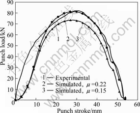
Fig.4 Relationship between punch load and stroke (outer diameter of 106 mm)
slowed down. The figure shows that the trend of the numerical analysis is consistent with the experimental punch load��stroke relationship.
When the punch came into contact with the blank, the thickness of the blank changed. When the stroke was about 30 mm in the middle stage of the forming process, because the drawing had not been completed yet, there were still a flange state at the blank edge and a change at the straight wall thickness of the blank due to the continued action of punch press. So, the even stretching reduced further the thickness of the blank. In addition, the blank in the part of the punch shoulder round corner, especially in the direction of the long axis of the punch, had significant changes in thickness. So, the region suffered the largest circumferential tensile stress; and with the increase of the punch stroke, the thickness in the direction of long axis became thin. In addition, the thickness of the blank in the direction of short axis of the punch got thinner with the increase of punch stroke; however, due to a larger radius of curvature in the geometric shape in the direction of the short axis, the circumferential tensile stress was less. Therefore, the changes of the thickness in the short axis compared to the long axis in the overall level are not significant. In the measurement of the work-piece entity, firstly, computer numerical control (CNC) wire cutting machine was used to cut a quarter of the part along the center line, then the thickness values of the forming work-piece were measured in the directions of long and short axes with cusp measurements micrometer, as shown in Fig.5.
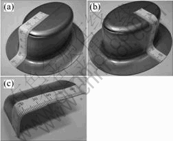
Fig.5 Measurement of blank thickness in directions of long (a) and short (b) axes of elliptical cup and measurement method (c)
In this study, the selected initial blanks were of 0.8 mm and 105 mm in thickness and diameter. In the rupture part, the rupture thickness (tf=0.536 mm) of the blank obtained from tensile test was used as the basis to predict the rupture in the elliptical cup drawing process of the metal sheet. In order to find limit forming ratio of the blanks, firstly, blank with 105 mm in outside diameter was used as a benchmark to conduct the experiment, and the experimental results showed that it can be formed in full shape. Then, the diameter of blank was increased with increment of 2.5 mm to conduct the second experiment, and the experimental result showed rupture. Finally, the diameter of the blank was reduced in increment of 0.5 mm for the third experiment, and the experiments were conducted in this way sequentially. The forming limit of sheet resistance was used to measure the rupture, and was the most important indicator of the main subject of plastic instability (rupture and wrinkling) restrictions and can be used for the blank to bear the instability before the maximum deformation. The extension ratio (drawing ratio, RDR), the limit drawing ratio (limit drawing ratio, RLDR) and the over-extended ratio (excessive drawing ratio, REDR), are defined as:
![]() (1)
(1)
![]() (2)
(2)
![]() (3)
(3)
where Cp stands for the circumference of elliptical column of punch; Ch stands for the circumference of initial blank without local neck shrink or rupture occurred; Ch, min stands for the circumference of the minimum initial blanks without local neck shrink or rupture occurred; and ![]() stands for the circumference of the initial blanks with local neck shrink or rupture occurred.
stands for the circumference of the initial blanks with local neck shrink or rupture occurred.
By comparison of the thickness change of the elliptical cup in the direction of long axis, when the outside diameter of the initial blank is less than 106 mm, from the numerical analysis or the experimental measurement results it can be seen that the least thickness of the elliptical cup is in the region of long axis arc radius, and both are larger than the thickness of rupture. This indicates that the blank can be shaped smoothly without neck shrink or rupture, as shown in Fig.6. However, when the initial outside diameter of the blank is greater than 106 mm, neck shrink (e.g. 106.5 mm) or rupture (e.g. 107.5 mm) occurs in the direction of the long axis of elliptical cup in the forming process, as shown in Fig.7 and Fig.8, respectively. As it has not yet reached the required drawing depth, the product remains in a state of the flange, the thickness is greater than the initial thickness of the blank, and with the increase of blank size, location of rupture tends to drop in the corresponding position.
By comparison of the thickness change of the elliptical cup on the direction of short axis, Fig.6 shows that the numerical analysis and experimental
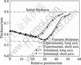
Fig.6 Distribution of thickness of blank with initial diameter of 106 mm (RDR=2.136) in directions of long and short axes of elliptical cup
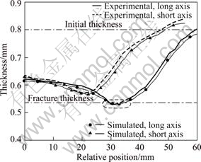
Fig.7 Distribution of thickness of blank with initial diameter of 106.5 mm (RLDR=2.146) in directions of long and short axes of elliptical cup
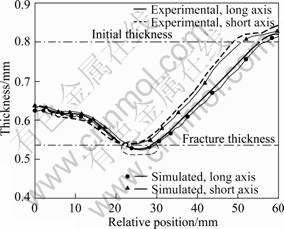
Fig.8 Distribution of thickness of blank with initial diameter of 107.5 mm (REDR=2.167) in directions of long and short axes of elliptical cup
results are still within a reasonable scope, but both are larger than the rupture thickness, and elliptical cup can be formed smoothly without neck shrink or rupture. Figs.7 and 8 show that the elliptical cup with neither neck shrink nor rupture will occur. But because it does not yet reach the drawing depth, so the finished product still remains in a state of flange, and the thickness is greater than the initial thickness of the blank. In the direction of short axis, in geometric shape the curvature radius is larger, and the circumferential tensile stress is less, so the thickness change in the direction of the short axis is smaller that in the long axis.
Fig.9 shows the work-pieces derived from the blanks in elliptical cup drawing at different forming ratios. Fig.9(a) shows that the blank with 106 mm in initial outside diameter can be shaped smoothly, and the limit drawing ratio obtained is 2.136. From Figs.9(b) and (c), and it can be found that obvious neck shrink or rupture occurs in the direction of long axis of elliptical cup, and the excessive drawing ratios are 2.146 and 2.167 respectively. Fig.10 shows the significant results of the blanks with initial diameters of 106 mm and 107.5 mm. As said above, despite the distribution of the blank thickness or the geometrical appearance of the elliptical cup, the results obtained by numerical analyses and experiments under different initial outside diameters of blanks are consistent.

Fig.9 Elliptic cup drawing products
Fig.11 shows that under the circumstances the arc radius of punch was fixed at Rp=5.0 mm; when the arc radius of die was increased from 3.0 mm to 9.0 mm, the limit drawing ratio will increase from 2.11 to 2.157. In contrast, in the fixed arc radius 5.0 mm, when the punch arc radius was increased from 3.0 mm to 9.0 mm, the limit drawing ratio will increase from 2.07 to 2.181, showing that the difficulty of forming around the die arc radius is larger than that of the punch arc radius.

Fig.10 Geometric appearance of simulated elliptical cup drawing products
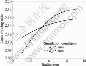
Fig.11 Changes of limit drawing ratio under condition of different die arc radius
4 Conclusions
1) The punch load will increase with the increase of punch stroke, and when it reaches the maximum, the blank continues deformation, but the punch load is gradually reduced until reaching the forming depth. Simulation analysis and experimental result are consistent in load distribution.
2) The minimum thickness concentrates in contact regions of the work-piece and long axis of the punch due to the fact that the long axis of the blanks faces the maximum tensile stress, while smaller radius of curvature of the region.
3) From the limit drawing ratio that is defined through the perimeters of the elliptical punch and the initial blank, it is known that the limit drawing ratio of elliptical cup drawing is 2.136.
4) As the punch arc radius and die arc radius increase, the limit drawing ratio will increase, and the difficulty of forming at around die arc radius values is larger than that of punch arc radius.
Acknowledgements
This work was funded by research projects (NSC97-2221-E-129-003) of the National Science Council, and the materials were provided by Tang Eng Stainless Steel Plant, a unit of the Tang Eng Iron Works Co., Ltd. We herewith express our appreciation.
References
[1] WIFI A S. Study on large strain elasto-plasticity and finite element analysis of deformation process [D]. Tokyo: University of Tokyo, 1978. (in Japanese)
[2] KORHONEN A S. Drawing force in deep drawing of cylindrical cup with flat-nosed punch [J]. Transactions of the ASME, Journal of Engineering for Industry, 1982, 104: 29-37.
[3] EAHSEL G, BARASH M, JOHNSON W. Rule based modeling for planning asixymmetrical deep-drawing [J]. Journal of Mech Working Tech, 1986, 14: 11-15.
[4] MARQUES B M J M, BAPTISTA R M S O. Theoretical and experimental analysis of axisymmetrical deep drawing [J]. Journal of Materials Processing Technology, 1990, 24: 53-63.
[5] YOSSIGON S, TIROSH J. The maximum drawing ratio in hydroforming processes [J]. Transactions of the ASME, Journal of Engineering for Industry, 1990, 112: 47-56.
[6] MAKINOUCHI A, SHIRATAKI Y, LIU S D, NAGAI Y. Generalization of tool-work contact conditions for elasto-plastic analysis of forming process [J]. Advanced Technology of Plasticity, 1990, 3: 1161-1166.
[7] SARAN M J, WAGONER R H. A consistent implicit formulation for nonlinear finite element modeling with contact and friction: Part I��Theory [J]. Transactions of the ASME, Journal of Engineering for Industry, 1991, 58: 499-506.
[8] SARAN M J, WAGONER R H. A consistent implicit formulation for nonlinear finite element modeling with contact and friction: Part II-Numerical verification and results [J]. Transactions of the ASME, Journal of Engineering for Industry, 1991, 58: 507-512.
[9] HUANG Y M, CHEN J W. Influence of the die arc on formability in the cylindrical cup-drawing process [J]. Journal of Materials Processing Technology, 1995, 55: 360-369.
[10] HUANG Y M, CHEN J W. Influence of the tool clearance in the cylindrical cup-drawing process [J]. Journal of Materials Processing Technology, 1995, 57: 4-13.
[11] HUANG Y M, CHEN J W. Influence of lubricant on limitation of formability of cylindrical cup-drawing process [J]. Journal of Materials Processing Technology, 1997, 63: 77-82.
[12] YANG L F, MORI K I, TSUJI H. Deformation behaviors of magnesium alloy AZ31 sheet in cold deep drawing [J]. Transactions of Nonferrous Metals Society of China, 2008, 18(1): 86-91.
[13] GAO En-zhi, LI Hong-wei, KOU Hong-chao, CHANG Hui, LI Jin-shan, ZHOU Lian. Influences of material parameters on deep drawing of thin-walled hemispheric surface part [J]. Transactions of Nonferrous Metals Society of China, 2009, 19(2): 433-437.
[14] HORTIG D, SCHMOECKEL D. Analysis of local loads on the draw die profile with regard to wear using the FEM and experimental investigations [J]. Journal of Materials Processing Technology, 2001, 115: 153-158.
[15] COLGAN M, MONAGHAN J. Deep drawing process: analysis and experiment [J]. Journal of Materials Processing Technology, 2003, 132: 35-41.
[16] ZAKY A M, NASSR A B, EL-SEBAIE M G. Optimum blank shape of cylindrical cups in deep drawing of anisotropic sheet metals [J]. Journal of Materials Processing Technology, 1998, 76: 203-211.
[17] HUH H, KIM S H, KIM S H. Process design for multi-stage elliptic cup drawing with the large aspect ratio [C]//European Congress on Computational Methods in Applied Sciences and Engineering. 2000: 11-14.
[18] KIM J B, YOON J W, YANG D Y, BARLAT F. Investigation into wrinkling behavior in the elliptical cup deep drawing process by finite element analysis using bifurcation-theory [J]. Journal of Materials Processing Technology, 2001, 111: 170-174.
����ֲĵęEԲ��������η���
������, ꑇ[��
ʥԼ����ѧ ��е��������������ϵ, ̨�� 25135
ժ Ҫ������Prandtl-Reuss��������� Hill�������оݣ�������ޱ������ۼ�updated Lagrangian formulation�ĸ�����ı����Ľڵ��˻���Ԫ��ż�ϵ����Ծ����У������ά����Ԫ�صķ���ģʽ��������ij������⡣�Բ��������������õ���Ƭ��������Ϊ��ֵ�������ƶ���̽����Բ��������ι����г���������̵Ĺ�ϵ��������ȷֲ������ι��̼����μ��ȡ�����ֵ������ʵ������֪������������ų�̵����Ӷ������غɴﵽ���ֵ����Ƭ���ų�̵����Ӷ��������Σ�ֱ���������Ϊֹ��������С��ȼ����ڹ�����ѹͷ����Ӵ�������������ʰ뾶�ȶ����С������Ƭ�ڳ��ᴦ�������������Ӧ����������Բѹͷ�ܳ����ʼ��Ƭ�ܳ�������ļ�������ȵ�֪������Բ�����εļ��������Ϊ2.136��
�ؼ��ʣ������о�; ����Ԫ; �EԲ���������; ���������
(Edited by YANG Hua)
Corresponding author: Yuung-min HUANG; Tel: +866-2-28013131-6724; E-mail: hyming@mail.sju.edu.tw
DOI: 10.1016/S1003-6326(11)60724-3
