
Trans. Nonferrous Met. Soc. China 29(2019) 692-700
Residual stress and welding distortion of Al/steel butt joint by arc-assisted laser welding-brazing
Chun-ling LI, Ding FAN, Xiao-quan YU, Jian-kang HUANG
State Key Laboratory of Advanced Processing and Recycling of Non-ferrous Metals, Lanzhou University of Technology, Lanzhou 730050, China
Received 31 March 2018; accepted 23 August 2018
Abstract:
The thermo-elastic-plastic finite element method (FEM) is used to simulate the thermo-mechanical behavior of Al/steel tungsten inert gas (TIG) arc-assisted laser welding-brazing (A-LWB) butt joint. The influence of material nonlinearity, geometrical nonlinearity and work hardening on the welding process is studied, and the differences in the welding temperature field, residual stress and welding distortion by A-LWB and by single laser welding-brazing (SLWB) are analyzed. The results show that the thermal cycle, residual stress distribution and welding distortion by the numerical simulation are in good agreement with the measured data by experiments, which verifies the effectiveness of FEM. Compared with the SLWB, A-LWB can make the high-temperature distribution zone of weld in width direction wider, decrease the transverse tensile stress in the weld and reduce the distribution range of longitudinal tensile stress. And the welding deformation also decreases to some extent.
Key words:
arc-assisted laser welding-brazing (A-LWB); Al/steel; finite element method (FEM); temperature field; residual stress; welding distortion;
1 Introduction
The Al/steel composite structure has excellent performances of dissimilar metals, such as high specific strength, excellent corrosion resistance, light weight, and low fuel consumption. Hence, it is widely used in the fields of aerospace, automobile manufacturing, shipbuilding, household appliances, and so on [1]. However, as for Al/steel welding, it is needed to control the thickness of intermetallic compounds (IMCs) layer within a reasonable range [2]. The IMCs are highly brittle and hard, which decreases the mechanical properties of joints because of their low critical stress intensity factor and high crack propagation rate [3,4]. The IMCs layer is closely related to the interfacial temperature during the welding process. If the interfacial reaction temperature can be predicted, the IMCs growth would be controlled [5].
The uneven temperature distribution would result in residual stress and welding distortion during the Al/steel welding process. The tensile residual stress around the weld is usually a negative factor, and it would result in the increase of the stress, fatigue fracture and brittle fracture [6]. The compressive residual stress has an adverse influence on the yield and buckling strength [7]. Furthermore, the thin plate is also prone to buckling distortion [8]. Therefore, it is beneficial for the design and structural parts safety to correctly evaluate the residual stress and welding distortion for the welding of Al to steel.
Some scholars have carried out much experiment and numerical analysis on the temperature field distribution, diffusion and residual stress prediction of dissimilar metals [5,9-13]. MENG et al [9] performed the calculation for the temperature distribution during the large spot laser assisted metal inert gas (MIG) welding-brazing and then revealed the auxiliary effect of the large spot laser. PARK and NA [10] simulated the temperature field of laser welding-brazing with wire feed between 304 stainless steel plug and 5052 aluminum alloy, then the brazing process was optimized and the stress field distribution of the joint was simulated [11]. AGUDO et al [12] studied the residual stress distribution of Al/steel butt CMT welding. It was shown that the residual stress distribution on the top surface was similar to that on the bottom surface. Likewise, HUANG et al [13] investigated the temperature field and residual stress distribution of Al/steel laser welding-brazing. The results indicated that the longitudinal residual stress on the steel plate was larger than that on the Al plate. The findings in the literatures mentioned above suggest that different materials or welding processes would cause different residual stress distributions.
A welding process named the arc-assisted laser welding-brazing (A-LWB) was introduced by the authors for joining Al to steel tailored blanks with butt joints [14]. Unlike the laser-arc hybrid welding, the energy coupling mechanism between laser and arc heat source was not considered in A-LWB. In the previous work, the interface layer structure and mechanical properties of the joint have been analyzed; however, the existing researches cannot reflect the residual stress and welding distortion production mechanisms of Al/steel by A-LWB. In this work, the thermo-elastic-plastic FEM is used to study the temperature field, residual stress and welding distortion of Al/steel butt joint in the A-LWB, and a comparison between A-LWB and single laser welding- brazing (SLWB) is performed.
2 Experimental
The experimental equipment consisted of the GS-TFL-10KCO2 laser and the HYLONG WSE-250 TIG welder. The materials were ST04Z galvanized steel and 5A06 aluminum alloy, and their sizes were 150 mm�� 50 mm �� 1 mm and 150 mm �� 50 mm �� 2 mm, respectively. The laser vertically heated the base metal surface and deviated about 2 mm from the edge of aluminum alloy. In addition, the TIG arc tilted toward the welding direction. During the welding process, the plates were restrained by the fixture, and the welding schematic is shown in Fig. 1. During the A-LWB process, the welding parameters were as follows. The laser power was 1200 W, the welding speed was 10 mm/s, the defocus amount was 0, the arc current was 15 A, the arc voltage was 14 V, and the center distance of heat source was 15 mm. The SLWB had the same heat input as A-LWB.

Fig. 1 Schematic view of arc-assisted laser welding-brazing
The weld joints are shown in Fig. 2. It can be seen that the wetting and spreading of liquid metal on the back of the galvanized steel is good.
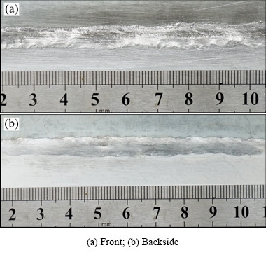
Fig. 2 Weld joint
The welding residual stress of A-LWB was measured by the MSF/PSF-3M X-ray stress analyzer. The contour of the plate was measured by the Global Image 9128 coordinate measuring machine (CMM), and the Cero 2.0 software was used to characterize the data point cloud measured by CMM.
3 Finite element modeling
Based on the finite element software ANSYS, the sequential coupling method was used to simulate the temperature field and welding stress. The finite element modeling is shown in Fig. 3. The welding zone was covered by the fine grids, and the grid size gradually increased with the increase of distance between the heat source and the base metal. SOLID70 was used during the thermal analysis, and it was converted into the structural element SOLID 45 in the stress calculation.

Fig. 3 Finite element model and boundary condition (Unit: mm)
3.1 Heat source model
The law of conservation of energy and Fourier��s law are used for thermal analysis, the flow of the molten pool is ignored, and the thermal conductivity �� is isotropic. Then, the transient heat conduction equation is shown as follows:
 (1)
(1)
where T is the temperature, �� is the thermal conductivity, �� is the material density, and c is the specific heat capacity. During the welding process, the aluminum was melted, the steel would not be melted, and then the melted material spread on the surface of steel with the help of TIG arc. During the brazing process, the liquid metal flowed through the gaps at a high temperature to wet and spread, so it could be regarded as a heat source [15]. According to the heat transfer characteristics of welding process (heat conduction) and the geometrical characteristics of weld, the energy of the laser beam is divided into two parts. One part is used as the Gaussian surface heat source to melt the aluminum alloy. The other part is used as the Rotary-Gauss body heat source [16] for the filling, wetting and spreading of liquid metals in the material interior.
The equation of heat flow density of Gaussian surface heat source is
 (2)
(2)
where qs is the heat flux density, R is the effective radius of the laser beam, ��1 is the thermal efficiency coefficient, Q1 is the heat input power of the Gaussian surface heat source, Q1=kQ and k is the energy ratio.
The heat flux density of Rotary-Gauss body heat source can be written as
 (3)
(3)
where qv is the heat flux density, H is the depth of the heat source, ��2 is the thermal efficiency coefficient, and Q2 is the heat input power of the Rotary-Gauss body heat source. Moreover, Q2=Q-Q1=(1-k)Q, and the value of k is 0.7 by analysis and contrast.
TIG heat source power is small, and it is regarded as the double-ellipse planar heat source. The angle between the TIG arc axis and welding direction is assumed as ��, which is shown in Fig. 1. The double-ellipse planar heat source model after conversion is as follows:
 (4)
(4)
 (5)
(5)
where Qf and Qr are the powers of the front part and rear part of double-elliptic heat source, respectively. Qf+Qr=��3P1, and P1=UI. P1 is the TIG welding power, U is the arc voltage, I is the welding current, and ��3 is the thermal efficiency of TIG welding. a3, b3 and b4 are the shape parameters of the double-elliptic heat source.
The total convection heat transfer coefficient hc represents the heat radiation and convection. The heat source moves forward on the top surface of the plates, and the temperature T on the surface of the plates changes with the time and space. On the top surface of the plates, the boundary condition is
 (6)
(6)
where n is the normal direction of the outer surface, and T0 is the initial temperature set to be 20 ��C.
On the bottom surface and the surrounding surface of the plate, there is
 (7)
(7)
The equivalent specific heat method is used for solid-liquid transition in 5A06 aluminum alloy. Thermal properties of the two materials are set as a function of temperature [9], as shown in Fig. 4.
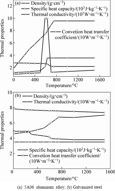
Fig. 4 Thermal properties of materials
3.2 Mechanical analysis
The creep behavior of the material is ignored in the stress calculation, and the total strain increment d��ij mainly consists of elastic strain increment  , plastic strain increment
  and thermal strain increment
  :
:
 (8)
(8)
The elastic strain increment is calculated by the Hooke��s law for the isotropic material, and thus depending on the elastic modulus and Poisson ratio. The thermal strain increment could be calculated by the thermal expansion coefficient of the material, and the plastic strain increment satisfies the von Misses yield criterion. The stress-strain relationship of the material is characterized by a bilinear isotropic hardening model [17]. The yield strength of materials at a high temperature is estimated by an engineering method [18]. Figure 5 shows the change of mechanical properties of materials with the temperature.
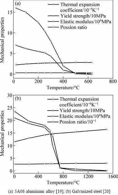
Fig. 5 Mechanical properties of materials
In order to accurately predict the thin plate deformation, the large deformation theory is preferentially used in the structural stress calculation [20], and the stress distribution and distortion are greatly affected by the restraint of fixtures [21-25]. In this study, the degrees of freedom where the plate contacts with the fixture (rectangular region in Fig. 3) are restrained during the welding process. Then, on cooling, the restraints are removed (t=100 s). Simultaneously, in order to avoid the rigid movement or torsion in the simulation process, the degrees of freedom of points 1, 2 and 3 on the plate are restrained (the arrows shown in Fig. 3).
4 Simulation results and discussion
4.1 Temperature field
Figure 6 shows the temperature field distribution on the top surface in welding process (t=12 s). It can be seen that the high-temperature range in the aluminum alloy is larger than that in the steel. The reason is that different thicknesses and different heat conductivity coefficients for different materials would result in asymmetrical temperature field along the weld, and the heat flux rapidly transfers to aluminum alloy, thus forming a large range of high-temperature distribution. The high- temperature range in the width by A-LWB is larger than that by SLWB. However, the temperature in SLWB obviously rises, which would result in significant increase of IMCs thickness, thus making the mechanical properties of joints deteriorate.
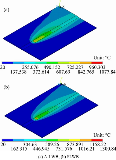
Fig. 6 Temperature distribution at t=12 s
The thermal cycle in the brazing interface has a great influence on the wetting and spreading of liquid metal as well as the formation of IMCs [9]. Figure 7 shows the thermal cycles at the brazing interface (y=0, 0.5, 1) at z=75 mm of joint. In A-LWB, each point experiences two thermal cycles, and the curve displays the double peaks. Compared with SLWB, the high- temperature zone enlarges in the interface, which prolongs the presence of liquid metal and improves its wetting and spreading on steel surface. Hence, the auxiliary arc is beneficial for the wetting and spreading, thus improving the joints quality.
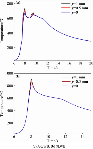
Fig. 7 Thermal cycles at brazing interface

Fig. 8 Cross-section of A-LWB obtained by simulation and experiment
Figure 8 shows the cross-section morphologies of A-LWB joint by FEM simulation and by the experiment, respectively. The temperature field above 625 ��C (the liquidus temperature of 5A06 aluminum alloy) is regarded as a melting zone, and the gray area represents the melting zone. Obviously, the simulated result generally agrees with the experiment result.
Then, the comparison for the thermal cycles of Point D and Point E on the top surface of the steel in A-LWB joint is carried out, as shown in Fig. 9. The distribution of the simulated results agrees well with that of the experiment results except some local difference in high-temperature zone.
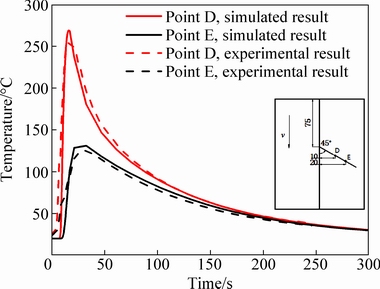
Fig. 9 Thermal cycles of A-LWB obtained by simulation and experiment
It is the prerequisite for the suitable welding distortion and residual stress that melting zone size is accurately predicted [26]. By the comparison of melting zone morphology and thermal cycles between the simulation and the experiment, it can be clearly seen that the heat source model and model parameters are reasonable, and they can accurately reflect the thermal cycle process of A-LWB. Therefore, the temperature field simulation results can be used for the subsequent stress field.
4.2 Welding residual stress

Fig. 10 Contours of transverse residual stress (t=300 s)
The welding stresses are simulated in the A-LWB and SLWB processes, respectively. Figure 10 shows the distribution contours of the transverse residual stress on the middle cross-section of the welds. Obviously, the transverse residual stress distribution is asymmetric, and the stress distribution in the SLWB joint is similar to that in the A-LWB joint. The maximum magnitude appears on brazing weld near the steel side on the top and bottom surfaces of the joint. Compared with the A-LWB, the tensile stress magnitude of joint by SLWB is higher. This is because the higher temperature in SLWB joint leads to the increase of the stress.
Figure 11 shows the distribution contours of the longitudinal residual stress on the middle cross-section of the welds. Obviously, the longitudinal residual stress distribution is also asymmetric. Compared with transverse stress, the values of longitudinal residual stress is much larger. The high tensile stress concentrates on the weld and heat-affected zone (HAZ) of aluminum alloy, and higher than the yield strength of aluminum alloy for the influence of work hardening. In order to meet the strain coordination conditions, the longitudinal stress should be the compressive stress on the base metal. In this experiment, the aluminum alloy melts and spreads after being heated, the yield strength and elastic modulus decrease to zero, and the thermal expansion of aluminum alloy is restrained by the surrounding cold steel which does not melt. During the cooling, the steel restrains the shrinkage in the weld and HAZ as an internal binding force, and thus the tensile residual stress appears at the weld. By comparison, the difference in the peak tensile stresses of the two welding processes is small. However, the distribution range of high tensile stress of SLWB is wider than that of A-LWB on the weld.
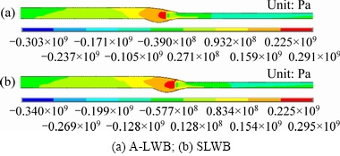
Fig. 11 Contours of longitudinal residual stress (t=300 s)
Figure 12 shows the comparison for the distributions of transverse residual stress by FEM simulation and by experiment in A-LWB joint on the top surface. The transverse stress on the steel side is larger than that on the aluminum alloy side. On the aluminum alloy plate, a peak of transverse stress appears about 10 mm away from the welded metal boundary, which is caused by the larger temperature gradient between the melting zone and the aluminum alloy base metal. Near the interface, the residual stress is unstable and has the saltation, and the reason is that aluminum has a much larger thermal expansion coefficient than steel. With the decrease of temperature, the cooling rates of aluminum alloy and steel are different, similar to the stress distributions of dissimilar steels [27]. This situation of residual stress distribution also suggests that the fracture easily occurs in the interface, and this also means that the fracture is more likely to occur in SLWB joint due to much serious stress concentration. For the transverse stress, the simulated values generally agree well with the measured values, but the two are different at the center of the weld and on the aluminum alloy substrate. The reason is that there exists the initial residual stress before welding, and the stress far away from the weld is less affected during the welding process [28].
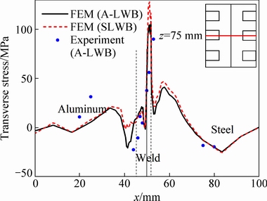
Fig. 12 Transverse residual stress on middle cross-section of top surface
Figure 13 shows the comparison for the distribution of longitudinal residual stress by FEM simulation and by experiment in A-LWB joint on the top surface. Because the range of high-temperature of aluminum alloy is larger than that of steel, the longitudinal tensile stress distribution in the former is far wider than that in the latter. By comparison, the simulated longitudinal stress distribution generally matches the measured data. However, there are still some differences between them due to the initial stress. The distribution of longitudinal residual stress on the top surface by SLWB is similar to that by A-LWB.
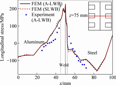
Fig. 13 Longitudinal residual stress on middle cross-section of top surface
4.3 Welding distortion
Figure 14 shows the contours of deflection distribution calculated by FEM. The deformations of two welding processes both have a convex-concave shape, but the deformation magnitude of SLWB is a little larger than that of A-LWB.
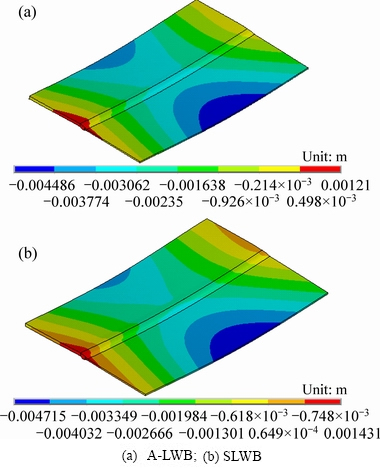
Fig. 14 Contours of deflection distributions
Figure 15 shows the comparison of the deflections (displacement in y direction) by SLWB and by A-LWB as well as the measured displacement distribution by A-LWB. It can be obviously seen that the displacements on aluminum alloy and steel are asymmetric, and the deflection on the steel is larger than that on the aluminum alloy. The reason is that the thickness of steel plate is only 1 mm, thinner than that of the aluminum alloy plate, so it is more prone to deformation. The displacement distributions on aluminum alloy side by SLWB and by A-LWB are basically the same, but the deformation of SLWB is slightly larger than that of A-LWB on steel side and at z=145 mm. It can be seen that the deformation distributions of A-LWB agree well with the corresponding measured values in shape, but there are some differences in magnitude between them. In order to improve the deformation prediction accuracy, the external restraint must be carefully set in the FEM [26]. In general, the large deformation theory can accurately predict the welding deformation in the FEM for thermo-mechanical behavior of aluminum alloy to steel thin plate joints.
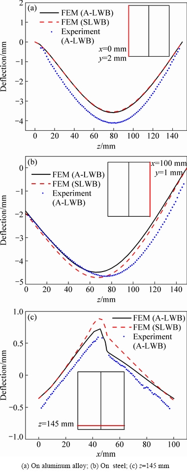
Fig. 15 Deflection distributions
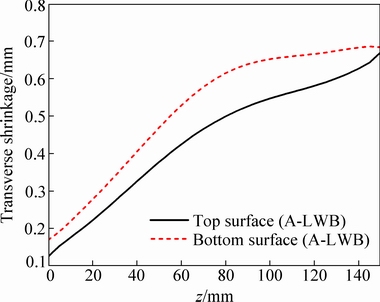
Fig. 16 Transverse shrinkage in A-LWB joint
The mechanisms of thin plate deformation have been discussed in Refs. [26,29,30]. The heat input in the two welding processes is relatively large. After the aluminum alloy melts, most of the liquid metal spreads on the top side of the steel plate, and a small part spreads on the bottom side. During the cooling, the longitudinal shrinkage force on the top of weld is obviously larger than that on the bottom. Thus, a concave bending deformation occurs in the longitudinal direction, and the convex bending deformation occurs in the transverse direction in order to coordinate the overall deformation. So, there appears a convex-concave shape in the joint. Figure 16 shows the transverse shrinkage on top and bottom surfaces of A-LWB. It can be found that the transverse shrinkage on the top surface of the plate is smaller than that on the bottom surface. Therefore, the plate has a convex deformation along the width direction. According to the deformation coordination principle of the thin plate, if the convex deformation in the width direction appears, the corresponding concave deformation would appear in the longitudinal direction.
It is found by the simulation and experiment that the thin plate welding distortion is closely related to different layouts of fixtures and restraint ways [22-25]. Different restraints have different plastic deformations on the weld and the HAZ, thus resulting in different residual stresses and distortions of the plate. The external restraint could mitigate the deformation to a certain extent [26]. In future work, in order to limit the residual stress and welding distortion of the aluminum alloy to steel welding, the heat input should be controlled under the effective connection between aluminum alloy and steel, and then the fixtures should be reasonably arranged. For example, the configuration and the number of clamps should be changed, because they have different influence on the finial distortion of plate.
5 Conclusions
(1) The comparison between simulated results and experimental results show that the numerical results by the thermo-elastic�Cplastic FEM could accurately describe the temperature field, residual stress distribution and deformation characteristics of the plate, thus verifying the model validity.
(2) It is found by comparing the simulation results of SLWB and A-LWB that the high-temperature area zone caused by the assisted arc becomes wider, which benefits the wetting and spreading of liquid metal. The transverse tensile residual stress on the weld by A-LWB decreases. Likewise, the distribution of longitudinal tensile residual stress on the weld in the A-LWB joint reduces. Thus, the welding deformation becomes small.
(3) The temperature field, stress distribution and welding distortion on the aluminum alloy and steel are asymmetric, and the high-temperature range of aluminum alloy is larger than that of steel. Thus, the tensile stress distribution is larger than the steel, but the deflection on the steel is larger than that on the aluminum alloy.
(4) Because the geometrical nonlinearity is serious in thin plate deformation, the simulation results of the welding distortion in Al/steel butt joint by large deformation theory are in good agreement with the experimental results.
References
[1] WANG Peng-fei, CHEN Xi-zhang, PAN Qiu-hong, MADIGAN B, LONG Jiang-qi. Laser welding dissimilar materials of aluminum to steel: An overview [J]. International Journal of Advanced Manufacturing Technology, 2016, 87: 3081-3090.
[2] SIERRA G, PEYRE P, DESCHAUX-BEAUME F, STUART D, FRAS G. Steel to aluminium key-hole laser welding [J]. Materials Science and Engineering A, 2007, 447: 197-208.
[3] YANG Jin, LI Yu-long, ZHANG Hua.Microstructure and mechanical properties of pulsed laser welded Al/steel dissimilar joint [J]. Transactions of Nonferrous Metals Society of China, 2016, 26: 994-1002.
[4] TRAN V X, PAN J. Fatigue behavior of dissimilar spot friction welds in lap-shear and cross-tension specimens of aluminum and steel sheets [J]. International Journal of Fatigue, 2010, 32: 1167-1179.
[5] RATTANA B, TAISEI Y, YUKIO M, YOSHIHARU M. Suppression of intermetallic reaction layer formation by controlling heat flow in dissimilar joining of steel and aluminum alloy [J]. Materials Science and Engineering A, 2007, 467: 108-113.
[6] ZENG Zhi, LI Xun-bo, MIAO Yu-gang, WU Gang, ZHAO Zi-jin. Numerical and experiment analysis of residual stress on magnesium alloy and steel butt joint by hybrid laser-TIG welding [J]. Computational Materials Science, 2011, 50: 1763-1769.
[7] AHMADZADEH M, FARSHI B, SALIMI H R, HOSEINI FARD A. Residual stresses due to gas arc welding of aluminum alloy joints by numerical simulations [J]. International Journal of Material Forming, 2013, 6: 233-247.
[8] HE Ya-zhang, WANG Dong-po, WANG Ying, ZHANG Hai. Correction of buckling distortion by ultrasonic shot peening treatment for 5A06 aluminum alloy welded structure [J]. Transactions of Nonferrous Metals Society of China, 2016, 26: 1531-1537.
[9] MENG Xiang-meng, QIN Guo-liang, SU Yu-hu, FU Bang-long, JI Yang. Numerical simulation of large spot laser+MIG arc brazing- fusion welding of Al alloy to galvanized steel [J]. Journal of Materials Processing Technology, 2015, 222: 307-314.
[10] PARK J S, NA S J. Heat transfer in a stud-to-plate laser braze considering filler metal movement: A thermal computation model with the aid of a high-speed motion analyzer helps the development of a stainless steel to aluminum laser brazing process [J]. Welding Journal, 1998, 77: 155s-163s.
[11] PARK J S, NA S J. A Study on the numerical analysis of thermomechanical behaviour in a stud-to-plate laser braze joint [J]. Proceedings of the Institution of Mechanical Engineers. Part C: Journal of Mechanical Engineering Science, 1999, 213: 763-774.
[12] AGUDO L, WEBER S, PINTO H, ARENHOLZ E, WAGNER J, HACKL H, BRUCKNER J, PYZALLA A. Study of microstructure and residual stresses in dissimilar Al/Steels welds produced by cold metal transfer [J]. Materials Science Forum, 2008, 571-572: 347-353.
[13] HUANG Jian-kang, YANG Mao-hong, LIU Jian, FAN Ding, YU Shu-rong. Residual stress field analysis of Al/steel butt joint using laser welding-brazing [J]. Materials Science and Technology, 2017, 33: 2053-2063.
[14] FAN Ding, WANG Bin, LI Chun-ling,HUANG Jian-kang, YU Shu-rong. Method of fusion-brazed butt joint between aluminum alloy and galvanized steel by arc-assisted laser [J]. Transactions of the China Welding Institution, 2015, 36: 15-18, 58.
[15] FENG Xiao-song, CHEN Yan-bin, LI Li-qun. Temperature filed simulation of laser brazing for galvanized steel sheets [J]. Acta Metallurgica Sinica, 2006, 42: 882-886.
[16] WU Su, ZHAO Hai-yan, WANG Yu, ZHANG Xiao-hong. A new heat source model in numerical simulation of high energy beam welding [J]. Transactions of the China Welding Institution, 2004, 25: 91-94.
[17] LIANG Wei, MURAKAWA H, DENG De-an. Investigation of welding residual stress distribution in a thick-plate joint with an emphasis on the features near weld end-start [J]. Materials and Design, 2015, 67: 303-312.
[18] ZHU X K, CHAO Y J. Effects of temperature-dependent material properties on welding [J]. Computers and Structures, 2002, 80: 967-976.
[19] SHI Jun-wei, HU Min-ying. Finite element numerical simulation of temperature field in deep penetration laser welding for aluminum alloys [J]. Hot Working Technology, 2009, 38: 120-122.
[20] DENG De-an, MURAKAWA H. Prediction of welding distortion and residual stress in a thin plate butt-welded joint [J]. Computational Materials Science, 2008, 43: 353-365.
[21] LIU C, ZHANG J X. Investigation of external restraining force effects on welding residual stresses using three-dimensional thermal elastic-plastic multi-body coupling finite element model [J]. Proceedings of the Institution of Mechanical Engineers. Part B: Engineering Manufacture, 2009, 223: 1591-1600.
[22] ZHANG Jian-qiang, ZHAO Hai-yan, LU An-li, LUO Chuan-hong, GUO Jia-lin, ZHANG Guo-dong. Effects of clamps on welding distortion in thin aluminum alloy plate [J]. Rare Metal Materials and Engineering, 2009, 38: 165-169.
[23] WANG Xue-dong��HE En-guang, CHEN Li. Influence of constraint on welding deformation of T joint welded by dual-beam laser [J]. Transactions of the China Welding Institution, 2016, 37: 101-105.
[24] ZHANG Zeng-lei, SHI Qing-yu, YAN Dong-yang, CAI Zhi-peng. Establishment and application of fixture constraint models in finite element analysis of welding process [J]. Acta Metallurgica Sinica, 2010, 46: 189-194.
[25] GUO Yu-quan, WU Dong-jiang, MA Guang-yi YANG Yi-bin, TONG Yu, GUO Dong-ming. Influence of fixture restraint distance on pulsed laser welding distortion of Hastelloy C-276 thin sheet [J]. Optics and Precision Engineering, 2012, 20: 2465-2471.
[26] DENG De-an, LIU Xiao-zhan, HE Jing, LIANG Wei. Investigating the influence of external restraint on welding distortion in thin-plate bead-on joint by means of numerical simulation and experiment [J]. The International Journal of Advanced Manufacturing Technology, 2016, 82: 1049-1062.
[27] BANG H S, BANG H S, KIM Y C,OH I H, SUNG B S. Mechanical and microstructural characteristics of the dissimilar materials butt joints by hybrid CO2 laser-gas metal arc welding [J]. Journal of Laser Applications, 2011, 23: 012002-012008.
[28] DENGDA, KIYOSHIMA S. Numerical simulation of residual stresses induced by laser beam welding in a SUS316 stainless steel pipe with considering initial residual stress influences [J]. Nuclear Engineering Design, 2010, 240: 688-696.
[29] MANURUNG Y H P, SULAIMAN M S, ABAS S K, THAM G, HARUMAN E. Investigation on welding distortion of combined butt and T-joints with 9-mm thickness using FEM and experiment [J]. The International Journal of Advanced Manufacturing Technology, 2015, 77: 775-782.
[30] WANG Jiang-chao, YIN Xian-qing, MURAKAWA H. Experimental and computational analysis of residual buckling distortion of bead-on-plate welded joint [J]. Journal of Materials Processing Technology, 2013, 213: 1447-1458.
��/�ֵ绡����������ǥ���Ӳ���Ӧ�������ӱ���
��ᣬ�� ��������ȫ���ƽ���
����������ѧ ʡ��������ɫ�����Ƚ��ӹ��������ù����ص�ʵ���ң����� 730050
ժ Ҫ��������-��-��������Ԫ������/�����ֽ����ټ��������屣��(TIG)����������Խ���ǥ����(A-LWB)���̽�����ֵģ�⣬���Dz��Ϸ����ԡ����η����Ժͼӹ�Ӳ����Ӱ�죬�뵥���⺸��(SLWB)�������¶ȳ�������Ӧ���ͺ�����ν��жԱȡ������������ֵ����õ�����ѭ��������Ӧ���ͺ��ӱ������������ǺϽϺã���֤����Ԫ���㷽������Ч�ԡ���SLWB��ȣ�A-LWBʹ�ú�������ϵĸ��·ֲ���Χ��������ͺ��촦�����ĺ�����Ӧ������С���촦������Ӧ���ķֲ���Χ����һ���̶��ϼ�С������Ρ�
�ؼ��ʣ��绡����������ǥ������/�֣�����Ԫ�����¶ȳ�������Ӧ�������ӱ���
(Edited by Bing YANG)
Foundation item: Project (51465031) supported by the National Natural Science Foundation of China; Project (17JR5RA126) supported by the Natural Science Foundation of Gansu Province, China
Corresponding author: Ding FAN; Tel:+86-931-2973563; E-mail: fand@lut.cn
DOI: 10.1016/S1003-6326(19)64979-4
Abstract: The thermo-elastic-plastic finite element method (FEM) is used to simulate the thermo-mechanical behavior of Al/steel tungsten inert gas (TIG) arc-assisted laser welding-brazing (A-LWB) butt joint. The influence of material nonlinearity, geometrical nonlinearity and work hardening on the welding process is studied, and the differences in the welding temperature field, residual stress and welding distortion by A-LWB and by single laser welding-brazing (SLWB) are analyzed. The results show that the thermal cycle, residual stress distribution and welding distortion by the numerical simulation are in good agreement with the measured data by experiments, which verifies the effectiveness of FEM. Compared with the SLWB, A-LWB can make the high-temperature distribution zone of weld in width direction wider, decrease the transverse tensile stress in the weld and reduce the distribution range of longitudinal tensile stress. And the welding deformation also decreases to some extent.
