

Melting behavior of magnesium alloy chips in thixomolding process
CUI Xiao-peng(������)1, LIU Hai-feng(������)2, LIU Yong-bing(���±�)3
1. Institute of Materials Science and Engineering, Changchun University of Technology, Changchun 130012, China;
2. R&D Centre, Foundry Corporation, FAW Group Corporation, Changchun 130062, China;
3. Key Laboratory of Automobile Material, Ministry of Education, Jilin University, Changchun 130025, China
Received 15 July 2007; accepted 10 September 2007
Abstract:
The samples were fabricated by 220 t thixomolded machine made by Japan Steel Works. The microstructure from the AZ91D magnesium alloy chips to the thixomolded products was investigated. Melting behavior of the chips in thixomolding process was analyzed. The evolution processing of solid phase morphology was studied, and evolution model was put forward. The results show that microstructures in outer zone of a chip and the inner zone are obviously different, and the severe distortion takes place in the brim of the chip, where the grains are observed to be bent, distorted, even broken. The severe plastic deformation region is firstly molten, then segregation area in the inner of the chip continues to melt. The liquid phase in solid phase does not formed by liquid entrapped during shearing process, but primarily induced by internal composition segregation.
Key words:
AZ91D magnesium alloy; thixomolding; chips; melting behavior;
1 Introduction
Magnesium alloy is the lightest metal that can be used as structural material at present. As environmentally friendly metal materials, magnesium alloys can be applied in many fields, such as the automotive industries, aeronautical industries and ��3C�� (Computer, Communication, Consumption Electronics Products) industries[1-2]. The manufacturing processes for magnesium alloys components include die casting, squeeze casting, semi-solid forming (SSF), etc. SSF has so many advantages, and has been called the most promising materials processing technique in the 21st century[3]. As a revolutionary semi-solid forming process for magnesium alloys, thixomolding can result in a product with few defects, superior dimensional accuracy, better surface quality, higher mechanical properties[4]. Only magnesium alloys can be formed by thixomolding method on an industrial scale[5]. At present, the raw materials for thixomolding mainly include AZ91D, AM50B, AM60A in China. Because there are too little technique data on thixomolding processing, many novel magnesium alloys can not be used, which restrict thixomolding to be applied widely[6-7]. In the previous study, it is usually considered that strongly stirring induces liquid phase to be entrapped into solid phase in semi-solid forming[8-9]. In this research, melting behavior of the raw materials for thixomolding were studied. Forming mechanism and evolution of the solid phase in microstructure were discussed. A melting model was also brought up to analyze the microstructure and explain microstructure transition. The results obtained in this paper will play an guidance role for thixomolding of magnesium alloy in the further industrial application.
2 Experimental
2.1 Materials
According to the requirement to thixomolding materials and the characteristic of this forming method, AZ91D, the most popular magnesium alloy in the present industrial field, was selected. The chemical composition is 8.3% Al, 0.54% Zn, 0.14% Mn, 0.011% Si, Fe, Cu and Ni below 0.01%, and Mg balance, which were determined by the ICP spectral analyzer.
2.2 Process parameters
The thixomolded machine used for this experiment was JLM220-MG made by Japan Steel Works (JSW). The mobile phone shell and its gating system are shown in Fig.1.
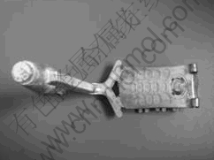
Fig.1 Thixomolding structure and gating system of mobile phone housing in this experiment
The mobile phone house has complicated structure and thin wall of approximately 1mm. It was a prerequisite of parameters adjustment that the mobile phone shells must have complete appearance and good surface quality. In this experiment, the adjusted process conditions included barrel temperature, injection velocity, screw rotate rate and mold temperature. The main process parameters were as follows: the barrel temperature 580-610 ��; injection velocity 1.0-2.6 m/s; mold temperature was set between 180-230 ��; and two screw rotate rate, viz. 105 and 168 r/min, were selected.
2.3 Microstructure analysis
The research samples were cut from the same position in each of mobile phone housings. Surface preparation consisted of polishing with Al2O3 powder suspension, followed by etching in a 2% solution of nitric acid in ethanol. The examination of the samples was performed using an optical microscope and a scanning electron microscope (JSM-5310) with an energy dispersive X-ray spectrometer (EDX). The volume fraction and morphology of the solid phase were evaluated by analysis software, which was developed on MATLAB 7.0 platform in this study[10].
3 Results
3.1 Microstructure of raw materials for thixomolding
The chips, raw material for thixomolding used in this research, were cut from the commercial magnesium alloy ingots by a special cutting tool. The spatial morphology of chip was composed of distorted column along its long direction, and its dimension was about 1 mm��1 mm�� 5 mm. The chip microstructure was shown in Fig.2. The light color region in the grain was ��-Mg solid solution, and there were some precipitated phase, Mg17Al12 (�� phase), distributed in the ��-Mg solid solution at random. The region at darker color located at the grain boundaries was the eutectic phase which consisted of ��-Mg and Mg17Al12 (�� phase).
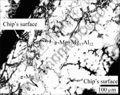
Fig.2 Microstructure of magnesium alloy chip
The microstructures in outer zone of chip and the inner zone were obviously different. Because of cutting force in the chip fabrication process, the distortion took place in the chip��s brim. The bended, distorted, and even broken grains could be observed in the outer zone of chip and the grain size is smaller than that of the inner zone. The outer zone of chip was defined as severe plastic deformation region, which occupied 1/3-1/4 along the width direction. Compared with the outer zone, there was little effect of cutting force on the microstructure of inner zone, which was defined as normal region.
3.2 Microstructure of thixomolding AZ91D magnesium alloy
The representative microstructure of thixomolding AZ91D magnesium alloy is shown in Fig.3. Different from the microstructure of HPDC, a number of solid phases, near to spheroid scattered in the fine matrix, can be observed in the semi-solid microstructure. There were two forms of solid phase particles, one was coarse solid phase (Fig.3 ��), and some contained liquid phase in interior, the other is fine solid phase (Fig.3 ��)[11]. The fine matrix consists of ��-Mg eutectic solid solution and inter-metallic �� phase surrounding the grain boundary.
3.3 Semi-solid microstructure
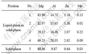
The analysis of semi-solid microstructure by EPMA is shown in Fig.4. The uneven distribution of Al and Mg can be found in the EPMA results. The composition of solid phase and liquid phase within solid phase was detected by WDS, and the analysis results are listed in Table 1. From Table 1, the chemical composition of the solid phase was basically the same as that of AZ91D alloy, and there were great difference in chemical composition between solid phase and liquid phase in solid phase. Al content in the liquid phase was much higher than that in AZ91D.
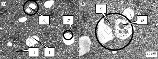
Fig.3 Microstructures of thixomolding AZ91D magnesium alloy

Fig.4 BSE image and map analysis of solid phase and liquid phase by EPMA
Table 1 Analysis results of some points in semi-solid microstructure by WDS (mass fraction, %)
4 Discussion
4.1 Formation and evolution of solid phase
It is a particular characteristic of semi-solid forming structure that the dendrite converted into spheroid grains. In the previous study, it was generally thought that the formation of the non-dendrite microstructure depended on the intense agitation during semi-solid processing[8].
In the present study, the inner microstructure of solid phase was investigated in details. After deep-etching, the dendrite and recrystallization structure can be observed in the solid phase (Fig.5). The appearance of dendrite showed that the dendrite in solid phase was not completely broken by agitation in semi-solid processing.
In Fig.5(b), the nearly separate two solid phase could be observed, and a liquid phase and some connection existed in the middle of two solid phase. A variety of dimension of liquid phase can also be found in the two solid phases.
During thixomolding process, it would spend about 40 s from the chips entering the barrel to finishing molding. In such short time, it is impossible that the whole chip could be molten entirely. It was supposed that solid phase in the thixomolding microstructure was basically formed by unmelted magnesium alloy chips.
Because the chips for thixomolding were cut from commercial magnesium alloy casting ingot, there was not only macrosegregation but also microsegregation during the ingot solidification. In other words, the microstructure of the chips was composition inhomogeneous.
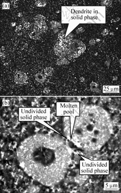
Fig.5 Microstructures of solid phase: (a) Dendrite microstructure; (b) Melting break solid phase
Due to chemical composition variety, the different micro-region of chip has different melting point. The melting point of region with higher Al content is lower than that with less Al content. When the temperature was increased, the region with higher Al content firstly began to melt, and some small melting pools were formed. As the temperature increased continuously, more and more pools were formed and several pools combined to one big pool.
In the previous research, it is generally believed that the liquid can be entrapped into solid phase during the strong agitation and formed the ��pool�� [8-9]. If it were true, there should not be great difference on the contents between the liquid phase that ��entrapped into�� the solid phase and the molten AZ91D. In this study, Al content in liquid phase that ��entrapped into�� the solid phase was more than that of the molten AZ91D. It can be affirmed that the liquid phase in the solid phase is formed by microsegregation, not by liquid entrapped.
In summary, there are two types of solid phase in thixomolded microstructure, that is, the unmelted chips and the molten solid phase. The former is main part of the solid phase (Fig.3(a)-��), and most of the latter was obtained under the shearing stress (Fig.3(a)-��). At low processing temperature, solidification microstructure was fine and small, and the solid phase composed of the broken dendrite was small in dimension. It was concluded that all of the bigger solid phase particles were unmelted chips.
4.2 Evolution model of solid phase
During the semi-solid process, formation and evolution of the solid phase was the key, which affected not only the capability of filling cavity, but also the microstructure and mechanical properties of the products. According to the results of 4.1, the solid phase evolution model was put forward in Fig.6.
According to Fig.2, the microstructure of a chip for thixomolding was divided into the inner area and the outer one, and the outer area were defined the severe plastic deformation area, which would firstly be melted as temperature increased. The remained solid phase transformed into long strips. Compared with other part of the solid phase, the region with high Al content would melt firstly, and different size melt pools were formed in the long strip solid phase (Fig.6(a)). Considered from thermodynamics, the long strip solid phase was unstable. The solid phase brim with large interface curvature should continue to melt, meanwhile, the small molten pools at close distance would occur combination and growth (Fig.6(b)). With the further melting of the solid phase, the several small molten pools located in the solid phase were linked up, and the molten pools near the interface between the solid phase and the liquid phase would grow up and penetrate into the liquid phase (Fig.6(c)). Then the solid phase with large interface curvature would melt into two parts. Moreover, some solid phase close to the linked up liquid phase would be melted completely (Fig.6(d)). Keeping on heating and shearing, morphology of the solid phase would tend to be finer and smaller.

Fig.6 Evolution model of solid phase
With the change of the process parameters, it was possible that the morphology evolution of the solid phase only experienced one or several step described in Fig.6. The evolution model of the solid phase could be testified by Fig.3. In Fig.3, the large-size molten pool was indicated by D, and the gathering small-size molten pool corresponded to B. The stage corresponded to the period between Fig.6(a) and Fig.6(b). The two solid phase in Fig.3(b)-C was seemed to just break. It was the result of the change of boundary curvature. The molten pool in the right solid phase increased. This stage corresponded to the period of Fig.6(c). The two solid phase that indicated by A in Fig.3(a) must be a whole one. This stage corresponded to the period of Fig.6(d). With the rise of temperature or holding time of the slurry, the morphology of the solid phase would tend to be round.
5 Conclusions
1) The microstructure of the magnesium alloy chips for thixomolding derived from as-cast structure of the casting ingots. The inner microstructure still showed as-cast structure. Because of severe plastic deformation, the outer grains were bend and broken.
2) The typical microstructure of thixomolding AZ91D magnesium alloy was explored. Generally, the matrix consisted of ��-Mg eutectic solid solution and inter-metallic �� phase surrounding the grain boundary, and the solid phase particles distributed in the matrix at random.
3) There were two type solid phase in microstructure, that is, coarse solid phase and fine solid phase. The former was main part of the solid phase, and formed by unmelted chip, the latter was obtained by the shearing stress in the thixomolding process.
4) The solid phase evolution model was put forward, and the mechanism of coarse solid phase formation was interpreted by the model.
References
[1] HEINE H J. Magnesium industry looks to the future[J]. Foundry Management & Technology, 1997(4): 48-53.
[2] VINARCIK E J. Automotive light metal advances[J]. Light Metal Age, 2002, 60(9/10): 38-39.
[3] FLEMINGS M C. Semi-solid forming: The process and the path forward[J]. Metallurgical Science and Technology, 2000, 18(2): 3-4.
[4] CZERWINSKI F. The processing phenomena of semisolid Mg-9%Al-1%Zn alloy at ultra high contents of the unmelted phase[J]. Mater Sci Eng A, 2005, 392: 51-61.
[5] KOREN Z, ROSENSON H, GUTMAN E M, UNIGOVSKI Y A B, ELIEZER A. Development of semisolid casting for AZ91 and AM50 magnesium alloys[J]. Journal of Light Metals, 2002, 2: 81-87.
[6] CZERWINSKI F. Magnesium alloy particulates for thixomolding applications manufactured by rapid solidification[J]. Mater Sci Eng A, 2004, 367: 261-271.
[7] KIRKWOOD D H. Semisolid metal forming[J]. International Materials Reviews, 1994, 39(5): 173-189.
[8] CZERWINSKI F, ZIELINSKA-LIPIEC A, PINET P J, OVERBEEKE J. Correlating the microstructure and tensile properties of a thixomolded AZ91D magnesium alloy[J]. Acta Mater, 2001, 49: 1225-1235.
[9] CZERWINSKI F. On the generation of thixotropic structures during melting of Mg-9%Al-1%Zn alloy[J]. Acta Materialia, 2002, 50: 3265-3281.
[10] CUI Xiao-peng, LIU Yong-bing, CAO Zhan-yi, ZHANG Qian-qian, ZHANG You-fa, SU Gui-hua. The microstructure evaluation of thixomolding magnesium alloy[J]. Foundry, 2006, 55(6): 593-596. (in Chinese)
[11] CUI Xiao-peng, LIU Yong-bing, CAO Zhan-yi, YANG Xiao-hong, LIANG Wei. Influence of process conditions of thixomolding? on the microstructure of magnesium mobile phone housing[J]. Materials Science Forum, 2005, 488/489: 377-380.
Foundation item: Project (2007101) supported by the Science and Technology Development Program of Changchun University of Technology, China
Corresponding author: CUI Xiao-peng; Tel: +86-13180826670; E-mail: cuixiaopeng2004@126.com
(Edited by CHEN Ai-hua)
