
J. Cent. South Univ. (2017) 24: 2082-2091
DOI: https://doi.org/10.1007/s11771-017-3617-3

A new failure mechanism for deep cavity and upper bound solution of supporting pressure
ZHANG Dao-bing(�ŵ���)1, 2, LIU Zhi-zhen(������)1, ZHANG Jia-hua(�żѻ�)1
1. Hunan Provincial Key Laboratory of Safe Mining Techniques of Coal Mines, Hunan University of
Science and Technology, Xiangtan 411201, China;
2. School of Civil Engineering, Central South University, Changsha 410075, China
 Central South University Press and Springer-Verlag GmbH Germany 2017
Abstract:
The investigation of supporting pressure is of great significance to the design of underground structures. Based on the kinematical approach of limit analysis, an improved failure mechanism is proposed, and the supporting pressure is investigated for deep buried cavity. Three failure mechanisms are first introduced according to the existing failure mechanisms of geotechnical structures of limit analysis. A comparison with respect to the optimal failure mechanisms and the upper bound solutions provided among these three mechanisms are then conducted in an attempt to obtain the improved failure mechanism. The results provided by the improved failure mechanism are in good agreement with those by the existing method, the numerical solution and field monitoring, which demonstrates that the proposed failure mechanism is effective for the upper bound analysis of supporting pressure.
Key words:
deep cavity; failure mechanism; limit analysis; upper bound solution��
1 Introduction
With the increase in population and decrease in land resources, the utilization and exploitation of underground space has become an inevitable and necessary measure to solve the congestion in the urban areas. One of the most important requirements for the successful design and construction of underground structures is to maintain the stability of the surrounding soils [1-3].
For underground projects, the stability analysis requires engineers to have a clear ideal of the supporting pressure. For example, the face stability of shallow circular tunnels driven by the pressurized shield is intimately linked to the collapse and blow-out face pressure [4]. Therefore, the determination of the supporting pressure for tunnels and underground engineering is of paramount importance. Limit analysis is a powerful tool to perform the stability analysis and has been widely utilized in the realm of geotechnical engineering, e.g. slope stability, supporting pressure and foundation bearing capacity [5-10]. The upper and lower bound theorems of limit analysis could offer a rigorous and powerful technique for estimating the collapse loads [11]. In fact, investigation on the application and exploitation of underground space is becoming increasingly popular these years and some scholars have calculated the supporting pressure by virtue of limit analysis theorem.
The application of limit analysis to tunnels and underground engineering began with the calculation of supporting pressure for shallow tunnels. ATKINSON and POTTS [12] studied the critical supporting pressure for the circular tunnels in clay layers with a relative simple failure mechanics composed of only a wedge block collapsing from the top of the tunnel. DAVIS et al [13] proposed four different failure mechanisms for shallow tunnels in an undrained clay layer and obtained classical upper bound solutions for the heading stability of a circular tunnels. In order to obtain a more accurate upper bound solution of the collapse load, some researchers developed a number of failure mechanisms in which the soil moves as rigid blocks sliding relative to each other with displacement discontinuities at their boundaries. By using a more complex seven-variable mechanism, SLOAN and ASSADI [14] improved upper bound calculations for plane-strain tunnels in soils whose undrained strength varies with depth. Considering actual settlement profile of the ground surface and the geometry of the mechanisms, OSMAN et al [15] suggested a kinematic plastic solution for ground movements around a shallow tunnel in an undrained clay layer with a variation in the shear strength with depth. By virtue of the incompressible flow fields derived from the theory of elasticity and the concept of sinks and sources, KLAR et al [16] presented 2D and 3D upper bound solutions for the problem of tunnel excavation in soft ground. Both the lower and upper bound values of 2D and 3D analysis were better than those of the classical solutions previously obtained by DAVIS et al [13]. YANG and LI [17] established the failure mechanism of large-diameter shield tunnels and obtained the ground surface settlements based on limit analysis. MOLLON et al [18-20] utilized a spatial discretization technique to generate the rotational failure mechanism, by which the optimal solutions were also obtained.
However, there are less available references about the application of limit analysis to the stability analysis on deep cavity. This work aims to study the supporting pressure for deep cavity in the light of kinematical approach of limit analysis. Three failure mechanisms are first proposed by referring to the published failure mechanisms related to retaining walls, foundations, slopes and tunnels. A comparison between the optimal failure mechanisms and the upper bound solutions provided by these three mechanisms are conducted in order to obtain an improved failure mechanism. Then the improved failure mechanism is verified by comparing with the existing method and the numerical solutions. The corresponding conclusion may be valuable to practical engineering.
2 Failure mechanisms for deep cavity
The upper bound theorem of limit analysis is an effective tool to estimate the ultimate loads for geotechnical problems, such as the slopes, foundations and tunnels [21-25]. The key element of the application of upper bound theorem of limit analysis is to construct a failure mechanism with a kinematically admissible velocity filed. Making use of this supposed failure mechanism, the rate of the work of the energy dissipation and the rate of the work of the external loads can be calculated. And then, an upper bound value can be obtained by equating the rate of the energy dissipation and the rate of the external work.
Making reference to a number of existing failure mechanisms related to retaining walls, foundations, slopes and tunnels, this paper presents three failure mechanisms, M1, M2 and M3, for the deep underground cavity, as shown in Fig. 1. These three kinds of mechanisms are described in more detail as follows:
1) The M1 is composed of a wedge block collapsing from the top of the cavity, a rotating arc block and three translational triangular blocks, as shown in Fig. 1(a). The rotational center of the arc block is located in the upper rectangular vertex.
2) The M2 constitutes of a wedge block collapsing from the top of the cavity, an arc block rotating around the upper rectangular vertex, translational triangular blocks, the second rotating arc block with the same rotational center as the first arc block, and the second translational triangular blocks, as shown in Fig. 1(b).
3) The M3 is composed of a wedge collapsing block from the top of the cavity, a rotating arc block, translational triangular blocks, a rotating log-spiral block and translational triangular blocks, as shown in Fig. 1(c).
As illustrated in Fig. 1, h is the height of the cavity; l represents the width of the cavity; q refers to the vertical supporting pressure and e is the lateral supporting pressures; �� is the internal friction angle and ��1, ��2, ��3, ��4 are the geometrical variables which determine the shape of the failure mechanism.
3 Upper bound solution
Only half of these failure mechanisms are considered in the calculation of the rate of the work of external forces and the energy dissipation due to the symmetry. According to the upper bound theorem, the expressions of supporting pressure for each failure mechanism are derived as follows.
Based on the upper bound theorem, the upper bound solution of supporting pressure for M1 can be obtained as

 (1)
(1)
where the expressions of f1-f14 in the equation of supporting pressure for the failure mechanism M1 can be expressed as follows:


 (2)
(2)

 (3)
(3)

 (4)
(4)
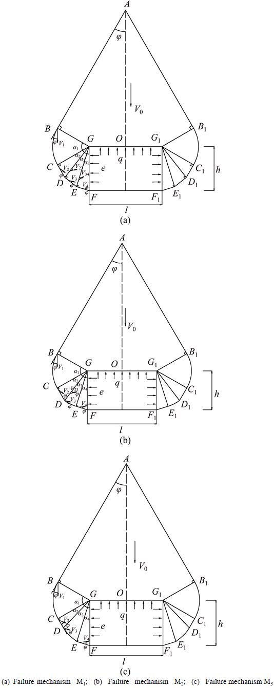
Fig. 1 Proposed failure mechanism in this work:

 (5)
(5)

 (6)
(6)

 (7)
(7)
 (8)
(8)
 (9)
(9)
 (10)
(10)
 (11)
(11)
 (12)
(12)
 (13)
(13)
 (14)
(14)
 (15)
(15)
The upper-bound solution of supporting pressure for M2 can be obtained as

 (16)
(16)
where the expressions of f1-f14 in the equation of supporting pressure for the failure mechanism M2 can be written as


 (17)
(17)

 (18)
(18)
 (19)
(19)


 (20)
(20)

 (21)
(21)

 (22)
(22)
 (23)
(23)
 (24)
(24)
 (25)
(25)
 (26)
(26)
 (27)
(27)

 (28)
(28)

(29)
 (30)
(30)
The upper-bound solution of supporting pressure for M3 is
 (31)
(31)
where the expressions of f1-f12 in the equation of supporting pressure for M3 can be written as


 (32)
(32)

(33)

 (34)
(34)


 (35)
(35)
 (36)
(36)
 (37)
(37)
 (38)
(38)
 (39)
(39)
 (40)
(40)
 (41)
(41)
 (42)
(42)
 (43)
(43)
In Eqs. (1)�C(43), �� is the soil unit weight, c is the cohesion, �� refers to the internal friction angle and K is the lateral pressure coefficient.
4 Comparisons among these three mechanisms
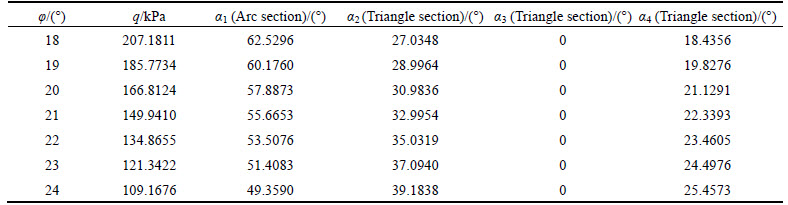
Numerous calculations are carried out with these three mechanisms in attempt to make a comparison. The numerical results of the supporting pressure and the corresponding optimal geometrical variables of failure mechanisms M1, M2 and M3 are presented respectively in Tables 1, 2 and 3 for the case of ��=20 kN/m3, h=l=10 m, c=10 kPa and K=1 with �� ranging in 18��-24��.
As seen in Table 2, for the failure mechanism M2,the optimal ��2 which corresponds to the triangle section between the two arcs is always equal to zero for all internal friction angle ��, which means that, for the optimal failure mechanism, the triangle does not exist and the two arcs are connected to one arc. As shown in Table 3, with respect to the failure mechanism M3, the optimal ��3 which corresponds to the log-spiral section is also always equal to zero for all cases. These two tables indicate that both the optimal failure mechanisms for M2 and M3 are composed of ��wedge section + arc section + triangle section��, just like the optimal mechanism of M1.
Table 1 Upper bound solution of supporting pressure and corresponding variables for M1
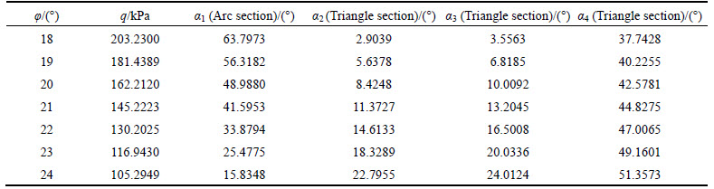
Table 2 Upper bound solution of supporting pressure and corresponding variables for M2
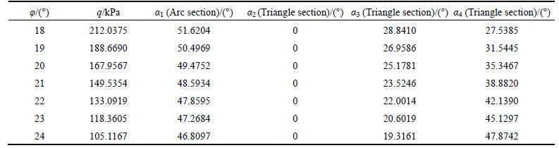
Table 3 Upper bound solution of supporting pressure and corresponding variables for M3
The values of supporting pressure from Tables 1-3 are plotted in Fig. 2 as a function of internal friction angle �� for three failure mechanisms. P1, P2 and P3 correspond to the supporting pressure for failure mechanisms M1, M2 and M3, respectively. It can be seen clearly in the Fig. 2 that critical supporting pressures with respect to failure mechanisms M1, M2 and M3 are very closely to each other. Therefore, based on the above discussions, a conclusion can be made that in the three failure mechanisms, all the optimal results lead to a basic shape for the failure mechanism under consideration, namely ��wedge collapsing block + rotating arc block + translational triangular blocks��.
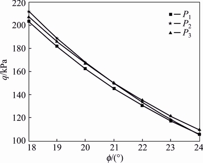
Fig. 2 Upper bound solution of supporting pressure for three failure mechanisms
5 An improved failure mechanism
On the basis of the aforementioned comparisons, an improved failure mechanism which is composed of ��a wedge block collapsing from the top of the cavity + an arc block rotating around the rectangular vertex + n translational triangular blocks�� is further discussed in this section. The ��three translational triangles�� in the M1 is extended to multiple triangles, as shown in Fig. 3.
The corresponding hodograph of the modified failure mechanism is shown in Fig. 4.
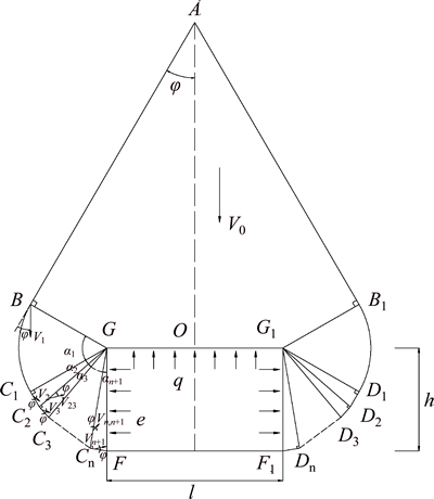
Fig. 3 Modified failure mechanism
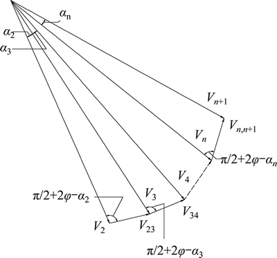
Fig. 4 Velocity vector diagram
The calculation of external power and internal energy dissipation are presented as followings.
5.1 Computation of external power
1) Power of soil gravity is as follows:


 (44)
(44)

 (45)
(45)


 (46)
(46)

 (47)
(47)

 (48)
(48)

 (49)
(49)

 (50)
(50)

 (51)
(51)

 (52)
(52)
2) The power of supporting pressure is as follows:
 (53)
(53)
 (54)
(54)
 (55)
(55)
3) The total external power equals to the sum of the power soil weight and supporting pressure:
 (56)
(56)
5.2 Internal energy dissipation
The energy dissipation along the velocity discontinuity AB is:
 (57)
(57)
 (58)
(58)
The energy dissipation on the arc radiation shear surface BC1 and over the arc radiation shear zone GBC1 are:
 (59)
(59)
 (60)
(60)
 (61)
(61)
 (62)
(62)
The energy dissipation along the velocity discontinuity  is:
is:
 (63)
(63)
The energy dissipation along the velocity discontinuity CnF is:
 (64)
(64)
 (65)
(65)
The energy dissipation along the velocity discontinuity  is:
is:
 (66)
(66)

 (67)
(67)
Therefore, the total energy dissipation is:

 (68)
(68)
The upper bound theorem of limit analysis requires that the power of external forces is equal to or less than the rate of energy dissipation. The upper bound supporting pressure can be derived:

 (69)
(69)
Above all of the formulas, h is the height of the cavity, measured in meter. l represents the width of the cavity, measured in meter. q is the vertical supporting pressure and e is the lateral supporting pressures with the unit of kPa. �� is the internal friction angle, measured in (��). �� is the soil unit weight, measured in kg/m3. c is the cohesion, measured in kPa. K is the lateral pressure coefficient. V0, V1, V2, ��, Vk, Vk+1 are the speeds in the velocity field. ��1, ��2, ��3, ��4, ��, ��n are the geometrical variables which determine the shape of the failure mechanism with the unit of (��). W is the external power; Wexit is the external total power; Wsoil is the weight power of surrounding rock; WT is the power of support of the anti force and their unit is W. W��, W��, Wk, Wn are variables. D is the dissipation power of internal energy; DAB, DBC1, DGBC, DiDi+1 (i=1, ��, n), DGC1, DCnF are respectively corresponding to the dissipation power of discontinuous lines, measured in W. g��, g ��, g���, f ��, f��, g0, g1, g2, ��, gk, ��, gn, f0, f1, f2, ��, fk, ��, fn, l1, l2, ��, lk, ��, ln are variables.
6 Numerical results and discussions
6.1 Discussion of number of triangles
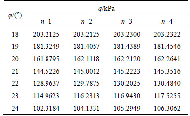
In order to study the influence of the number of triangles on the upper bound solutions of supporting pressures, several cases are calculated with n=1, 2, 3, 4 when ��=20 kN/m3, h=l=10 m, c=10 kPa, K=1. The calculated results are presented in Table 4. As listed in Table 4, the bigger the number of the triangle is, the higher value the upper bound solutions have which means that a higher number of the triangles lead to better upper bound solutions. But when n increases from 3 to 4, the change of results is very small, even negligible, with the maximum increase of 0.96% at ��=24, which means that n equating to 3 can meet the accuracy requirement.
Table 4 Upper bound supporting pressures for different n
6.2 Comparison with other methods
In order to validate the proposed failure mechanism, the supporting pressures calculated by the proposed failure mechanism are compared with those provided by Promojiyfakonov theory as well as the numerical simulation.
1) Comparison with analytical method
Table 5 presents the supporting pressures calculated by the upper bound limit analysis and Promojiyfakonov theory for the case of ��=20 kN/m3, h=l=10 m, ��=18. As seen in Table 5, there is a relatively reasonable agreement between these two methods, with the maximum difference of 26%.
2) Comparison with numerical simulation
The FLAC3D software is utilized to conduct the simulation for a deep cavity. The size of the numerical model is taken as 10D in the horizontal direction, 10D in the Y direction, vertical direction. Since it is a deep cavity, the gravitational variation of stress from top to bottom of the numerical model can be applied manually according to the depth of the cavity. In the numerical model, the two vertical and lower horizontal boundaries are set to be fixed. The soil is assumed to be Mohr-Coulomb material. The elastic properties are elastic modulus E=20 GPa and Poisson ratio v=0.3. These two parameters will not influence the critical supporting pressure. The bisection method reported by MOLLON et al [18] to calculate the critical collapse pressure is also utilized herein to calculate the critical supporting pressure.
Table 6 lists the supporting pressures calculated by the upper bound limit analysis and numerical method by FLAC3D for the case of ��=17 kN/m3, h=l=10 m, ��=18 and c varying from 10 kPa to 50 kPa. The results between these two methods show a good agreement, only with the maximum difference of 23% at c=30 kPa.
Figures 5 and 6 respectively show the plastic shear strain and the velocity field of the numerical simulation of deep cavity. From Figs. 5 and 6, the proposed failure mechanism agrees well with the plastic shear strain zone and the proposed velocity field also shows a good agreement with the numerical results, which means that the proposed failure mechanism is valid for the problem under consideration.
Table 5 Result comparison between upper bound limit analysis and Promojiyfakonov theory
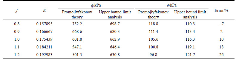
Table 6 Result comparison between upper bound limit analysis and numerical method

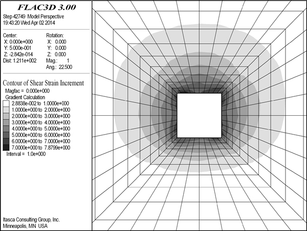
Fig. 5 Distribution of plastic shear strain of FLAC3D
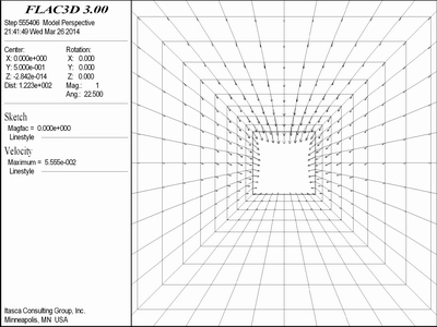
Fig. 6 Distribution of velocity field of FLAC3D
7 Project case
This section takes the Jiangyuanling Tunnel of the Tong-Ping Highway as an engineering example, which is located in the Pingjiang county, Hunan Province, China. The total length of the left tunnel is 1855 m and that of the right tunnel is 1785 m. The maximum buried depth of the tunnel is 800 m and the average buried depth is about 200 m. According to site survey, the mechanical parameters of rock mass are obtained as ��=18.5 kN/m3, c=0.05 MPa and ��=26��. In order to measure the surrounding rock pressure, soil pressure cells are buried at the vault and haunch between lining and surrounding rock. Through 45-d observation, the variation of surrounding pressure is obtained as illustrated in Fig. 7. It is found that the surrounding pressures of the vault and haunches increase within the first 30 d, and then tend to be a constant. The measured surrounding pressure of the vault is 52.1-53.4 kPa, and pressures of the left and right haunch are 48-49.1 kPa and 47.2-48.5 kPa, respectively. The surrounding pressure calculated by the proposed method in this work is 49.2 kPa for the vault and 44.3 kPa for the haunch. Compared with the measured data, the maximum errors respectively are 8%, 10% and 9%. The good consistency of obtained results verifies the rationality of the failure mechanism and the accuracy of the calculation method.
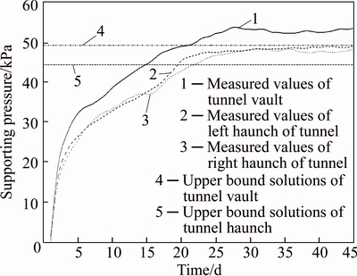
Fig. 7 Results comparison between field monitoring and this work
8 Conclusions
1) According to the kinematic approach of limit analysis, this work is devoted to the stability analysis of a deep cavity. Three failure mechanisms which comply with the kinematic admissible velocity field are proposed. The calculated results obtained from the three mechanisms show that the optimal failure mechanism turns into a basic shape which is composed of ��wedge collapsing block + rotating arc block + translational triangular blocks��.
2) The optimal failure mechanism is further improved by changing the three translational triangles into multiple ones according to the previous researches. The improved failure mechanism is constituted by ��a wedge block + a rotational arc block + n translational triangular blocks��. The impact of the number of triangular blocks on the supporting force is then discussed, which illustrates that a bigger n increases the precision of the upper bound solution. But when n>3, the influence is very negligible, so n=3 is taken in the later calculations.
3) The calculated results obtained by the proposed approach are compared with those provided by Promojiyfakonov theory, the numerical simulations by FlAC3D and field monitoring, which show a good agreement between them. This proves that the proposed failure mechanism is effective for the upper bound analysis of supporting pressure for deep cavity.
References
[1] SENENT S, MOLLON G, JIMENEZ R. Tunnel face stability in heavily fractured rock masses that follow the Hoek-Brown failure criterion [J]. International Journal of Rock Mechanics and Mining Sciences, 2013, 60(1): 440-451.
[2] YANG X L, XU J S, LI Y X, YAN R M. Collapse mechanism of tunnel roof considering joined influences of nonlinearity and non-associated flow rule [J]. Geomechanics and Engineering, 2016, 10(1): 21-35.
[3] SAADA Z, MAGHOUS S, GARNIER D. Pseudo-static analysis of tunnel face stability using the generalized Hoek-Brown strength criterion [J]. International Journal for Numerical and Analytical Methods in Geomechanics, 2013, 37(18): 3194-3212.
[4] YANG Xiao-li, YAO Cong, ZHANG Jia-hua. Safe retaining pressures for pressurized tunnel face using nonlinear failure criterion and reliability theory [J]. Journal of Central South University, 2016, 23(3): 708-720.
[5] MICHALOWSKI R L, DRESCHER A. Three-dimensional stability of slopes and excavations [J]. Geotechnique, 2009, 59(10): 839-850.
[6] MICHALOWSKI R L, NADUKURU S S. Three-dimensional limit analysis of slopes with pore pressure [J]. Journal of Geotechnical and Geoenvironmental Engineering, 2012, 139(9): 1604-1610.
[7] YANG X L, HUANG F. Collapse mechanism of shallow tunnel based on nonlinear Hoek-Brown failure criterion [J]. Tunnelling and Underground Space Technology, 2011, 26(6): 686-691.
[8] YANG X L, HUANG F. Three-dimensional failure mechanism of a rectangular cavity in a Hoek-Brown rock medium [J]. International Journal of Rock Mechanics and Mining Sciences, 2013, 61(10): 189-195.
[9] YANG X L, LONG Z X. Seismic and static 3D stability of two-stage rock slope based on Hoek-Brown failure criterion [J]. Canadian Geotechnical Journal, 2016, 53(3): 551-558.
[10] YANG X L, YIN J H. Slope stability analysis with nonlinear failure criterion [J]. Journal of Engineering Mechanics, 2004, 130(3): 267-273.
[11] CHEN W F. Limit analysis and soil plasticity [M]. Florida: J Ross Publishing, Inc, 2007.
[12] ATKINSON J H, POTTS D M. Stability of a shallow circular tunnel in cohesionless soil [J]. Geotechnique, 1977, 27(2): 203-215.
[13] DAVIS E H, DUNN M J, MAIR R J, SENEVIRATINE H N. The stability of shallow tunnels and underground openings in cohesive material [J]. Geotechnique, 1980, 30(4): 397-416.
[14] SLOAN S W, ASSADI A. Stability of shallow tunnels in soft ground [C]// Proceedings of the Wroth Memorial Symposium. London: Thomas Telford House, 1993: 644-663.
[15] OSMAN A S, MAIR R J, BOLTON M D. On the kinematics of 2D tunnel collapse in undrained clay [J]. Geotechnique, 2006, 56(9): 585-595.
[16] KLAR A, OSMAN A S, BOLTON M. 2D and 3D upper bound solutions for tunnel excavation using ��elastic�� flow fields [J]. International Journal for Numerical and Analytical Methods in Geomechanics, 2007, 1(31): 1367-1374.
[17] YANG Yu-you, LI Hong-an. Failure mechanism of large-diameter shield tunnels and its effects on ground surface settlements [J]. Journal of Central South University, 2012, 19(10): 2958-2965.
[18] MOLLON G, PHOON K K, DIAS D, SOUBRA A H. Validation of a new 2D failure mechanism for the stability analysis of a pressurized tunnel face in a spatially varying sand [J]. Journal of Engineering Mechanics, 2010, 137(1): 8-21.
[19] MOLLON G, DIAS D, SOUBRA A H. Rotational failure mechanisms for the face stability analysis of tunnels driven by a pressurized shield [J]. International Journal for Numerical and Analytical Methods in Geomechanics, 2011, 35(12): 1363-1388.
[20] MOLLON G, DIAS D, SOUBRA A H. Range of the safe retaining pressures of a pressurized tunnel face by a probabilistic approach [J]. Journal of Geotechnical and Geoenvironmental Engineering, 2013, 139(11): 1954-1967.
[21] YANG X L, DU D C. Upper bound analysis for bearing capacity of nonhomogeneous and anisotropic clay foundation [J]. KSCE Journal of Civil Engineering, 2016, 20(7): 2702-2710.
[22] LI Y X, YANG X L. Stability analysis of crack slope considering nonlinearity and water pressure [J]. KSCE Journal of Civil Engineering, 2016, 20(6): 2289-2296.
[23] YANG X L, PAN Q J. Three dimensional seismic and static stability of rock slopes [J]. Geomechanics and Engineering, 2015, 8(1): 97-111.
[24] ZHAO Y L, ZHANG L Y, WANG W J. Cracking and stress-strain behavior of rock-like material containing two flaws under uniaxial compression [J]. Rock Mechanicsw and Rock Engineering, 2016, 49(7): 2665-2687.
[25] ZHAO Y L, ZHANG L Y, WANG W J. Transient pulse test and morphological analysis of single rock fractures [J]. International Journal of Rock Mechanics and Mining Sciences, 2017, 91(1): 139-154.
(Edited by YANG Hua)
Cite this article as:
ZHANG Dao-bing, LIU Zhi-zhen, ZHANG Jia-hua. A new failure mechanism for deep cavity and upper bound solution of supporting pressure [J]. Journal of Central South University, 2017, 24(9): 2082�C2091.
DOI:https://dx.doi.org/https://doi.org/10.1007/s11771-017-3617-3Foundation item: Project(51674115) supported by the National Natural Science Foundation of China; Project(51434006) supported by the Key Program of the National Natural Science Foundation of China; Project(2015JJ4024) supported by the Natural Science Foundation of Hunan Province, China
Received date: 2016-09-06; Accepted date: 2016-12-01
Corresponding author: ZHANG Dao-bing, PhD; Tel: +86-13975264336; E-mail: dbzhang@hnust.edu.cn
Abstract: The investigation of supporting pressure is of great significance to the design of underground structures. Based on the kinematical approach of limit analysis, an improved failure mechanism is proposed, and the supporting pressure is investigated for deep buried cavity. Three failure mechanisms are first introduced according to the existing failure mechanisms of geotechnical structures of limit analysis. A comparison with respect to the optimal failure mechanisms and the upper bound solutions provided among these three mechanisms are then conducted in an attempt to obtain the improved failure mechanism. The results provided by the improved failure mechanism are in good agreement with those by the existing method, the numerical solution and field monitoring, which demonstrates that the proposed failure mechanism is effective for the upper bound analysis of supporting pressure.
