
Trans. Nonferrous Met. Soc. China 27(2017) 2334-2344
Parametric optimization of friction stir welding parameters of marine grade aluminium alloy using response surface methodology
S. SHANAVAS1, J. EDWIN RAJA DHAS2
1. Department of Mechanical Engineering, Noorul Islam University, Tamil Nadu, India;
2. Department of Automobile Engineering, Noorul Islam University, Tamil Nadu, India
Received 24 September 2016; accepted 30 December 2016
Abstract:
Friction stir welding between AA5052-H32 aluminium plates is performed by central composite design technique of response surface methodology. It is found that the welding parameters such as tool pin profile, tool rotational speed, welding speed, and tool tilt angle play a major role in deciding the joint characteristics. The joints fabricated using tapered square pin profile tool with a tool rotational speed of 600 r/min, welding speed of 65 mm/min, and tool tilt angle of 1.5�� result in an unexpected weld efficiency of 93.51%. Mathematical models are developed to map the correlation between the parameters and responses (ultimate tensile strength and elongation) and these models are optimized to maximize the ultimate tensile strength of the friction stir welded joint. Response plots generated from the mathematical models are used to interpret the interaction effects of the welding parameters on the response variables. Adequacy of the developed models is validated using analysis of variance (ANOVA) technique. Results from the confirmatory experiments plotted in scatter diagram show a good agreement with predicted models. Different grain structures in various zones of the weld are examined by observing the micro and macro structures of the weld.
Key words:
aluminum alloy 5052; friction stir welding; response surface method; tensile strength; microstructure;
1 Introduction
High specific strength and corrosion resistance necessitate the use of aluminium alloy in making lighter, faster, and stronger high-performance vessels. Aluminum alloys widely used for marine applications are 5xxx series in which the principal alloying element is magnesium. These alloys are now used as an alternative to steel in many applications because of their light weight, good weldability, good formability, high strength, and high corrosion resistance [1,2]. Among the AA5xxx series of aluminium alloys, AA5052-H32 aluminium alloys are excellent in corrosion resistance and therefore are particularly suited for applications in the industrial and marine environment. Welds of these alloys are normally as corrosion resistant as the parent material. Till 1991, the welding of aluminium and its alloys was a great challenge for researchers and technologists. Friction stir welding (FSW) is relatively new solid state joining process patented in 1991 [1]. The process is used in various industries like aerospace, marine and automobile, due to its high-quality joints [3].
Weld parameters such as tool pin profile, rotational speed, welding speed, and tool tilt angle, are key factors that govern the heat generation and stirring required to join the material effectively [4-6]. Influence of tool pin profile and welding speed on the formation of friction stir processing zone in AA2219 aluminium alloy [7], AA6061 aluminium alloy [8] and AA7075 aluminium alloy [9] is investigated. It is found that the tapered pin profile exhibited superior tensile properties compared to straight pin profile for AA7039 aluminium [10]. AA5052-H32 aluminium alloy is highly corrosion resistance stabilized aluminium alloy used for automotive and marine structural applications. Limited works are carried out on friction stir welding between AA5052-O aluminium alloy plates [11-13]. Studies were done on the effect of tool shoulder diameter on heat input during FSW of AA5052-H32 alloy [14]. The effect of tool rotational speed and tool tilt angle on the mechanical properties and metallographs of the dissimilar friction stir butt joint between Al alloy AA5052-H32 and HSLA steel [15] were investigated.
Various experimental design methods are available to predict the response under a given set of operating parameters accurately and efficiently. Taguchi method is such a method, which uses an orthogonal array to cut down the number of experiments. The major drawback of this method is a few interactions with variables, and this can be overcome by the response surface method [16]. Nowadays, researchers prefer response surface design to develop an empirical relationship to predict the responses [17-19]. Therefore, in this work, an attempt has been made to optimize the FSW process parameters to maximize the tensile strength of AA5052-H32 aluminium alloy joints using the central composite design technique of response surface methodology. Mathematical models are developed to predict the response. Microstructures are examined on the welded specimen and the reports are presented.
2 Experimental
It is very difficult to form a mathematical equation for higher tensile strength values so that we consider the range of friction stir parameters. The predominant factors that influence the joint properties and the working ranges of those factors of AA5052-H32 aluminium alloy are presented in Table 1. Due to wide range of influencing factors, it is decided to design four significant factors, five levels and a central composite response surface method design matrix with 31 runs. So, many trial welds were carried out to fix the working ranges of all selected parameters. The upper limit of these factors was coded as +2 and the lower limit as -2. The intermediate values are calculated using the relationship:
Xi=2[2X-(Xmax+Xmin)]/(Xmax-Xmin) (1)
where Xi is the required coded value of variable X, X is any value of the variable from Xmin to Xmax, Xmin is the lowest level of the variable and Xmax is the highest.
The 31 sets of coded conditions comprise a half replication of 24=16 factorial design with 7 center points and 8 axial/start points. All the welding parameters at the middle level (0) constitute center points, whereas the combinations of each welding parameter at its lower value (-2) or higher value (+2) with the other four parameters at the middle level constitute the star points. Thus, the 31 experimental runs allowed the estimation of linear, quadratic and two-way interactive effects of the welding parameters on the ultimate tensile strength.
In the present work, 150 mm �� 50 mm �� 6 mm cold rolled plates of high strength aluminium magnesium alloy AA5052-H32 were used for friction stir welding experiments. The chemical composition of the metal is given in Table 2. Wire brushing is employed for cleaning the abutting surfaces for welding. The welding direction was parallel to the rolling direction of the plate. The plates were welded in a single pass, using tapered tool pin profiles such as cylindrical tapered, hexagon tapered, pentagon tapered, square tapered, and triangular tapered having a taper angle of 10�� and pin length of 5.7 mm (Fig. 1). Considering the weld quality of AA5052-H32 aluminium plates and tool wear rate, H13 steel was selected for this work [20-22]. As prescribed by the design matrix, totally 31 joints of each alloy were fabricated. Photographs of the fabricated joints are displayed in Fig. 2.
Table 1 Identified significant factors and their levels
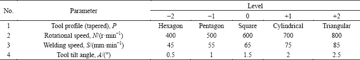
Table 2 Chemical compositions of Al5052-H32 alloy (mass fraction, %)

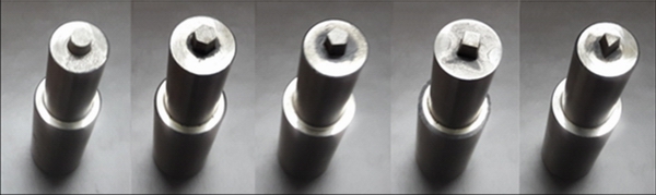
Fig. 1 Various tool pin profiles used for welding study

Fig. 2 Photographs of FS welded joints by different FSW parameter combinations
ASTM-E8 standard was followed for conducting the tensile test [23]. Tensile tests were carried out by UTM, DAK-UTB 9103 with 100 kN capacities. For microstructure examination, cross sections of the welded joints cut by EDM were progressively ground using different grades of emery paper, then polished using diamond paste and finally etched with Keller reagent. Microstructures were determined by metallurgical microscope, QS metrology�CXJL17, Japan, made at different magnifications.
3 Mathematical models
Thirty-one treatments in Table 3 are used as input data to form a mathematical equation by the design of experiment method, using response surface methodology. The response function, ultimate tensile strength (��s) and elongation (��) of the joints are functions of the tool profile (P), rotational speed (N), welding speed (S) and tool tilt angle (A). It is expressed as
��s=f (P, N, S, A) (2)
��=f (P, N, S, A) (3)
The second order polynomial regression equation used to represent the response surface is given by
Y=b0+��bixi+��biixi2+��bijxixj (4)
The selected polynomial for four factors can be expressed as
Y=b0+b1P+b2N+b3S+b4A+b11P2+b22N2+b33S2+b44A2+b12P��N+b13P��S+b14P��A+b23N��S+b24N��A+b34S��A (5)
where b0 is the average of responses, the coefficients b1, b2, b3 and b4 are linear terms, the coefficients b11, b22, b33 and b44 are quadratic terms, and the coefficients b12, b13, b14, b23, b24 and b34 are interaction terms. All the coefficients were evaluated and tested for their significance at a 95% confidence level. The final mathematical model developed to predict the ultimate strength and elongation of FSW joints of the AA5052-H32 aluminium alloy is given as
��s=200.275-3.484P-0.080N-1.231S+5.068A-2.555P2-2.003N2-1.040S2-3.230A2+0.185P��N-0.530P��S+2.457P��A-0.474N��S+0.960N��A+1.438S��A (6)
��=24.635-0.587P-0.314N-1.329S+3.001A-1.908P2-1.631N2-0.416S2-1.092A2+0.404P��N-0.092P��S+0.979P��A-0.412N��S+0.440N��A-0.541S��A (7)
Table 3 Design matrix and experimental results

4 Results and discussion
4.1 Tensile test
Photographs of the tensile tested 32 specimens (a base metal and 31 joints) are displayed in Fig. 3. The advancing side and retreating side of the welded specimens are labeled as AS and RS, respectively, and the base metal is labeled as BM. The joints fabricated using tapered square pin profile tool with a rotational speed of 600 r/min, welding speed of 65 mm/min, and tilt angle of 1.5�� (Run 30) exhibits maximum tensile strength compared to other joints. The maximum efficiency obtained from the experiment is 93.51%. These joints fracture at the retreating side of the welded joint. This is due to good bonding at the stir zone with optimum heat generation and strain rate. The heat generation and material consolidation are less at the retreating side compared to the advancing side, which leads to the fracture of the joint at retreating side. The joints fabricated using tapered square pin profile tool with a rotational speed of 600 r/min, welding speed of 65 mm/min, and tilt angle of 0.5�� (Run 23) exhibits minimum tensile strength compared to other joints.

Fig. 3 Photographs of tensile tested specimens
These joints fracture at the stir zone of the welded joint. This is due to poor bonding at the stir zone with very low frictional heat generation. The results show that the tool tilt angle has a significant role in determining the tensile strength of the welded joint.
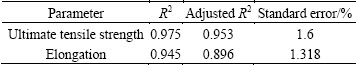
4.2 Adequacy of developed empirical models
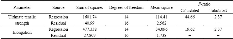
The statistical results of the developed empirical relationship are tabulated in Table 4. When R2 value is 1, the predicted empirical relationship value perfectly matches with the experimental value. The higher value of R2 towards 1 and lower value of standard error indicate that the empirical relationships are quite adequate and can be used to predict the responses without considerable error. Higher adjusted R2 value increases variation and indicates more useful variables in the model. The statistical result gives a higher R2 value of 0.975 and 0.945 and adjusted R2 value of 0.953 and 0.896 for the ultimate tensile strength and elongation, respectively, indicating that a very high degree of a match exists between the predicted empirical relationship and experimental value. This validates the experimental value. The adequacy of developed models was tested using the analysis of variance technique (ANOVA) which is presented in Table 5. According to ANOVA, if the calculated value of F-ratio of the model exceeds the tabulated value of F-ratio at 95% confidence level, then the model can be considered as adequate. Table 5 reveals that the calculated value of F-ratio of the tested model is very higher than the tabulated value of F-ratio at 95% confidence level indicating that the developed models are adequate.
Table 4 Statistical results
4.3 Validation of empirical result
The validity of the empirical relationships is tested by drawing scatter diagram with the experimental value and predicted value on x-axis and y-axis, respectively, as shown in Fig. 4. The scattered plots are very close to 45�� line, which indicates the perfect fitness of the developed empirical relationships. Experiments were conducted to confirm the validity of developed empirical relationships.
Table 5 Results from ANOVA
Five welds were made using different values of factors other than those used in design matrix and their ultimate tensile strength and elongation were estimated. The obtained results are given in Table 6. The result shows that the predicted values are quite adequate without appreciable error.
4.4 Analysis of macro and microstructures
Figure 5 shows the optical macrograph of the cross section perpendicular to the tool transverse direction of the welded specimen with high tensile strength. Defects such as voids, cracks and unbonded zones are not observed in and around the stir zone. Figure 6 shows the optical microstructure of the base metal (BM), the heat hazard zone (HAZ), the thermo-mechanically affected zone (TMAZ) and the stir zone (SZ)/the weld nugget zone (WNZ) on the cross section perpendicular to the tool transverse direction of the welded specimen with high tensile strength. In the base metal, the grain size is not uniformed, elongated or non-equiaxed and found large at 10 ��m in size, as shown in Fig. 6. But, the WNZ is composed of smaller and equiaxed grains. This suggests that the WNZ is severely plastically deformed by the mechanical stirring action of the rotating probe of the tool during the FSW process and the grain refinement occurs as a result of dynamic recrystallization. Distortion of the microstructure occurs at the BM due to the cold working of aluminium alloy.
4.5 Analysis of response surface plots and contour plots
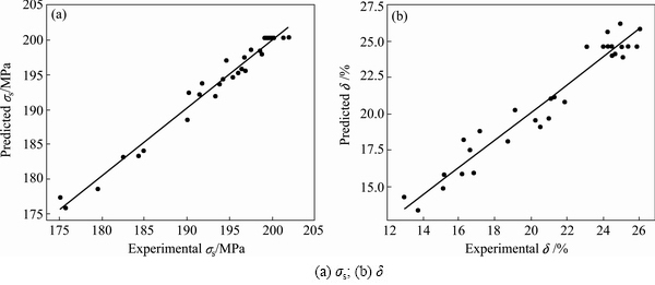
Fig. 4 Experimental vs predicted values of responses

Fig. 5 Cross sectional macrograph of welded specimen with high tensile strength
Table 6 Results from confirmatory experiments
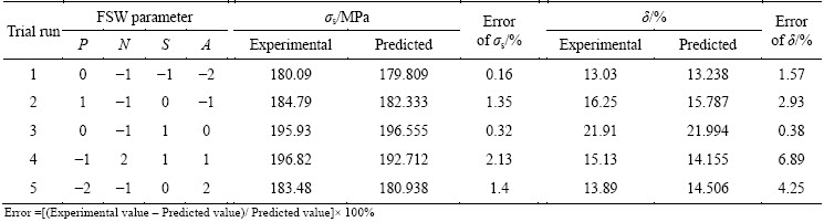

Fig. 6 Optical micrographs of base metal (a, b), HAZ (c), TMAZ (d) and WNZ/SZ (e, f)
Figure 7 represents three-dimensional response surface plots for the response (ultimate tensile strength) obtained from the regression model. The optimum ultimate tensile strength is exhibited by the apex of the response surfaces. It is easier to understand the interactions of factors on the response by examining the contour plots. Figure 8(a) exhibits an almost circular contour, which suggests independence of factor effects, namely tool pin profile and the rotational speed at constant center points of 65 mm/min welding speed and 1.5�� tool tilt angle. Figure 8(b) shows that the change in the tool pin profile is slightly more sensitive to the change in ultimate tensile strength than the change in welding speed at constant center points of 600 r/min rotational speed and 1.5�� tool tilt angle. Figure 8(c) shows that the changes in both tool tilt angle and tool pin profile affect the ultimate tensile strength at constant center points of 600 r/min rotational speed and 65 mm/min welding speed. Figure 8(d) shows that the change in rotational speed is slightly more sensitive to the change in ultimate tensile strength than the change in welding speed at constant center points of tapered square tool pin profile and 1.5�� tool tilt angle. Figure 8(e) shows that the changes in both tool tilt angle and rotational speed affect the ultimate tensile strength at constant center points of tapered square tool pin profile and 65 mm/min welding speed. Figure 8(f) exhibits that the change in the tool tilt angle is more sensitive to the change in ultimate tensile strength than the change in welding speed at constant center points of tapered square tool pin profile and 600 r/min rotational speed. It is also observed from Fig. 8 that, in all the conditions at maximum ultimate tensile strength, the rotational speed is found at the center point of 600 r/min.
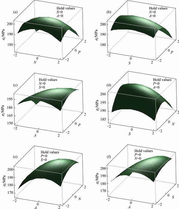
Fig. 7 Response surface plots of weld parameters and ��s
4.6 Analysis of direct effects and main interaction effects of welding parameters
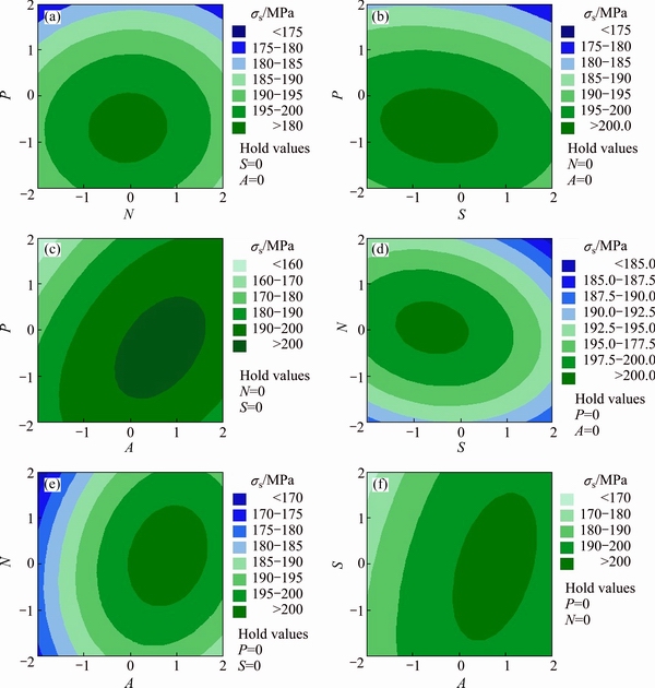
Fig. 8 Contour plots of weld parameters and ��s
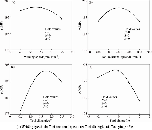
Fig. 9 Direct effects of welding parameters on ��s
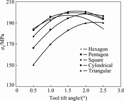
Fig. 10 Interaction effects of P and A on ��s
The ultimate tensile strength increases directly with the tool rotational speed, welding speed, and tool tilt angle, and then decreases after it reaches the maximum value (Fig. 9). The results show that the tool tilt angle and tool pin profile have a significant role in determining the tensile strength of the welded joint. The decrease in tool tilt angle leads to poor bonding due to high frictional heat generation and the increase in tilt angle leads to poor bonding due to very low frictional heat generation. Tapered square pin profile tool exhibits maximum ultimate tensile strength and tapered triangular pin profile tool exhibits minimum ultimate tensile strength. The change in tool pin profile changes the shear stress thereby varying friction within the weld metal, and the heat generates. The layer by layer material consolidation at stir zone due to insufficient heat reduces the strength of the joint. Higher and lower tool rotational speeds lead to poor bonding due to high frictional heat generation and low frictional heat generation, respectively. Higher and lower welding speeds lead to poor bonding due to very low frictional heat generation and high frictional heat generation, respectively. The optimum heat generation leads to plasticized flow, and the materials in the weld diffuse and recrystallize, thereby creating a qualified joint. Figure 10 shows the interaction effects of tool pin profile and tool tilt angle on ultimate tensile strength. The results reveal that for all the tool pin profiles except the tapered triangular tool pin profile, the increase in tool tilt angle initially increases the tensile strength, and then decreases after reaching the maximum value. For the tapered triangular tool pin profile, the increase in tool tilt angle leads to increase in tensile strength and at most tilt angles it exhibits minimum tensile strength compared to other tool pin profiles. This is because of high heat generation while using the triangular tapered tool pin profile. At 0.5�� tilt angle, the heat generation is high; while with an increase in tilt angle to 2.5��, the high heat generation gets reduced and leads to increase in tensile strength. The maximum tensile strength is obtained for the tapered square pin profiled tool with tool tilt angle of 1.5�� and 2��. Figure 11 shows the interaction effects of welding speed and tool tilt angle on ultimate tensile strength. The results reveal that for all the welding speed, the increase in tool tilt angle initially increases the tensile strength, reaches a maximum value and then decreases. At 0.5�� tilt angle, the heat generation is more. The increase in welding speed at 0.5�� tilt angle decreases the heat generation and the tensile strength. This shows that the welding speed is inversely proportional to the tensile strength at 0.5�� tilt angle. The proportionality changes as the tilt angle increases and the maximum tensile strength is obtained at a welding speed of 65 mm/min with tool tilt angle of 1.5��. The result also suggests avoiding higher welding speed at a lower tilt angle.
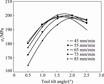
Fig. 11 Interaction effects of S and A on ��s
4.7 Optimization of welding parameters
Optimization of the welding parameters to maximize ultimate tensile strength was carried out by using Excel solver tool. The regression equation obtained from mathematical modeling is used as an objective function. Constraints are fixed to limit the values of the parameters used in the function. The optimum values of welding parameters for the predicted ultimate tensile strength of 202.58 MPa are rotational speed of 613 r/min (0.13), traverse speed of 64 mm/min (-0.08), tool tilt angle of 1.8�� (0.62), and tapered square tool pin profile (-0.35).
5 Conclusions
1) Empirical relationships were built to estimate the response such as ultimate tensile strength and elongation of friction stir AA5052-H32 aluminium alloy. The ANOVA analysis shows that the developed model can be effectively used to predict the responses of the joints at 95% confidence level. Trials were carried out to validate the results.
2) Based on the regression models, the effects of operating parameters on ultimate tensile strength and elongation of the friction stir welded joints were presented and interpreted.
3) The joints fabricated using tapered square pin profile tool with a rotational speed of 600 r/min, welding speed of 65 mm/min, and tilt angle of 1.5�� exhibited superior tensile properties compared to other joints. The tapered square tool pin profile produced a higher pulsating effect and smooth material flow, which resulted in the highest tensile strength and elongation.
4) The tensile test results reveal that the tool tilt angle has a significant role in determining the tensile strength of the welded joint. The increase in the tool tilt angle leads to the better consolidation of the material under shoulder and the mechanical properties get increased.
5) From the macro and microstructure study, a defect-free weld is observed in and around the stir zone. The grain refinement occurred at the stir zone as a result of dynamic recrystallization.
6) From the contour plots, it is identified that in all interaction effect of factors, the rotational speed is found fixed at the center point of 600 r/min for maximum tensile strength. The tool rotational speed has no significant interaction effect on the tensile strength of the joint in the range considered for modeling (400-800 r/min).
7) The welding parameters were optimized for the predicted maximum tensile strength.
References
[1] MOSHWAN R, YUSOF F, HASSAN M A, RAHMAT S M. Effect of tool rotational speed on force generation, microstructure and mechanical properties of friction stir welded AA 5052-O alloy [J]. Materials and Design, 2015, 66: 118-128.
[2] CHEN Jian-bin, YUAN Xin-jian, HU Zhan, SUN Chang-zheng, ZHANG Yan-xin, ZHANG Yu-xuan. Microstructure and mechanical properties of resistance-spot-welded joints for A5052 aluminum alloy and DP 600 steel [J]. Materials Characterization, 2016, 120: 45-52.
[3] MISHRA R S, MA Zong-yi. Friction sir welding and processing [J]. Material Science and Engineering R, 2005, 50: 1-78.
[4] GRIMM A, SCHULZE S, SILVA A, GOBEL G, STANDFUSS J, BRENNER B, BEYER E, FUSSEL U. Friction stir welding of light metals for industrial applications [J]. Materials Today: Proceedings, 2015, 2: s169-s178.
[5] ANAND A, KHAJURIA A. Welding processes in marine application: A review [J]. International Journal of Mechanical Engineering and Robotics Research, 2015, 2: 215-225.
[6] ELATHARASAN G, SENTHIL KUMAR V S. An experimental analysis and optimization of process parameter on friction stir welding of AA 6061-T6 aluminium alloy using RSM [J]. Procedia Engineering, 2013, 64: 1227-1234.
[7] ELANGOVAN K, BALASUBRAMANIAN V. Influence of tool pin profile and welding speed on the formation of friction stir processing zone in AA2219 aluminium alloy [J]. Journal of Materials Processing Technology, 2008, 200: 163-175.
[8] PRASANNA P, PENCHALAYYA C H, ANANDAMOHANA RAO D. Effect of tool pin profiles and heat treatment process in the friction stir welding of AA 6061 aluminium alloy [J]. American Journal of Engineering Research, 2013, 2: 7-15.
[9] BAYAZID S M, FARHANGI H, GHAHRAMANI A. Effect of pin profile on defects of friction stir welded 7075 aluminum alloy [J]. Procedia Materials Science, 2015, 11: 12-16.
[10] UGENDER S, KUMAR A, SOMI REDDY A. Experimental investigation of tool geometry on mechanical properties of friction stir welding of AA 2014 aluminium alloy [J]. Procedia Materials Science, 2014, 5: 824-831.
[11] KWON Yong-Jai, SHIM Seong-Beom, PARK Dong-Hwan. Friction stir welding of 5052 aluminum alloy plates [J]. Transactions of Nonferrous Metals of China, 2009, 19: 23-27.
[12] ABHIJEET B, DILIP M. A comprehensive study of an aluminum alloy Al-5052 [J]. Advance Physics Letter, 2016, 3: 20-22.
[13] GUDIC S, VRSALOVIC L, KLISKIC M, JERKOVIC I, RADONIC A, ZEKIC M. Corrosion inhibition of AA 5052 aluminium alloy in NaCl solution by different types of honey [J]. International Journal of Electrochemical Science, 2016, 11: 998-1011.
[14] TUFARO L N, MANZONI I, SVOBODA H G. Effect of heat input on AA5052 friction stir welds characteristics [J]. Procedia Materials Science, 2015, 8: 914-923.
[15] RAMACHANDRAN K K, MURUGAN N, SHASHI KUMAR S. Friction stir welding of aluminum alloy AA5052 and HSLA steel [J]. Welding Journal, 2015, 94: 291-300.
[16] MONTGOMERY D C. Design and analysis of experiments [M]. 8th ed. New York: John Wiley and Sons, 2013.
[17] BINOY K B, PRADIP K P, ASISH B. Optimization of process parameters for flux cored arc welding of boiler quality steel using response surface methodology and grey-based Taguchi methods [J]. International Journal of Materials, Mechanics and Manufacturing, 2016, 4: 8-16.
[18] SELVAMANI S T, DIVAGAR S, VIGNESHWAR M. Application of response surface methodology (RSM) in friction welding AISI 1020 grade steel joints [J]. International Journal of Engineering Research in Africa, 2015, 16: 38-44.
[19] RAMANJANEYULU K, MADHUSUDHAN R G, HINA G. Optimization of process parameters of aluminum alloy AA 2014-T6 friction stir welds by response surface methodology [J]. Defence Technology, 2015, 11: 209-219.
[20] VENKATESWARLU D, MANDAL N R, MAHAPATRA M M, HARSH S P. Tool design effects for FSW of AA7039 [J]. Welding Research, 2013, 92: 41-47.
[21] RAI R, DE A, BHADESHIA H K D H, DEBROY T. Review: Friction stir welding tools [J]. Science and Technology of Welding and Joining, 2011, 16: 325-342.
[22] BIST A, SAINI J S, SHARMA B. A review of tool wear prediction during friction stir welding of aluminium matrix composite [J]. Transactions of Nonferrous Metals Society of China, 2016, 26: 2003-2018.
[23] ASTM E8/E8M-09. Standard test methods for tension testing of metallic materials [S]. ASTM International, 2010.
������Ӧ�淨��AA5052-H32���Ͻ����Ħ���������Ż�
S. SHANAVAS1, J. EDWIN RAJA DHAS2
1. Department of Mechanical Engineering, Noorul Islam University, Tamil Nadu, India;
2. Department of Automobile Engineering, Noorul Islam University, Tamil Nadu, India
ժ Ҫ������������������Ӧ�淽����AA5052-H32�����Ľ���Ħ�������̽����Ż����о����֣����Ӳ��������ͷ��״������ͷת�١������ٶȺͽ���ͷ��б�ǶԽ�ͷ�������ž������á����÷��ν���ͷ���ڽ���ͷת��Ϊ600 r/min�������ٶ�Ϊ65 mm/min�ͽ���ͷ���Ϊ1.5��ʱ���õ����ŵĺ���Ч��93.51%��������ѧģ���������Ӳ�������Ӧ����(������ǿ�Ⱥ��쳤��)��Ĺ�ϵ������ģ�ͽ����Ż���������ȵ���߽���Ħ������ͷ�ļ�����ǿ�ȡ�������ѧģ��������Ӧ�����Խ��ͺ��Ӳ�������Ӧ�������Ӱ�죬�����÷������(ANOVA)��֤ģ�͵Ŀɿ��ԡ����������ʵ��������Ԥ��ģ���ǺϽϺá�ͨ���۲캸����ۺͺ�۽ṹ���о����첻ͬ����ľ�����֯��
�ؼ��ʣ�AA5052���Ͻ𣻽���Ħ��������Ӧ�淨������ǿ�ȣ�����֯
(Edited by Bing YANG)
Corresponding author: S. SHANAVAS; Tel: +91-9400529829; E-mail: shanavas.in@gmail.com
DOI: 10.1016/S1003-6326(17)60259-0
Abstract: Friction stir welding between AA5052-H32 aluminium plates is performed by central composite design technique of response surface methodology. It is found that the welding parameters such as tool pin profile, tool rotational speed, welding speed, and tool tilt angle play a major role in deciding the joint characteristics. The joints fabricated using tapered square pin profile tool with a tool rotational speed of 600 r/min, welding speed of 65 mm/min, and tool tilt angle of 1.5�� result in an unexpected weld efficiency of 93.51%. Mathematical models are developed to map the correlation between the parameters and responses (ultimate tensile strength and elongation) and these models are optimized to maximize the ultimate tensile strength of the friction stir welded joint. Response plots generated from the mathematical models are used to interpret the interaction effects of the welding parameters on the response variables. Adequacy of the developed models is validated using analysis of variance (ANOVA) technique. Results from the confirmatory experiments plotted in scatter diagram show a good agreement with predicted models. Different grain structures in various zones of the weld are examined by observing the micro and macro structures of the weld.
