
Trans. Nonferrous Met. Soc. China 30(2020) 1916-1927
Three-dimensional upper bound limit analysis of underground cavities using nonlinear Baker failure criterion
Zhi-zhen LIU1, Ping CAO1, Hang LIN1, Jing-jing MENG2, Yi-xian WANG3
1. School of Resources and Safety Engineering, Central South University, Changsha 410083, China;
2. Department of Civil, Environmental and Natural Resources Engineering, Lulea University of Technology, Lulea, Sweden;
3. School of Civil Engineering, Hefei University of Technology, Hefei 230009, China
Received 31 October 2019; accepted 1 June 2020
Abstract:
A generalized nonlinear Baker failure criterion is employed with the upper bound limit analysis to study the surrounding rock stability of underground cavities. A three-dimensional (3D) failure mode is established by extending the two-dimensional (2D) failure mode, which offers an upper bound expression of the surrounding rock pressure. This method is validated with a series of examples before the influence of four parameters of scale parameter, curvature parameter, shift parameter and lateral pressure coefficient, on the surrounding rock pressure is analyzed. According to these results, failure ranges of the underground cavities are determined. The following conclusions are reached: (1) the proposed approach is more accurate to predict surrounding rock pressure than the Mohr-Coulomb failure criterion; (2) the surrounding rock with large scale parameter, curvature parameter, shift parameter, and lateral pressure coefficient can lead to a more stable underground cavity; (3) the failure range in 3D mode can be predicted according to the upper bound solutions.
Key words:
Baker failure criterion; underground cavity; surrounding rock pressure; 3D failure mode; upper bound limit analysis;
1 Introduction
Underground cavities such as tunnels, road- ways and storages are constructed continuously. The support systems need to be properly designed to ensure enough supporting pressures. Therefore, it is imperative to determine the ultimate supporting pressure, i.e., critical failure pressure to prevent risks such as surrounding rock collapse. For this purpose, numerical methods (e.g., discontinuity layout optimization method [1-3], finite element method [4-8], discrete element method [9], rigid blocks method [10,11] and the limit analysis method [12,13]), in-situ testing [14] and laboratory testing [15-22] can be employed. The discontinuity layout optimization can be used to determine the critical layout of discontinuities and associated upper-bound limit load for plane plasticity problems [1-3]. The finite element method allows to simulate the construction sequence, ground displacements and stress patterns around the tunnel. In Ref. [9], a new framework of discontinuous deformation analysis was proposed and the failure of a cavity was simulated. The rigid blocks method assumes that the failure mechanism is composed of rigid blocks and its energy dissipation can occur only on the velocity discontinuities [10,11]. When comparing to the above mentioned methods, field tests are rarely employed since the operation can be time-consuming and costly. In contrast, the laboratory test can be conducted in a well- controlled condition at a relatively low cost. It helps engineers and researchers to understand underground cavities�� mechanical behavior and to resolve fundamental engineering puzzles, such as the stress redistribution after excavation [23], the distributions of displacement and stress concentration around tunnels [24,25]. However, experimental conditions can be far different from actual engineering practice. It turns out that the limit analysis is capable of dealing with complex boundary conditions and structural systems. Furthermore, in comparison with conventional numerical methods, the limit analysis can derive the ultimate load straightforwardly without looking into the elastic-plastic deformation process. Convenient and rigorous results can be obtained with few assumptions [26-28]. Because of its easy usage and great capability, the limit analysis has become increasingly popular in geomechanics community [29-32].
To predict the stability and failure modes of underground cavities, a common choice is the upper bound limit analysis. The pioneering work was conducted by LECA and DORMIEUX [33] in which the tunnel face stability was studied with a Mohr-Coulomb failure criterion. Following this work, a series of studies have been performed [34-38] and linear Mohr-Coulomb failure criterion is employed. However, experimental results have shown that geomaterials�� strength envelopes are nonlinear [39-41]. It is generally agreed that the Hoek-Brown model is more accurate in describing the strength of rock masses than the Mohr-Coulomb model. It has been used to investigate the stability of the underground cavities [42-47]. In addition, the extension to 3D limit analysis, as another improvement to the approach, has been performed. KLAR et al [48] proposed 3D upper bound solutions for tunnel excavation using admissible strain fields. MOLLON et al [49] employed a translational 3D multi-block failure mechanism to calculate the face collapse pressure for circular tunnels. YANG and HUANG [50] investigated the potential collapsing range of a deep cavity roof using a 3D limit analysis method. Most recently, the seepage force has been incorporated into limit analysis for the face stability of a tunnel excavated in weak rock masses [51].
The objective of this work is to study the surrounding rock stability of underground cavities by calculating the upper bound surrounding rock pressure. The surrounding rock pressure was calculated using the 3D upper bound limit analysis, in which nonlinear Baker failure criterion and 3D Terzaghi failure mode were employed. The extension to 3D failure mode can make results more reasonable because the real engineering cavities are in 3D [49,52-56]. The Mohr-Coulomb failure criterion and the Hoek-Brown failure criterion can be treated as two special cases of the nonlinear Baker failure criterion [52]. More parameters were used in this criterion and each parameter had a clear physical meaning [52,53]. Finally, the influence of various parameters on the surrounding rock pressure was studied and the associated failure ranges were identified.
2 Basic theory
2.1 Upper bound theorem of limit analysis
The limit analysis technique is developed based on the plastic bound theorems [57]. In this technique, there are two main theorems, namely the upper bound and lower bound theorems [58]. The upper bound limit analysis assumes that the materials are perfectly plastic with a convex yield function in the stress space, and the materials obey an associated flow rule. The statement of the upper bound method can be described as follows. When the velocity boundary condition is met, the external rate of work equates to the rate of the energy dissipation in any kinematically admissible velocity field. The load is no less than the actual collapse load. The formulation is given as
 (1)
(1)
where  and
and  are the stress and strain rate in the kinematically admissible velocity field, respectively; Ti is a surcharge load on boundary S; Xi is the body force; V is the volume of the failure mode; vi is the velocity along the velocity discontinuity surface.
2.2 Nonlinear Baker failure criterion
Based on the triaxial experimental results, BAKER [52] proposed a generalized rock failure criterion i.e., nonlinear Baker failure criterion. It turns out that the Mohr-Coulomb failure criterion, the Griffith strength criterion and the Hoek-Brown strength criterion are its special cases. This failure criterion is given as follows:
 (2)
(2)
where �� is the shear stress; ��n is the normal stress; Pa is the atmospheric pressure. In addition, A, n and T are dimensionless strength parameters, and the specific physical meaning and value range will be explained in detail in the next paragraph.
Equation (2) is a slight generalization of the power-law relationship in the form of S(��)=A��n, which was adopted in many studies [59-61]. For this failure criterion, one advantage is that the parameters A, n and T have clear physical significance [52,53]. A is a scale parameter that controls the magnitude of the shear strength, n is a curvature parameter that controls the curvature of the envelope and T is a shift parameter that controls the location of the envelope on the stress (��n) axis and represents a non-dimensional tensile strength. In Ref. [52], the ranges of the parameters in Eq. (2) are found: A>0, T��0 and 1/2��n��1. When n=1, A=tan �� (�� is the internal friction angle) and T=c0/(Patan ��) (c0 is the cohesive force), Eq. (2) degrades to the Mohr-Coulomb failure criterion. The equation is illustrated in Fig. 1. Clearly, the curve passes through two points, i.e., (0, PaATn) and (-PaT, 0).
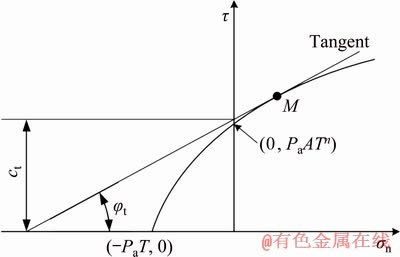
Fig. 1 Strength curve of nonlinear Baker failure criterion and its tangent
For a point M along the curve, the tangent equation is [62]:
��=ct+��ntan ��t (3)
where ct is the cohesive force at tangent point; ��t is the internal friction angle at tangent point; the values of ct and tan ��t are the intercept and slope of the tangential line, respectively.
According to the tangent technique [27,62,63], the relationship between nonlinear parameters A, n, and T is derived as follows:
From Fig. 1 and Eq. (2), we have
 (4)
(4)
Equation (4) can be reformulated into
 (5)
(5)
Substituting Eq. (5) into Eq. (2) yields
 (6)
(6)
Substituting Eq. (5) and Eq. (6) into Eq. (3) yields
 (7)
(7)
Equation (7) represents the relationship of the nonlinear parameters A, n and T, and it is based on the nonlinear Baker failure criterion.
3 3D Terzaghi failure mode and surrounding rock pressure
3.1 3D Terzaghi failure mode
A failure mode with a kinematically admissible velocity field is essential to limit analysis. In this study, according to the 2D failure mode (Fig. 2(a)), a new 3D Terzaghi failure mode (Fig. 2(b)) was established by a rotation method. The rectangle EFF1E1 in 2D failure mode (Fig. 2(a)) becomes cylinder EE2E1E3FF2F1F3 in 3D failure mode (Fig. 2(b)), block FMN or F1M1N1 is transformed into hollow circular truncated cone FF2F1F3MM2M1M3NN2N1N3, and cavity MM1N1N is transformed into cylinder MM2M1M3NN2N1N3. The new 3D failure mode consists of a rigid cylinder block EE2E1E3FF2F1F3 and a shear hollow circular truncated cone FF2F1F3MM2M1M3NN2N1N3. The velocity discontinuous lines EF (or E1F1), FM (or F1M1) and FN(or F1N1) in 2D failure mode (Fig. 2(a)) are converted into the cylindrical surface EE2E1E3FF2F1F3, the circular conical surface FF2F1F3MM2M1M3 and the anchor ring FF2F1F3NN2N1N3 in 3D failure mode (Fig. 2(b)), respectively. The rigid cylinder block EE2E1E3FF2F1F3 slips down at the velocity of v0. The angle between the velocity v0 and the velocity discontinuities surface EE2E1E3FF2F1F3 is 0��. The angle between the velocity v1 and the velocity discontinuities surface FF2F1F3MM2M1M3 is jt. The relative velocity v01 is for the discontinuities of FF2F1F3NN2N1N3. The angle between the FF2F1F3NN2N1N3 and its relative velocity v01 is jt. The supporting forces of the roof and sidewall of the cavity are assumed to be uniformly distributed. The cavity height, width and buried depth are h, 2a and H, respectively. The supporting forces at the top of the cavity and the sidewalls are q and e, respectively. Their relationship is e=Kq, where K is the lateral pressure coefficient. The associated flow rule, velocity boundary conditions, and compatibility conditions are met in the formulations [56]. Besides, the velocity meets the condition of vector closure and the velocity field is illustrated in Fig. 2(c), where �� is the failure angle.
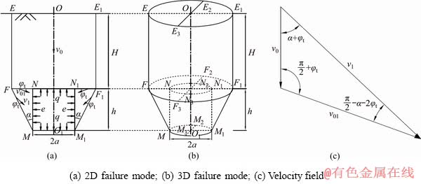
Fig. 2 Failure mode of underground cavity and associated velocity field
From Fig. 2(c), the velocity relationship is
 (8)
(8)
3.2 Surrounding rock pressure
According to the upper bound theorem of limit analysis (Eq. (1)), the limit load can be determined when the work rate of external force equals the internal energy dissipation. The limit load calculated from the approach is considered as the limit surrounding rock pressure in this work. The work rate of external force includes the work rate generated by the geo-material self-weight (rigid cylinder block EE2E1E3FF2F1F3 and hollow circular truncated cone FF2F1F3MM2M1M3NN2N1N3) and the supporting reaction forces (q and e). The internal energy dissipation is generated by the cohesive force of surrounding rock. The internal energy is dissipated along discontinuous surfaces (cylindrical surface EE2E1E3FF2F1F3, circular conical surface FF2F1F3MM2M1M3 and anchor ring FF2F1F3NN2N1N3).
(1) External rate of work
The external rate of work consists of the rate of self-weight Ww and the rate of supporting force WT.
The work rate of self-weight, Ww, is derived through multiplying the united weight of the rock mass by the detachment volume and the slip velocity:
 (9)
(9)
where f1=(a/h+tan ��)2, f2=tan ����(3a/h+tan ��)�� ; �� is the unit weight of rocks.
The work rates of reaction forces WT are formulated by the vertical supporting force q of the top of the cavity and the horizontal supporting force e on the side of the cavity. Because the support reaction force is negative, the support reaction force rate is negative.
WT=-��qh2v0f3 (10)
where  .
.
Combining Eq. (9) and Eq. (10) leads to the total external rate of work:
 (11)
(11)
where Wext is the total external rate of work.
(2) Internal energy dissipation
The internal energy dissipation (Wint) on the velocity discontinuity surface is a multiple of the cohesive force and the velocity:
Wint=ct��h2v0(f4+f5+f6) (12)
where 
(3) Surrounding rock pressure
According to the virtual power principle, the external rate of work (i.e., Eq. (11)) is equal to the internal energy dissipation (i.e., Eq. (12)). Thus, the upper bound surrounding rock pressure can be derived:
 (13)
(13)
(4) Constraint condition
According to Fig. 2(c), the velocity constraint is presented as
 (14)
(14)
The upper bound solution of the surrounding rock pressure can be derived from Eq. (13) under the constraint in Eq. (14). All calculations are performed by the optimization toolbox in the Matlab software.
4 Numerical study
4.1 Failure mode validation
The FLAC3D software was utilized here for numerical modelling. The surrounding rock parameters are found in Ref. [38], which are shown in Table 1. The dimension of the model is 60 m �� 60 m �� 60 m (x �� y �� z), the height and width (or length) of the cavity are 10 m and the depth of cover is 20 m, as shown in Fig. 3. The mesh type is the cylindrical circular radial mesh. The boundary conditions are that the top surface is set to be free and the rest surfaces are fixed. The cohesive-frictional Mohr-Coulomb law is applied to the surrounding rock. The elastic modulus and Poisson ratio are 20 GPa and 0.3, respectively. The results of the 3D displacement field and the contour of the maximum shear strain increment, Figs. 4 and 5, are used to show the failure mode of the surrounding rock.
From Fig. 4, it is clear that a triangular region appears on the cavity side, which is consistent with the assumed failure mode in this study (Fig. 2(b)).
Table 1 Physical and mechanical parameters in analyses
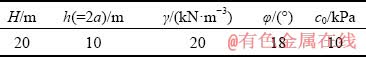
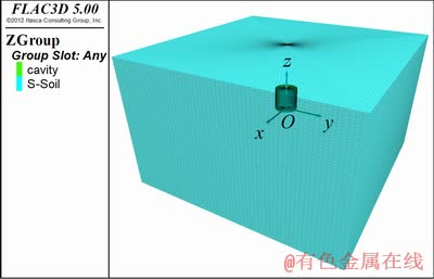
Fig. 3 FLAC3D numerical model of underground cavity
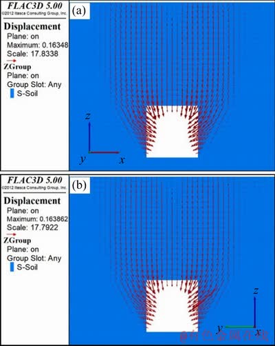
Fig. 4 Displacement field along xz (a) and yz (b) profiles

Fig. 5 Contours of maximum shear strain increment along xz (a) and yz (b) profiles
In Fig. 4, a failure cylindrical area is formed at the top of the cavity, which is also consistent with the assumed failure mode (Fig. 2(b)). The observations can also be found in Fig. 5. Therefore, the numerical results validate the failure mode in this work. Furthermore, the failure mode is consistent with the finite element upper bound method in Ref. [38].
The upper bound method of limit analysis is used to calculate the ultimate load and velocity field at the limit state (plastic flow state). For comparison, the displacement field of FLAC3D at the final stage is drawn. A good agreement has been found between Fig. 2(c) and Fig. 4, indicating that the velocity field assumed in this work is reasonable.
4.2 Quantitative analysis and method validation
To validate the approach, the 3D results are compared with the analytical solutions of Terzaghi theory [64] and the results in Ref. [38]. Numerical results of the surrounding rock pressure calculated by the 2D and 3D failure modes are compared. In addition, in the 3D failure mode, the upper bound solutions of surrounding rock pressure calculated by the Mohr-Coulomb failure criterion and nonlinear Baker failure criterion are compared. The same parameters in Ref. [38], as listed in Table 1, are used.
According to the Terzaghi ground pressure theory [64], the surrounding rock pressure q is
 (15)
(15)
The lateral pressure coefficient K is varied from 0.6 to 1.5. The numerical results are summarized in Fig. 6. Figure 6(a) shows that in the 2D failure mode, the results obtained by nonlinear Baker failure criterion are in a good agreement with results in Ref. [38]. The Terzaghi method underestimates the surrounding rock pressure, indicating its results for support design may lead to unsafe conditions.
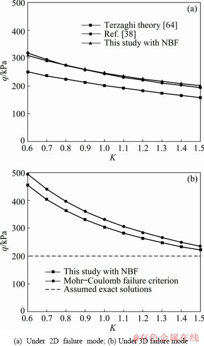
Fig. 6 Variation of surrounding rock pressure q with lateral pressure coefficient K by Terzaghi theory [64], method in Ref. [38] and this study (NBF: Nonlinear Baker failure criterion)
In Fig. 6(b), the exact solution below the upper bound solution is assumed to be the dotted line. The figure shows that under the 3D failure mode, the results obtained by the nonlinear Baker failure criterion are closer to the assumed exact solution than those obtained by the Mohr-Coulomb failure criterion. Thus, these solutions obtained by the nonlinear Baker failure criterion are more accurate.
4.3 Parameter studies
The parameters in the nonlinear Baker failure criterion, i.e., scale parameter A, curvature parameter n and shift parameter T have clear physical meaning. A controls the magnitude of shear strength; n controls the curvature of the envelope; T controls the location of the envelope on the stress (��n) axis representing a non-dimensional tensile strength [52,53]. In this section, the proposed approach is used to study the influence of key parameters on the surrounding rock pressure of underground cavities and failure ranges. The numerical bounds of parameters are determined from Refs. [52,53]. The parametric study results are educational to engineers. When the geological parameters change, engineers can have a quick estimate of the surrounding rock pressure. In the following chapters, all the lateral pressure coefficients K are not grater than 1.
4.3.1 Effect of A on q
To study the influence of scale parameter A on the surrounding rock pressure q, a series of studies are performed, in which A is set to be 0.5-0.9, n is set to be 0.7, T is set to be 0.2, and K is set to be 0.6-1.0. The results are shown in Fig. 7.
It can be seen from Figs. 7(a) and (b) that the surrounding rock pressure decreases with the increase of A. When A increases, the slope (q/A) of the curve of surrounding rock pressure q vs A decreases, as shown in Fig. 7(c). The effect of A on the surrounding rock pressure is influenced by the lateral pressure coefficient K. The decrease in lateral pressure coefficient K enhances the sensitivity of scale parameter A on the surrounding rock pressure, as shown by the dotted lines in Figs. 7(a) and (b).
4.3.2 Effect of n on q
To study the influence of curvature parameter n on the surrounding rock pressure q, a series of studies are conducted with the curvature parameter n of 0.5-0.9, scale parameter A of 0.5, shift parameter T of 0.2 and lateral pressure parameter K of 0.6-1.0. The results are shown in Fig. 8.
Figures 8(a) and (b) show that the surrounding rock pressure decreases with the increase of curvature parameter n. When curvature parameter n increases, the slope (q/n) decreases, as shown in Fig. 8(c). The larger curvature coefficient n results in a smaller influence on the surrounding rock pressure q. The effect of curvature coefficient n on the surrounding rock pressure q is also influenced by lateral pressure coefficient K. The decrease in lateral pressure coefficient K reduces the influence of curvature coefficient n on the surrounding rock pressure q, as shown by the dotted lines in Figs. 8(a) and (b).
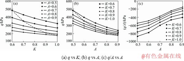
Fig. 7 Effect of A on surrounding rock pressure q

Fig. 8 Effect of curvature parameter n on surrounding rock pressure q
4.3.3 Effect of T on q
To study the influence of shift parameter T on the surrounding rock pressure, the following parameters are used including T of 0-0.8, scale parameter A of 0.5, curvature coefficient n of 0.7 and lateral pressure coefficient K of 0.6-1.0. The results are shown in Fig. 9.
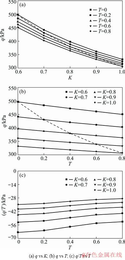
Fig. 9 Effect of shift parameter T on surrounding rock pressure q
It can be seen from Figs. 9(a) and (b) that the surrounding rock pressure q decreases with the increase in shift parameter T. When shift parameter T increases, the slope (q/T) decreases. Figure 9(c) proves that the larger shift parameter T leads to a less sensitive effect on the surrounding rock pressure. In addition, the influence of shift parameter T on the surrounding rock pressure is affected by lateral pressure coefficient K. The decrease of lateral pressure coefficient K improves the influence of the shift parameter T on the surrounding rock pressure q, as shown in the dotted lines in Figs. 9(a) and (b).
4.3.4 Failure range angle
As indicated in Fig. 2, when the failure angle �� is determined, the failure range of the surrounding rock can be calculated. Determining the surrounding rock pressure and the corresponding ultimate failure angle �� is convenient with the proposed approach as problems are solved with the available optimization toolbox in the Matlab. The influence of different parameters on the failure angle �� is derived through the parametric analysis, as shown in Fig. 10.

Fig. 10 Effects of different parameters on failure angle ��
All parameters (scale parameter A, curvature parameter n, shift parameter T and lateral pressure coefficient K) have significant effects on the failure range. The failure angle �� decreases with the increase of the four individual parameters. Furthermore, it can be seen that the scale parameter A has the most obvious effect on the angle ��, followed by the curvature parameter n, the shift parameter T and lateral pressure coefficient K. From an engineering perspective, the surrounding rock with larger scale parameter A, curvature parameter n, shift parameter T, and lateral pressure coefficient K tends to contract the potential failure range.
The results of the failure range corresponding to four cases of Fig. 10 are shown in Fig. 11. The influence of these parameters on the failure ranges can be demonstrated.
5 Conclusions
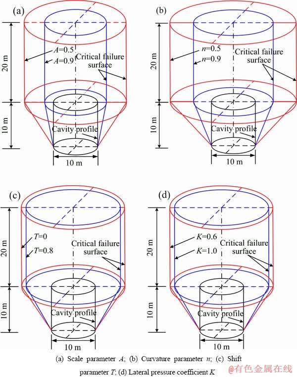
Fig. 11 Four failure results with varied parameters
(1) The surrounding rock pressure calculated by the upper bound method of limit analysis is safer than that calculated by the Terzaghi theory. The numerical results show that the surrounding rock pressure in the 3D failure mode is larger than that in the 2D mode.
(2) The nonlinear Baker failure criterion used in this work can provide more accurate solutions than the Mohr-Coulomb failure criterion.
(3) The surrounding rock pressure decreases with the increase of scale parameter A, curvature parameter n, shift parameter T and lateral pressure coefficient K.
(4) The surrounding rock with large scale parameter A, curvature parameter n, shift parameter T and lateral pressure coefficient K (K��1) tends to improve the stability of underground cavities.
References
[1] SMITH C, GILBERT M. Application of discontinuity layout optimization to plane plasticity problems [J]. Proceedings of the Royal Society A: Mathematical, Physical and Engineering Sciences, 2007, 463(2086): 2461-2484.
[2] GILBERT M, SMITH C C, HASLAM I, PRITCHARD T. Application of discontinuity layout optimization to geotechnical limit analysis problems [C]//Proc 7th Eur Conf Num Meths Geo Eng. Trondheim, Norway, 2010: 169-174.
[3] HAWKSBEE S, SMITH C, GILBERT M. Application of discontinuity layout optimization to three-dimensional plasticity problems [J]. Proceedings of the Royal Society A: Mathematical, Physical and Engineering Sciences, 2013, 469(2155): 1-18.
[4] LEE K M, ROWE R K. Finite element modelling of the three-dimensional ground deformations due to tunnelling in soft cohesive soils: Part I��Method of analysis [J]. Computers and Geotechnics, 1990, 10(2): 87-109.
[5] ZHANG Chun-yang, PU Cheng-zhi, CAO Ri-hong, JIANG Ting-ting, HUANG Gang. The stability and roof-support optimization of roadways passing through unfavorable geological bodies using advanced detection and monitoring methods, among others, in the Sanmenxia Bauxite Mine in China��s Henan Province [J]. Bulletin of Engineering Geology and the Environment, 2019, 78(7): 5087-5099.
[6] KASPER T, MESCHKE G. A 3D finite element simulation model for TBM tunnelling in soft ground [J]. International Journal for Numerical and Analytical Methods in Geomechanics, 2004, 28(14): 1441-1460.
[7] WANG H N, ZENG G S, JIANG M J. Analytical stress and displacement around non-circular tunnels in semi-infinite ground [J]. Applied Mathematical Modelling, 2018, 63: 303-328.
[8] WANG Y X, SHAN S B, ZHANG C, GUO P P. Seismic response of tunnel lining structure in a thick expansive soil stratum [J]. Tunnelling and Underground Space Technology, 2019, 88: 250-259.
[9] MENG Jing-jing, CAO Ping, HUANG Jin-song, LIN Hang, CHEN Yu, CAO Ri-hong. Second-order cone programming formulation of discontinuous deformation analysis [J]. International Journal for Numerical Methods in Engineering, 2019, 118(5): 243-257.
[10] PORTIOLI F, CASAPULLA C, CASCINI L. An efficient solution procedure for crushing failure in 3D limit analysis of masonry block structures with non-associative frictional joints [J]. International Journal of Solids and Structures, 2015, 69: 252-266.
[11] PORTIOLI F P A. Rigid block modelling of historic masonry structures using mathematical programming: A unified formulation for non-linear time history, static pushover and limit equilibrium analysis [J]. Bulletin of Earthquake Engineering, 2020, 18: 211-239.
[12] LI Ze, ZHOU Yu, GUO Ya-kun. Upper-bound analysis for stone retaining wall slope based on mixed numerical discretization [J]. International Journal of Geomechanics, 2018, 18(10): 04018122.
[13] UKRITCHON B, KEAWSAWASVONG S. Stability of retained soils behind underground walls with an opening using lower bound limit analysis and second-order cone programming [J]. Geotechnical and Geological Engineering, 2019, 37(3): 1609-1625.
[14] JIANG Quan, FENG Xia-ting, FAN Yi-lin, FAN Qi-xiang, LIU Guo-feng, PEI Shu-feng, DUAN Shu-qian. In situ experimental investigation of basalt spalling in a large underground powerhouse cavern [J]. Tunnelling and Underground Space Technology, 2017, 68: 82-94.
[15] LEI Ming-feng, PENG Li-min, SHI Cheng-hua. Calculation of the surrounding rock pressure on a shallow buried tunnel using linear and nonlinear failure criteria [J]. Automation in Construction, 2014, 37: 191-195.
[16] ZHAO Yan-lin, WANG Yi-xian, WANG Wei-jun, TANG Jin-zhou. Modeling of non-linear rheological behavior of hard rock using triaxial rheological experiment [J]. International Journal of Rock Mechanics and Mining Sciences, 2017, 93: 66-75.
[17] LI Zhuo, RAO Qiu-hua, LI Peng, YI Wei. Crack initiation rate of brittle rock under thermal-hydro-mechanical coupling condition [J]. Transactions of Nonferrous Metals Society of China, 2018, 28(10): 2107-2113.
[18] YI Wei, RAO Qiu-hua, LI Zhuo, SHEN, Qing-qing. A new measurement method of crack propagation rate for brittle rock under THMC coupling condition [J]. Transactions of Nonferrous Metals Society of China, 2019, 29(8): 1728-1736.
[19] LI Xi-bing, CHEN Zheng-hong, WENG Lei, LI Chong-jin. Unloading responses of pre-flawed rock specimens under different unloading rates [J]. Transactions of Nonferrous Metals Society of China, 2019, 29(7): 1516-1526.
[20] HU Jian-hua, YANG Dong-jie. Meso-damage evolution and mechanical characteristics of low-porosity sedimentary rocks under uniaxial compression [J]. Transactions of Nonferrous Metals Society of China, 2020, 30(4): 1071-1077.
[21] ZHOU Zi-long, ZHOU Jing, CAI Xin, RUI Yi-chao, CHEN Lian-jun, WANG Hai-quan. Acoustic emission source location considering refraction in layered media with cylindrical surface [J]. Transactions of Nonferrous Metals Society of China, 2020, 30(3): 789-799.
[22] WANG Fei, CAO Ping, WANG Yi-xian, HAO Rui-qing, MENG Jing-jing, SHANG Jun-long. Combined effects of cyclic load and temperature fluctuation on the mechanical behavior of porous sandstones [J]. Engineering Geology, 2020, 266: 105466.
[23] DUAN Kang, JI Yin-lin, XU Nu-wen, WAN Zhi-jun, WU Wei. Excavation-induced fault instability: Possible causes and implications for seismicity [J]. Tunnelling and Underground Space Technology, 2019, 92: 103041.
[24] PARK S H, ADACHI T. Laboratory model tests and FE analyses on tunneling in the unconsolidated ground with inclined layers [J]. Tunnelling and underground space technology, 2002, 17(2): 181-193.
[25] CHU B L, HSU S C, CHANG Y L, LIN Y S. Mechanical behavior of a twin-tunnel in multi-layered formations [J]. Tunnelling and Underground Space Technology, 2007, 22(3): 351-362.
[26] QIN C B, CHIAN S C, YANG X L, DU D C. 2D and 3D limit analysis of progressive collapse mechanism for deep-buried tunnels under the condition of varying water table [J]. International Journal of Rock Mechanics and Mining Sciences, 2015, 80: 255-264.
[27] ZHANG Dao-bing, MA Zong-yu, YU Biao, YIN Hua-dong. Upper bound solution of surrounding rock pressure of shallow tunnel under nonlinear failure criterion [J]. Journal of Central South University, 2019, 26(7):1696-1705.
[28] LI Tian-zheng, YANG Xiao-li. 3D rotational failure mechanism of tunnel face in weathered and saturated Hoek-Brown rock masses [J]. KSCE Journal of Civil Engineering, 2019, 23(6): 2723-2732.
[29] WILSON D W, ABBO A J, SLOAN S W, YAMAMOTO K. Undrained stability of rectangular tunnels where shear strength increases linearly with depth [J]. Canadian Geotechnical Journal, 2017, 54(4): 469-480.
[30] WANG Yi-xian, GUO Pan-pan, DAI Feng, LI Xian. Behavior and modeling of fiber-reinforced clay under triaxial compression by combining the superposition method with the energy-based homogenization technique [J]. International Journal of Geomechanics, 2018, 18(12): 04018172.
[31] LIN Luo-bing, CHEN Fu-quan, HUANG Zeng. An analytical solution for sectional estimation of stress and displacement fields around a shallow tunnel [J]. Applied Mathematical Modelling, 2019, 69: 181-200.
[32] ZHANG Rui, XIAO Yao, ZHAO Ming-hua, ZHAO Heng. Stability of dual circular tunnels in a rock mass subjected to surcharge loading [J]. Computers and Geotechnics, 2019, 108: 257-268.
[33] LECA E, DORMIEUX L. Upper and lower bound solutions for the face stability of shallow circular tunnels in frictional material [J]. Geotechnique, 1990, 40(4): 581-606.
[34] BOLTON M D, LAU C K. Vertical bearing capacity factors for circular and strip footings on Mohr-Coulomb soil [J]. Canadian Geotechnical Journal, 1993, 30(6): 1024-1033.
[35] SLOAN S W, KLEEMAN P W. Upper bound limit analysis using discontinuous velocity fields [J]. Computer Methods in Applied Mechanics and Engineering, 1995, 127(1-4): 293-314.
[36] ULRITCHON B, WHITTLE A J, SLOAN S W. Undrained limit analyses for combined loading of strip footings on clay [J]. Journal of Geotechnical and Geoenvironmental Engineering, 1998, 124(3): 265-276.
[37] MICHALOWSKI R L. Upper-bound load estimates on square and rectangular footings [J]. Geotechnique, 2001, 51(9): 787-798.
[38] YANG Feng, YANG Jun-sheng. Stability of shallow tunnel using rigid blocks and finite-element upper bound solutions [J]. International Journal of Geomechanics, 2010, 10(6): 242-247.
[39] HOEK E, BROWN E T. Empirical strength criterion for rock masses [J]. Journal of Geotechnical and Geoenvironmental Engineering, 1980, 106(GT9): 1013-1035.
[40] HOEK E. Strength of jointed rock masses [J]. Geotechnique, 1983, 33(3): 187-223.
[41] AGAR J G, MORGENSTERN N R, SCOTT J D. Shear strength and stress-strain behaviour of Athabasca oil sand at elevated temperatures and pressures [J]. Canadian Geotechnical Journal, 1987, 24(1): 1-10.
[42] CARRANZA-TORRES C, FAIRHURST C. The elasto- plastic response of underground excavations in rock masses that satisfy the Hoek-Brown failure criterion [J]. International Journal of Rock Mechanics and Mining Sciences, 1999, 36(6): 777-809.
[43] CARRANZA-TORRES C. Elasto-plastic solution of tunnel problems using the generalized form of the Hoek-Brown failure criterion [J]. International Journal of Rock Mechanics and Mining Sciences, 2004, 41(S): s1-s11.
[44] FRALDI M, GUARRACINO F. Limit analysis of collapse mechanisms in cavities and tunnels according to the Hoek�CBrown failure criterion [J]. International Journal of Rock Mechanics and Mining Sciences, 2009, 46(4): 665-673.
[45] YANG Xiao-li, HUANG Fu. Collapse mechanism of shallow tunnel based on nonlinear Hoek�CBrown failure criterion [J]. Tunnelling and Underground Space Technology, 2011, 26(6): 686-691.
[46] SENENT S, MOLLON G, JIMENEZ R. Tunnel face stability in heavily fractured rock masses that follow the Hoek�CBrown failure criterion [J]. International Journal of Rock Mechanics and Mining Sciences, 2013, 60: 440-451.
[47] UKRITCHON B, KEAWSAWASVONG S. Stability of unlined square tunnels in Hoek-Brown rock masses based on lower bound analysis [J]. Computers and Geotechnics, 2019, 105: 249-264.
[48] KLAR A, OSMAN A S, BOLTON M. 2D and 3D upper bound solutions for tunnel excavation using ��elastic�� flow fields [J]. International Journal for Numerical and Analytical Methods in Geomechanics, 2007, 31(12): 1367-1374.
[49] MOLLON G, DIAS D, SOUBRA A H. Face stability analysis of circular tunnels driven by a pressurized shield [J]. Journal of Geotechnical and Geoenvironmental Engineering, 2010, 136(1): 215-229.
[50] YANG Xiao-li, HUANG Fu. Three-dimensional failure mechanism of a rectangular cavity in a Hoek�CBrown rock medium [J]. International Journal of Rock Mechanics and Mining Sciences, 2013, 61: 189-195.
[51] PAN Q J, DIAS D. Three dimensional face stability of a tunnel in weak rock masses subjected to seepage forces [J]. Tunnelling and Underground Space Technology, 2018, 71: 555-566.
[52] BAKER R. Nonlinear Mohr envelopes based on triaxial data [J]. Journal of geotechnical and geoenvironmental engineering, 2004, 130(5): 498-506.
[53] JIANG J C, BAKER R, YAMAGAMI T. The effect of strength envelope nonlinearity on slope stability computations [J]. Canadian Geotechnical Journal, 2003, 40(2): 308-325.
[54] MICHALOWSKI R L, DRESCHER A. Three-dimensional stability of slopes and excavations [J]. Geotechnique, 2009, 59(10): 839-850.
[55] LI Y X, YANG X L. Soil-slope stability considering effect of soil-strength nonlinearity [J]. International Journal of Geomechanics, 2019, 19(3): 04018201.
[56] LI Zheng-wei, YANG Xiao-li. Active earth thrust considering tension crack, pore-water pressure and soil nonlinearity [J]. KSCE Journal of Civil Engineering, 2019, 23(1): 56-62.
[57] DRUCKER D C, PRAGER W, GREENBERG H J. Extended limit design theorems for continuous media [J]. Quarterly of Applied Mathematics, 1952, 9(4): 381-389.
[58] CHEN W F. Limit analysis and soil plasticity [M]. Amsterdam: Elsevier, 2013.
[59] de MELLO V F B. Reflections on design decisions of practical significance to embankment dams [J]. Geotechnique, 1977, 27(3): 281-355.
[60] CHARLES J A, WATTS K S. The influence of confining pressure on the shear strength of compacted rockfill [J]. Geotechnique, 1980, 30(4): 353-367.
[61] CHARLES J A, SOARES M M. The stability of slopes in soils with nonlinear failure envelopes [J]. Canadian Geotechnical Journal, 1984, 21(3): 397-406.
[62] ZHANG Jia-hua, XU Jing-shu, ZHANG Biao. Energy analysis of stability of twin shallow tunnels based on nonlinear failure criterion [J]. Journal of Central South University, 2014, 21(12): 4669-4676.
[63] YANG Xiao-li, YIN Jian-hua. Estimation of seismic passive earth pressures with nonlinear failure criterion [J]. Engineering Structures, 2006, 28(3): 342-348.
[64] YANG Xiao-li, WANG Zuo-wei. Limit analysis of earth pressure on shallow tunnel using nonlinear failure criterion [J]. Journal of Central South University (Science and Technology), 2010, 41(1): 299-302. (in Chinese).
���ڷ�����Baker�ƻ���ĵ���������ά��������
������1���� ƽ1���� ��1���Ͼ���2��������3
1. ���ϴ�ѧ ��Դ�밲ȫ����ѧԺ����ɳ 410083��
2. Department of Civil, Environmental and Natural Resources Engineering, Lulea University of Technology, Lulea, Sweden��
3. �Ϸʹ�ҵ��ѧ ��ľ����ѧԺ���Ϸ� 230009
ժ Ҫ�������������Baker�ƻ������������������ϣ��о���������Χ���ȶ��ԡ�ͨ����չ�������Ҷ�ά�ƻ�ģʽ������һ����ά�ƻ�ģʽ�����ڽ�������ά�ƻ�ģʽ������Χ��ѹ�����ޱ���ʽ���ڷ����߶Ȳ��������ʲ�����λ�ò����Ͳ�ѹϵ����Χ��ѹ����Ӱ��ǰ��ͨ��һϵ��ʵ����֤�÷�������Ч�ԡ������о������ȷ���������ҵ��ƻ���Χ���õ����½��ۣ�(1)���ñ�������ķ���Ԥ���Χ��ѹ���Ȼ���Mohr-Coulomb�ƻ���Ԥ���Χ��ѹ������ȷ��(2)�߶Ȳ��������ʲ�����λ�ò����Ͳ�ѹϵ��Խ��Χ��Խ�ȶ���(3)�����������Ԥ����άģ�͵��ƻ���Χ��
�ؼ��ʣ�Baker�ƻ��������ң�Χ��ѹ������ά�ƻ�ģʽ����������
(Edited by Wei-ping CHEN)
Foundation item: Projects (51679117, 11772358, 51774322, 51474249, 51404179, 51274249) supported by the National Natural Science Foundation of China
Corresponding author: Jing-jing MENG; Tel: +46-920-492488; E-mail: jingjing.meng@ltu.se
DOI: 10.1016/S1003-6326(20)65350-X
Abstract: A generalized nonlinear Baker failure criterion is employed with the upper bound limit analysis to study the surrounding rock stability of underground cavities. A three-dimensional (3D) failure mode is established by extending the two-dimensional (2D) failure mode, which offers an upper bound expression of the surrounding rock pressure. This method is validated with a series of examples before the influence of four parameters of scale parameter, curvature parameter, shift parameter and lateral pressure coefficient, on the surrounding rock pressure is analyzed. According to these results, failure ranges of the underground cavities are determined. The following conclusions are reached: (1) the proposed approach is more accurate to predict surrounding rock pressure than the Mohr-Coulomb failure criterion; (2) the surrounding rock with large scale parameter, curvature parameter, shift parameter, and lateral pressure coefficient can lead to a more stable underground cavity; (3) the failure range in 3D mode can be predicted according to the upper bound solutions.
