

![]()

Trans. Nonferrous Met. Soc. China 22(2012) 398-403
Temperature and stress fields in electron beam welded Ti-15-3 alloy to 304 stainless steel joint with copper interlayer sheet
ZHANG Bing-gang, WANG Ting, DUAN Xiao-hui, CHEN Guo-qing, FENG Ji-cai
State Key Laboratory of Advanced Welding and Joining, Harbin Institute of Technology, Harbin 150001, China
Received 21 July 2011; accepted 8 October 2011
Abstract:
Electron beam welding of Ti-15-3 alloy to 304 stainless steel (STS) using a copper filler metal was carried out. The temperature fields and stress distributions in the Ti/Fe and Ti/Cu/Fe joint during the welding process were numerically simulated and experimentally measured. The results show that the rotated parabola body heat source is fit for the simulation of the electron beam welding. The temperature distribution is asymmetric along the weld center and the temperature in the titanium alloy plate is higher than that in the 304 STS plate. The thermal stress also appears to be in asymmetric distribution. The residual tensile stress mainly exists in the weld at the 304 STS side. The copper filler metal decreases the peak temperature and temperature grade in the joint as well as the residual stress. The longitudinal and lateral residual tensile strengths reduce by 66 MPa and 31 MPa, respectively. From the temperature and residual stress, it is concluded that copper is a good filler metal candidate for the electron beam welding of Ti-15-3 titanium alloy to 304 stainless steel.
Key words:
Ti-15-3 alloy; 304 stainless steel; electron beam welding; temperature field; residual stress;
1 Introduction
It has been generally acknowledged that the use of titanium alloy as a structural material has been increased significantly. Titanium alloy has good features such as high specific strength, good stiffness, good high temperature mechanical properties and oxidation resistance with potential applications in aeronautics and astronautics industries for both military and civil purposes [1]. While stainless steel is a common material with low cost in most industry fields [2]. Composite components of titanium alloy and steel can fully exert the advantages of these two materials simultaneously. Fusion welding of titanium alloy and steel was difficult to implement for the production of brittle phases in the weld [3, 4]. Research work of TIG welding of pure titanium and pure iron showed that the basic reason for the embrittlement of the joint was the emergence of continuously distributed TiFe, TiFe2 and eutectic structure. Hardness of the weld metal was in the range of HV740-HV1324 [5]. Inversely, pressure welding can eliminate the problems in the fusion welding because the base metals remain in the solid state during joining and many successful examples have been reported [6-9]. However, during the diffusion bonding process, the whole metallic materials of the specimens will be heated to the elevated temperature, which is not permitted in some occasions. In addition, the diffusion process needs a long time to implement in general.
Owing to the advantages of high energy density, precisely controllable heating position and radius, electron beam welding was the most frequently utilized fusion welding method in the field of joining dissimilar metals [10-13]. In this way, only a small heat affected zone can be produced and the process can be finished in a shorter period. WANG et al [14] have tried to join TA15 titanium alloy and 304 stainless steel by electron beam welding. The joint cracked after welding for the brittleness induced by the continuously distributed Ti-Fe intermetallics with Vicker��s hardness higher than HV1000. Whereas, another attempt to join Ti-15-3 to 304 stainless steel by electron beam welding with a copper interlayer sheet has succeeded. A large amount of Ti-Fe-Cu ternary intermetallic blocks and some Ti-Cu intermetallics were formed at the interface between titanium alloy and the weld in the joint. The Vicker��s hardness of the interface only reached HV700, which indicated that the brittleness of the joint was weakened. As a result, a tensile strength of 234 MP was obtained [15]. The above literatures just discussed one factor for the craking �� brittleness of the joint dependent on the microstructure. In fact, thermal stress was another wondrously important factor, especially for the dissimilar metal joint. ALEMAN et al [16] reported that the factor for the crack formation during diffusion bonding of titanium alloy to stainless steel was the large internal stress due to the difference of linear expansion and heat transmission coefficient between titanium and steel. However, almost no published literature on the thermal stress in the electron beam welded titanium alloy to stainless steel joint was reported. Specially, the influence of the soft copper interlayer sheet on the thermal stress in the joint was not discussed before. In this work, the temperatures and residual stresses of the Ti/Fe and Ti/Cu/Fe joint were numerically simulated and experimentally measured. Consequently, the stress factor for the crack free electron beam welded Ti-15-3 to 304 stainless steel joint with the assistance of copper interlayer sheet was summarized.
2 Finite element modeling
2.1 Finite element model
In this simulation, a three-dimensional finite element model for thermo-mechanical coupled analysis was developed using commercial ANSYS software. The dimensions of the two plates were both 55 mm��25 mm�� 2.5 mm. The two plates were connected by the ��VGLUE�� command, so that the areas, lines, and keypoints at the common volume boundaries were merged. ��Solid 70�� element type was used to mesh the entity models to construct the finite element model. For the ultra-high energy intensity of the electron beam, the temperature grades were very large in the weld zone and the heat affected zone. So, the small meshes were used in these zones. But in the regions far from the weld, the larger meshes were selected because of the approximately uniform temperature field. This meshing method can improve the calculating efficiency significantly. Figure 1 shows the finite element model of the titanium alloy and 304 stainless steel plates. For the finite element model of the Ti/Cu/Fe joint, a 1 mm-thick copper interlayer model was added to the center of the Ti/Fe joint model by APDL operation of the ANSYS software.
2.2 Heat transfer governing equation and heat source model
The heat transfer governing equation for the dissimilar metal joints in a moving coordinate system with a positive x-direction moving electron beam can be where x, y, z are the Cartesian coordinates; �� is the density of the material; cp is the specific heat capacity; k is the heat conductivity; T is the transient temperature; ![]() is the heat source intensity in the material.
is the heat source intensity in the material.
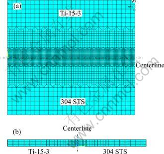
Fig. 1 Finite element model of Ti/Fe joint: (a) Top surfaces; (b) Cross section
written as:
![]() (1)
(1)
According to the shape feature of the electron beam weld and the ��keyhole effect��, a rotated parabola body heat source model was developed as shown in Fig. 2. Assuming that the heat flux is a Gaussian distribution centered on the electron beam at any horizontal section of the heat source model, the heat distribution at any point A can be written as:
![]() (3)
(3)
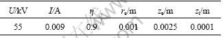
where �� is the heat efficiency of electron beam welding; U is the accelerating voltage; I is the beam current; e is the Euler��s constant(approximately 2.7183); re is the radius of the top surface; r0 is the radius of the horizontal section containing point A; r is the distance from the point A to the center of the horizontal section; z is the Cartesian coordinate; zi and ze are the z coordinates of the bottom and the top surfaces. The values of the calculating parameters used in this simulation are listed in Table 1.
The analysis of welding temperature field is a typical nonlinear transient heat conduction problem. ANSYS can accurately solve the nonlinear transient heat conduction problem by the finite difference method and the iterative method. The movement of the heat source along the welding direction was realized by the ANASYS program.

Fig. 2 Schematic diagram of heat source model
Table 1 Calculating parameters used in this simulation
2.3 Initial and boundary conditions
For the welding temperature calculation, the following conditions are assumed: 1) The materials are isotropic continuum; 2) Welding is a quasi-steady process; 3) The initial temperature is 20 ��C; 4) The welding pool flow is omitted; 5) Only the radiation is considered and the radiant heat transfer intensity q is expressed as Eq. (4) according to Stephen-Boltzmann law:
![]() (4)
(4)
where �� is the Stephen-Boltzmann constant (5.67 W/(cm2![]() K4)); �� is the emissivity of the specimen surface; T is the temperature of specimen surface; Ta is the temperature of the surrounding atmosphere.
K4)); �� is the emissivity of the specimen surface; T is the temperature of specimen surface; Ta is the temperature of the surrounding atmosphere.
The thermal stress was calculated with the thermal elastoplastic theory and the thermo-mechanical coupled analysis. So the following conditions are assumed:
1) The materials are isotropic; 2) The yield conditions obey the Mises yield criterion; 3) Mechanical behaviors of the materials in the plastic range obey the plastic flow rule; 4) Elastic strain, plastic stain and thermal strain are indiscriminate; 5) The strain changes linearly for the small increments; 6) The strains of the three head faces perpendicular to each other along the x, y, z coordinate axes are restrained.
2.4 Material properties and experiment methods
Materials applied in this experiment was �� type titanium alloy Ti-15-3 and 304 austenitic stainless steel. Commercial pure copper was used for the interlayer sheet. Their physical properties at room temperature are given in Table 2. From Table 2 we can see that there are great differences in thermal conductivity and linear expansion coefficient between the two base metals which would lead to large temperature grade and thermal stress in the joint during welding process.
For the Ti/Fe and Ti/Cu/Fe joints, the electron beams were acted on the contact face and the centerline of the copper layer, respectively. To facilitate comparison, the same welding parameters were used for the two joints with accelerating voltage of 55 kV, focus current of 2450 mA, welding speed of 5 mm/s and beam current of 9 mA.
The temperature was also measured by thermocouple to check the calculated results. A 8-channel thermodetector and Pt-Rh thermocouple wires were used. The residual stress was measured with the stress releasing method. The strain was recorded with a strain gauge and processed with a numerical static digital strain gauging unit.
3 Results and discussion
3.1 Thermal cycle and temperature distribution
The thermal cycles of a series of locations on the 304 STS plate in different distances to the weld center of the two joints are given in Fig. 3. It can be seen that the calculated values are very close to the measured ones, which proves that the proposed heat source model is fit for the numerical simulation of the electron beam welding of Ti/Fe and Ti/Cu/Fe joints. The calculated values are a little higher than the measured ones for the heat transfer from the specimens to the fixture was omitted in the calculating process. The heating rate was very high in the region of 2 mm from the weld center. The value is about 1000 ��C/s for the Ti/Fe joint. With the increase of the distance to the weld center, the heating rate decreases significantly. In the region of 10 mm from the weld center, the heating rate is only 30 ��C/s. The peak temperatures in different positions were also a function of the distances to the weld center. The value is 1150 ��C in the position of 2 mm from the weld center but only 490 ��C in the position of 10 mm from the weld center. We can see that the similar trend can be found for the thermal cycles of the Ti/Fe and Ti/Cu/Fe joints. The difference is that the heating rates of the regions near the weld center in the Ti/Cu/Fe joint are a little smaller than those in the Ti/Fe joint.
Table 2 Physical properties of Ti-15-3, 304 STS and commercial pure-copper (20 ��C)
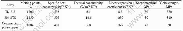
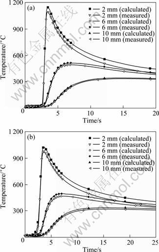
Fig. 3 Thermal cycles of locations on 304 STS plate in different distances from weld centers in two joints: (a) Ti/Fe joint; (b) Ti/Cu/Fe joint
The calculated lateral and longitudinal distribution profiles of the temperature in the Ti/Fe and Ti/Cu/Fe joints are shown in Fig. 4 as the welding time is 6 s. The temperature appears asymmetric in lateral distribution profiles. At the locations in the same distance to the weld center, the values of the titanium alloy plate were higher than those of the 304 STS plate. From the distribution profile, the grade of temperature in the STS plate is greater than that in the titanium alloy plate. This is because that the heat dissipation efficiency of the STS side is higher than that of the titanium side for the larger heat conductivity of STS. For the longitudinal distribution profile, temperatures behind the weld pool are much higher than those ahead for the heat accumulation of the weld. By comparison, it is clear that the temperature of Ti/Cu/Fe joint is lower than that of the Ti/Fe joint at the same location. The heat conductivity of copper is expressly higher than STS or titanium alloy, so the copper filler metal can be considered a ��cold source��. As a result, the grades of temperature in both the two sides are lowered.
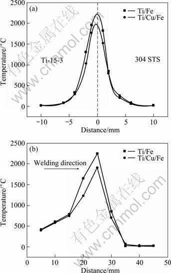
Fig. 4 Calculated temperature distribution profiles of Ti/Fe and Ti/Cu/Fe joints: (a) Lateral distribution: (b) Lengthways distribution
3.2 Thermal stress and residual stress distribution
Figure 5 shows the longitudinal and lateral stress distribution profiles along the direction perpendicular to the weld of the Ti/Fe joint at different time. It can be seen that the longitudinal stress in the weld transformed from compressive stress to tensile stress during the welding process and it increased during the cooling stage. The maximum residual tensile stress is about 260 MPa. Meanwhile, the tensile stress at the STS side is higher than that at the titanium alloy side. While longitudinal stress in HAZ is a relatively low compressive stress. For the lateral stress, it is tensile stress at the STS side with the maximum residual tensile stress of about 88 MPa. At the titanium alloy side, compressive stress only exists in a narrow band. There is tensile stress in the most regions of the plate. This distribution state is mostly dependent on the difference in linear expansion coefficient and yield stress between the two base metals. Similarly, the value at the STS side is higher than that at the titanium alloy side.
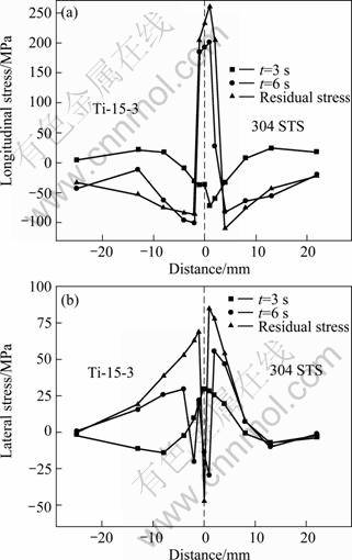
Fig. 5 Stress distribution profiles along direction perpendicular to weld of Ti/Fe joint at different time: (a) Longitudinal stress; (b) Lateral stress
From the above description, the maximum longitudinal and lateral residual tensile stresses emerged in the weld at the STS side and could reach 260 MPa and 88 MPa, respectively. So the brittle electron beam welded Ti/Fe joint fractured in the weld zone near 304 STS [11].
Residual stress distribution profile in the Ti/Cu/Fe joint was calculated and measured as shown in Fig. 6. It is clear that the calculated values of both the lateral stress and longitudinal stress agree with the measured values, which indicates that the calculated results are credible. Similar to the Ti/Fe joint, the maximum lateral and longitudinal residual tensile stresses exist in STS plate near the weld for the same reason. The maximum values are 57 MPa and 194 MPa, respectively. Compared with the Ti/Fe joint, they decrease by 31 MPa and 66 MPa for the low yield strength of commercial pure-copper, which is easy to deform to release the thermal stress. The reduction of the residual stress is helpful to getting the crack free electron beam welded Ti/Cu/Fe joint.
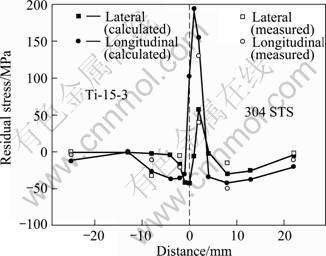
Fig. 6 Residual stress distribution profile in electron beam welded Ti/Cu/Fe joint
4 Conclusions
1) The rotated parabola body heat source model used is fit for the simulation of the temperature field during the electron beam welding of Ti/Fe and Ti/Cu/Fe joints. The calculated values are very close to the ones measured by the thermal couples.
2) The heating rate of the material in the weld region is very high during electron beam welding process. The value is about 1000 ��C/s in the region of 2 mm from the weld center for the Ti/Fe joint. The temperature appears asymmetric in lateral distribution profiles for both the Ti/Fe and Ti/Cu/Fe joints and the values of the titanium alloy plate are higher than those of the 304 STS plate. The copper sheet decreases the peak temperature in the Ti/Fe joint as well as the grades of the temperature.
3) The longitudinal thermal stress transforms from compressive stress to tensile stress during the welding process and the tensile stress increases during the cooling stage. The values at the 304 STS side are higher than those at the titanium side. For the lateral stress, the tensile stress exists in the weld at the STS side.
4) The maximum longitudinal and lateral residual tensile stresses respectively decrease from 260 MPa to 194 MPa, 88 MPa to 57 MPa after the addition of the copper sheet, which proves that copper filler metal is a good candidate for the electron beam welding of titanium alloy to stainless steel from the angle of the residual stress.
References[1] BOYER R R. An overview on the use of titanium in the aerospace industry [J]. Materials Science and Engineering A, 1996, 213(1-2): 103-114.
[2] YUAN X J, SHENG G M, QIN B. Impulse pressuring diffusion bonding of titanium alloy to stainless steel [J]. Materials Characterization, 2008, 59(7): 930-936.
[3] WANG Ting, ZHANG Bing-gang, CHEN Guo-qing, FENG Ji-cai. Problems and research status of welding between dissimilar titanium alloy and steel [J]. Welding & Joining, 2009(9): 29-33. (in Chinese)
[4] ELREFAEY A, TILLMANN W. Solid state diffusion bonding of titanium to steel using a copper base alloy as interlayer [J]. Journal of Materials Processing Technology, 2008, 209(5): 2746-2752.
[5] LI Biao-feng. Study on the weldability of titanium and steel and titanium clad steel plate (I) [J]. Development and Application of Materials, 2004, 19(1): 41-44. (in Chinese)
[6] KUNDU S, CHATTERJEE S. Interface microstructure and strength properties of diffusion bonded joints of titanium-Al interlayer-18Cr-8Ni stainless steel [J]. Materials Science and Engineering A, 2010, 527(10-11): 2714-2719.
[7] KUNDU S, GHOSH M. Diffusion bonding of commercially pure titanium to 304 stainless steel using copper interlayer [J]. Materials Science and Engineering, 2005, 407(1-2): 154-160.
[8] NISHI H. Notch toughness evaluation of diffusion-bonded joint of alumina dispersion- strengthened copper to stainless steel [J]. Fusion Engineering and Design, 2006, 81(1-7): 269-274.
[9] HE P, YUE X, ZHANG J H. Hot pressing diffusion bonding of a titanium alloy to a stainless steel with an aluminum alloy interlayer [J]. Materials Science and Engineering A, 2008, 486(1-2): 171-176.
[10] SUN Z, KARPPI R. The application of electron beam welding for the joining of dissimilar metals: An overview [J]. Journal of Materials Processing Technology, 1996, 59(3): 257-267.
[11] KIM J, KAWAMURA Y. Electron beam welding of Zr-based BMG/Ni joints: Effect of beam irradiation position on mechanical and microstructural properties [J]. Journal of Materials Processing Technology, 2008(207)(1-3): 112-117.
[12] MAGNABOSCO I, FERRO P, BONOLLO F. An investigation of fusion zone microstructures in electron beam welding of copper-stainless steel [J]. Materials Science and Engineering A, 2006, 424: 163-173.
[13] ZHANG H T, HE P, FENG J C, WU H Q. Interfacial microstructure and strength of dissimilar joint Ti3Al/TC4 welded by the electron beam process [J]. Materials Science and Engineering A, 2006, 425(1-2): 255-259.
[14] WANG Ting, ZHANG Bing-gang, CHEN Guo-qing, FENG Ji-cai. Electron beam welding of TA15 titanium alloy to 304 stainless steel [J]. Transactions of the China Welding Institution, 2010, 31(5): 53-57. (in Chinese)
[15] WANG Ting, ZHANG Bing-gang, CHEN Guo-qing, FENG Ji-cai, TANG Qi. Electron beam welding of Ti-15-3 titanium alloy to 304 stainless steel with copper interlayer sheet [J]. Transaction of Nonferrous Metal Society of China, 2010, 20(10): 1829-1834.
[16] ALEMAN B, GUTIERREZ I, URCOLA J J. Interface microstructure in diffusion bonding of titanium alloys to stainless and low alloy steels [J]. Materials Science and Technology, 1993, 9(8): 633-641.
����ͭ�����Ti-15-3�ѺϽ���304����ֵ��������ӹ����е��¶���Ӧ����
�ű���, �� ͢, �����, �¹���, �뼪��
��������ҵ��ѧ �Ƚ����������ӹ����ص�ʵ���ң������� 150001
ժ Ҫ������ͭ��������Ti-15-3�ѺϽ���304����ֽ��е��������ӣ���Ti/Fe��Ti/Cu/Fe��ͷ�ں��ӹ����е��¶ȳ���Ӧ����������ֵģ�����������������������˹��ת����Դ�����ڵ��������ӹ��̵�ģ�⡣�¶ȳ����ں������ijʷǶԳƷֲ����Ѳ���¶ȸ��ڲ���ֲ�ġ���Ӧ��ͬ���ʷǶԳƷֲ���������Ӧ����Ҫ�����ڲ���ֲࡣͭ�������ļ��룬�����˺��ӹ����еķ�ֵ�¶ȡ��¶��ݶ��Լ�����Ӧ��������ͺ��������Ӧ���ֱ���66 MPa��31 MPa�����¶ȳ���Ӧ�����ĽǶȿ��Կ�����ͭ�Ͻ���һ�ֽϺõ�Ti-15-3�ѺϽ���304����ֵ��������ӵ����������ϡ�
�ؼ��ʣ�Ti-15-3�Ͻ�304����֣����������ӣ��¶ȳ���Ӧ����
(Edited by LI Xiang-qun)
Foundation item: Project (2010CB731704) supported by the National Basic Research Program of China; Project (51075189) supported by the National Natural Science Foundation of China
Corresponding author: CHEN Guo-qing; Tel: +86-451-86412911; E-mail: chengguoqing@hit.edu.cn
DOI: 10.1016/S1003-6326(11)61190-4
Abstract: Electron beam welding of Ti-15-3 alloy to 304 stainless steel (STS) using a copper filler metal was carried out. The temperature fields and stress distributions in the Ti/Fe and Ti/Cu/Fe joint during the welding process were numerically simulated and experimentally measured. The results show that the rotated parabola body heat source is fit for the simulation of the electron beam welding. The temperature distribution is asymmetric along the weld center and the temperature in the titanium alloy plate is higher than that in the 304 STS plate. The thermal stress also appears to be in asymmetric distribution. The residual tensile stress mainly exists in the weld at the 304 STS side. The copper filler metal decreases the peak temperature and temperature grade in the joint as well as the residual stress. The longitudinal and lateral residual tensile strengths reduce by 66 MPa and 31 MPa, respectively. From the temperature and residual stress, it is concluded that copper is a good filler metal candidate for the electron beam welding of Ti-15-3 titanium alloy to 304 stainless steel.
