
J. Cent. South Univ. Technol. (2010) 17: 1389-1394
DOI: 10.1007/s11771-010-0647-5![]()
Numerical simulation of aluminum holding furnace with fluid-solid coupled heat transfer
ZHOU Nai-jun(���˾�)1, ZHOU Shan-hong(���ƺ�)1, ZHANG Jia-qi(�ż���)1, PAN Qing-lin(������)2
1. School of Energy Science and Engineering, Central South University, Changsha 410083, China;
2. School of Materials Science and Engineering, Central South University, Changsha 410083, China
? Central South University Press and Springer-Verlag Berlin Heidelberg 2010
Abstract:
To predict three-dimensional temperature distribution of molten aluminum and its influencing factors inside an industrial aluminum holding furnace, a fluid-solid coupled method was presented. The fluid-solid coupled mathematics models of aluminum holding furnace in the premixed combustion processing were established based on mass conservation, moment conservation, momentum conservation, energy conservation and chemistry species conservation. Computational results agree well with the test data of the typical condition. The maximum combustion temperature is 1 850 K. The average temperature of the molten aluminum is 1 158 K, and the maximum temperature difference is about 240 K. The average temperature increases 0.3 �� while the temperature of combustion air increases 1 ��. The optimal excess air ratio is 1.25-1.30.
Key words:
aluminum holding furnace; combustion; heat transfer; fluid-solid coupled; numerical simulation��
1 Introduction
Uniform temperature distribution is of great importance to the heat transfer process (such as the heat transfer between gas and molten aluminum) in aluminum holding furnace [1]. Non-uniform temperature distribution makes the ingot become structure rarefaction and grain size large and also increases wastes. Thus, stable combustion and intensive heat transfer (convection and radiation) were used in the furnace increasingly to boost the output of aluminum holding furnaces and allows improvement of productivity with very low capital investment, which consequently reduces energy consumption. In addition, experimental tests demonstrated that the furnace performance could be improved significantly by optimization of operation parameters [2]. ZIMONT et al [3] developed a computer model to simulate the turbulent combustion of premixed gases in an aluminum holding furnace. Their results were in agreement with experimental data, indicating that the model could be useful for dealing with the simulations of complex geometries. The k-�� model of turbulence and P1 radiation models were adopted in simulating the temperature distribution of the furnace [4-7]. NIECKELE et al [8] examined an aluminum holding furnace in staged combustion by using the model validated by GOMES et al [9], and the flow field and temperature field inside aluminum holding furnace were simulated [10-13].
The fluid-solid coupled heat transfer method was reported in several papers. For example, ZHANG et al [14] researched the temperature field fluid-solid coupled in a flame tube by adopting effective heat transfer efficiency, the k-�� model, and DO (discrete ordinates) radiation and eddy-dissipation model. The results show that the simulation of the temperature field and heat transfer is more reasonable as the interaction between fluid and solid is taken more sufficiently into account. LUO et al [15] obtained the temperature field of the cylinder head and the interface by coupling the interface of solid and fluid to simulate the heat transfer. LIU and SUN [16] calculated complex combustion and heat transfer in hybrid rocket motor (temperature field and gas component distribution) by using fluid-solid coupled heat transfer method.
However, up to now, the aluminum holding furnaces were simulated without considering the molten aluminum in the furnace and neglecting the interaction between combustion space and molten aluminum layer, as a result, the important information on temperature distribution in molten aluminum cannot be obtained. Thus, in this work, the flow field and the temperature distribution of molten aluminum inside an aluminum holding furnace in an aluminum smelter were calculated using the fluid-solid coupled heat transfer method, and the testing data was obtained to examine the simulation results, and influencing factors for the temperature distribution inside the furnace were calculated and analyzed.
2 Mathematical modeling
2.1 Geometric model
Fig.1 illustrates geometry of the furnace, which is simplified as a rectangular frame and includes two parts: a combustion zone and a molten aluminum zone. Both of the burners are set in the same inclination towards the plane of the aluminum bath (��=10?).
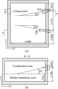
Fig.1 Geometry model of furnace (Unit: mm): (a) Top view; (b) Side view
2.2 Conservation equations
Conservation equations of mass, momentum, energy and species are given as follows:
![]() (1)
(1)
![]() (2)
(2)
![]() (3)
(3)
![]() (4)
(4)
here, turbulent viscosity ��t is defined in accordance with the k-�� model as ��t=c���Ѧ�2/��, where c�� is an empirical constant. Conservation equations of turbulent kinetic energy �� and its dissipation rate �� are as follows.
![]() (5)
(5)
![]() (6)
(6)
The turbulent Prandtl and Schmidt numbers, Prt and Sct, and the Prandtl number for the turbulence kinetic energy Pr�� and its dissipation rate Pr��, are property constants of fluid, and so are c1 and c2 in the equation for the dissipation of the turbulence kinetic energy. Their values were given in Ref.[17].
The temperature field within the furnace was obtained by solving the energy equation for the total enthalpy h, which is defined by the sum of the enthalpies for each species hl, weighted by its mass fraction ml
![]() ,
, ![]() (7)
(7)
where ![]() is the reference temperature (environment temperature); T is the last temperature that the system reaches;
is the reference temperature (environment temperature); T is the last temperature that the system reaches; ![]() is the average heat capacity of species l between
is the average heat capacity of species l between ![]() and T.
and T.
The ![]() term in Eq.(3) represents the enthalpy source due to chemical reactions (combustion) Sreac and the radiation heat transfer Srad. Sreac is given by
term in Eq.(3) represents the enthalpy source due to chemical reactions (combustion) Sreac and the radiation heat transfer Srad. Sreac is given by
![]() (8)
(8)
where hlo is the formation enthalpy of species l, respectively. Rl is the volumetric rate of creation of species l. Therefore, a combustion reaction model is needed.
To calculate the enthalpy source in the fluid due to radiation Srad, P1 transfer radiation model [11] is employed.
The reaction rates in the combustion reactions were calculated by using both Arrhenius and Magnussen models. The reaction rate given by Arrhenius law is
![]() (9)
(9)
where ��l,�� is the stoichiometric coefficient of the molar species l in the ��th reaction; Ml is the molecular weight of species l; T is the temperature; ���� is the temperature exponent; A�� is the pre-exponential factor; E�� is the activation energy; Cj is the molar concentration of each reactant species l; and ��l,�� is the concentration exponent for the reactant species l.
To consider the turbulent effect in the reaction rate, the Magnussen model is employed. The reaction rate is determined as the smallest value in the following two expressions:
![]() (10)
(10)
 (11)
(11)
where mP is the mass fraction of each species of the product; mR is the mass fraction of a particular reactant; R is the reactant which gives the smallest value of Rl,��; A and B are empirical constants which equal 4 and 0.5, respectively.
The key to the coupled calculation of fluid and solid is to realize the heat transfer occurred as the interface of fluid and solid, where the energy from fluid equals the energy absorbed by solid. The conservation can be expressed as:
![]() (12)
(12)
where Kcond is the conduction coefficient of the solid; hconv is the coefficient of heat convection; Tf is the fluid temperature; Tw is the temperature of the wall; and n is sent to the vector.
2.3 Boundary conditions
The computational boundary conditions are shown in Table 1.
On the solid surfaces, a non-slip condition is enforced. However, in the region close to the wall, the universal logarithmic wall functions are employed, following the procedure described by Patankar and Launder. All walls are considered as non-adiabatic, and the heat transfer coefficient (convection and radiation) is obtained by test and their emissivity P=0.8. The boundary conditions of the bottom surface are defined by UDF compiled based on industrial test.
The interface of combustion space and molten aluminum was computed by the way of coupling.
3 Results and discussion
The flow field and temperature field were simulated using a CFD software package (Fluent 6.3). The cases discussed here are the results in stable process.
The flow field and temperature field of the section Z=1.8 m are shown in Fig.2. As shown in Fig.2(a), the maximum velocity is found at the outlet of 1# burner, and the gas flows jetting from 1# burner form a large vortex, which is related to the structure of furnace and the size of the burners. The temperature distribution in the same section is shown in Fig.2(b), in which the maximum combustion temperature is about 1 850 K. It is also obvious that the flame caused by 1# burner is longer and narrower compared with that caused by 2#, because of the vortex and the smaller size of 1# burner. The shape and size of the flames are according with those observed in industrial locale. It can be found that the temperature is evidently lower near door jamb because the thermal conductivity of door is larger than that of the other walls.
Fig.3 shows the temperature distribution in the molten aluminum layer. Fig.3(a) shows that the maximum temperature is about 1 260 K, the minimum temperature is about 1 020 K, and the average temperature of the plane is about 1 180 K. The high temperature region is near combustors, because the region is affected strongly by the flames radiation. It is obvious that the stratification phenomenon of the temperature distribution in the section of X=5 m appears, which is due to the radiation and convection heat transfer, as shown in Fig.3(b).
Table 1 Boundary conditions of calculation
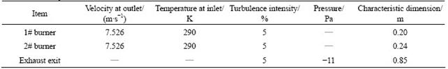
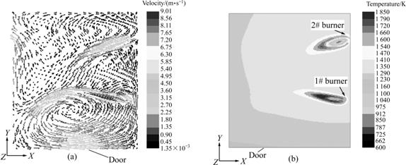
Fig.2 Distribution of velocity (a) and temperature (b) in plane Z=1.8 m
Fig.3 Temperature field in molten aluminum: (a) Temperature field in plane of Z=0.6 m; (b) Temperature field in section of X=5 m
The temperature in the combustion space was measured at several representative points, which were located in the same line along X-axis, 1 m above furnace bottom and 3 m from the door. The trend of the curve is related to the flames distribution inside the furnace. The comparison between computed and measured results is shown in Fig.4.
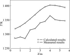
Fig.4 Comparison of temperature between computational data and test data in combustion space
The calculated results are in good agreement with the test data. However, the calculated results are larger than the measured results, which is mainly due to the opening of the door during the test. As cold air is absorbed into the combustion space under the negative pressure, the whole temperature in the furnace decreases.
In a word, the computational models were proved to be reliable and accurate by comparing the calculated results with the test data, from which the relative error is less than 5%.
4 Influencing factors analysis
4.1 Temperature of combustion air
The maximum combustion temperature increases gradually with the mixture temperature increasing, as shown in Fig.5(a), because preheating combustion air can raise its activation energy and release more energy in unit combustion space. In addition, high temperature air brings energy to the combustion space, which results in higher combustion temperature. However, it must be noted that higher combustion temperature may cause higher NOx emission to the environment. Thus, avoiding an excessively high temperature of combustion air is necessary.
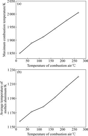
Fig.5 Influence of temperature of combustion air on: (a) Maximum combustion temperature; (b) Average temperature of molten aluminum
Fig.5(b) shows that average temperature in the metal increases along with the increase of fuel-air mixture temperature, which demonstrates that higher combustion air temperature causes more intensive heat transfer from combustion space to metal. This shows that when the temperature of combustion air increases by 50 ��, the average temperature of the molten aluminum increases by 15 ��. Thus, the influence of the temperature of combustion air on the average temperature of the molten aluminum is great and the increasing rate of temperature is relatively fast. The average temperature of combustion apace inside furnace is greatly influenced by the combustion air temperature, and high average temperature of combustion space can enhance the heat transfer between combustion space and molten metal layer.
4.2 Excess air ratio
Fig.6 shows that the influence of the excess air ratio on two parameters described preciously is dramatic. From Fig.6(a), it can be seen that the maximum combustion temperature decreases gradually with the increase of the excess air ratio. This is due to the fact that increasing the excess air ratio will dilute the concentration of fuel-air mixture. As a result, the activation energy decreases, the maximum combustion temperature decreases and NOx emissions reduce consequently, which could be a feasible method to counteract the high comcombustion temperature caused by high combustion air temperature.
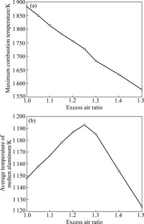
Fig.6 Influence of excess air ratio on: (a) Maximum combustion temperature; (b) Average temperature of molten aluminum
In addition, the increase of air flux enhances the gas flow velocity and turbulent intensity in the furnace. Therefore, heat flux caused by convection increases, that is, more heat is transferred into the metal layer. So, its temperature increases. However, if the excess air ratio is large enough, the increase of the average temperature of molten aluminum will decrease subsequently, and it can reach the maximum value when the excess air ratio is between 1.2-1.3, as shown in Fig.6(b).
5 Conclusions
(1) The computational models are proved to be reliable and accurate by comparing the calculated results with the test data, and the relative error is less than 5%.
(2) The simulation results show that the maximum temperature difference in molten aluminum is about 240 K, which illuminates that the temperature is not uniform, and some measures are necessary, for example, adopting the gas stirring technology.
(3) By calculating the influence of excess air ratio on the average temperature of molten aluminum, the optimal excess air ratio is 1.25-1.30 for the aluminum holding furnace in the aluminum smelter.
(4) Adopting high temperature of combustion air and relative large excess air ratio is an appropriate combustion mode, which can reduce energy consumption and reduce emissions of NOx.
References
[1] YU Yan-dong, JIANG Hai-yan, LEI Li, ZENG Xiao-qin, ZHAI Chun-quan, DING Wen-jiang. Numerical simulation of die casting process of magnesium alloy [J]. Journal of Central South University: Science and Technology, 2006, 37(5): 867-873. (in Chinese)
[2] NIECKELE A O, NACCACHE M F, GOMES M S P. Numerical modeling of an industrial aluminum melting furnace [J]. Journal of Energy Resources Technology, 2004, 126: 72-80.
[3] ZIMONT V, POLIFKE W, BETTELINI M. An efficient computational model for premixed turbulent combustion at high Reynolds numbers based on a turbulent flame speed closure [J]. Journal of Engineering for Gas Turbins and Powder, 1998, 120(3): 526-532.
[4] WU Wu-hui, LI Shui-ping. Research on numerical simulation of the temperature field in the ceramics rolling kiln [J]. Industry Heat, 2007, 36(3): 35-38. (in Chinese)
[5] TONG Jian-hui, FENG Qing, WANG He-ping. Numerical simulation of the gas flows and temperature field in the firing zone of roller hearth kiln [J]. China Ceramics, 2006(5): 27-30. (in Chinese)
[6] SHEN Jin-lin, HU Ling-yun. Three-dimensional mathematic modeling of turbulent combustion in combustion space of oil-fired float glass melting furnace [C]// The International Conference on Glass XV��. Shanghai, 1997: 65-71. (in Chinese)
[7] SHEN Jin-lin, ZHU Jian-feng, YAN Hui. Study on mechanism of glass and heat-transfer process in float glass furnace using computer three-dimensional simulation and graphic generation [J]. Glass Technology Glass Archemetry, 1995, 6: 133-139.
[8] NIECKELE A O, NACCACHE M F, GOMES M S P, KOBAYSHI W T. Numerical simulation of a three dimensional aluminum melting furnace [C]// Proc 4th Int Conf on Technology and Combustion for a Clean Environment. Lisbon, 1997, II 36(3): 15-20.
[9] GOMES M S P, NIECKELE A O, NACCACHE M F, KOBAYSHI W T. Numerical investigation of the oxygen enriched combustion process in a cylindrical furnace [C]// Proc 4th Int Conf on Technology and Combustion for a Clean Environment. Lisbon, 1997, II 36(1): 1-5.
[10] NIECKELE A O, NACCACHE M F, GOMES M S P, KOBAYSHI W T. Numerical investigation of the staged versus non-staged combustion process in an aluminum melting furnace [J]. Heat Transfer Division, 1998, 357(1): 253-259.
[11] NIECKELE A O, NACCACHE M F, GOMES M S P, KOBAYSHI W T. The influence of oxygen injection configuration on the performance of an aluminum melting furnace [J]. Heat Transfer Division, 1999, 364(2): 1303-1317.
[12] BREWSTER B S, WEBB B W, MCQUAY M Q, D��AGOSTINI M, BAUKAL C E Jr. Combustion measurements and modelling in an oxygen enriched aluminum-recycling furnace [J]. Journal of the Institute of Energy, 2001, 74: 11-17.
[13] MUKHOPADHYAY A, PURI I K, ZELEPOUGA S, RUE D M. Numerical simulation of methane-air nozzle burners for aluminum remelt furnaces [J]. Heat Transfer Division, 2001, 369(4): 65-71.
[14] ZHANG Li-fen, WU Ding-yi, LIU Zhen-xia. Numerical calculation of the three-dimensional wall temperature of the combustion chamber by using heat-flow coupled method [J]. Turbine Technology, 2006(4): 275-277. (in Chinese)
[15] LUO Qing-guo, LIU Hong-bin, GONG Zheng-bo. Study on the fluid-solid coupled heat transfer of the diesel engine cylinder head [J]. Acta Armamentarii, 2008, 29(7): 669-773.
[16] LIU Shang, SUN De-chuan. Flow-structure coupled heat transfer calculation for a diffusion flame experimental burner [J]. Journal of Propulsion Technology, 2008, 29(6): 257-261.
[17] FAN Qun-bo, WANG Lu, WANG Fu-chi. Numerical simulation of temperature and velocity fields in plasma spray [J]. Journal of Central South University of Technology, 2007, 14(4): 496-499.
Foundation item: Project(2006AA03Z523) supported by the National High-Tech Research and Development Program of China; Project(08C26224302178) supported by the Innovation Foundation of Central South University, China
Received date: 2009-12-29; Accepted date: 2010-03-01
Corresponding author: ZHOU Nai-jun, PhD, Professor; Tel: +86-13973160806; E-mail: njzhou@mail.csu.edu.cn
