
J. Cent. South Univ. Technol. (2011) 18: 1105-1114
DOI: 10.1007/s11771-011-0810-7![]()
Design and control of integrated pneumatic dexterous robot finger
WANG Zhi-heng(��־��), ZHANG Li-bin(������), BAO Guan-jun(���پ�),
QIAN Shao-ming(Ǯ����), YANG Qing-hua(���컪)
Key Laboratory of Special Purpose Equipment and Advanced Processing Technology,
Ministry of Education and Zhejiang Province, Zhejiang University of Technology, Hangzhou 310032, China
? Central South University Press and Springer-Verlag Berlin Heidelberg 2011
Abstract:
Based on flexible pneumatic actuator (FPA), bending joint and side-sway joint, a new kind of pneumatic dexterous robot finger was developed. The finger is equipped with one five-component force sensor and four contactless magnetic rotary encoders. Mechanical parts and FPAs are integrated, which reduces the overall size of the finger. Driven by FPA directly, the joint output torque is more accurate and the friction and vibration can be effectively reduced. An improved adaptive genetic algorithm (IAGA) was adopted to solve the inverse kinematics problem of the redundant finger. The statics of the finger was analyzed and the relation between fingertip force and joint torque was built. Finally, the finger force/position control principle was introduced. Tracking experiments of fingertip force/position were carried out. The experimental results show that the fingertip position tracking error is within ��1 mm and the fingertip force tracking error is within ��0.4 N. It is also concluded from the theoretical and experimental results that the finger can be controlled and it has a good application prospect.
Key words:
1 Introduction
As final executing manipulators for robot to interact with environment, the robot hand (always called robot end-effector) plays an important role to improve the dexterity and intelligent level [1]. Earlier conventional industrial robot end-effectors had simple structure and were limited to one degree of freedom (DOF), which restricted the development and application of robots [2]. So, the robot multi-fingered dexterous hand with multiple joints and multiple degrees of freedom has been pursued by many researchers. From 1970s, different kinds of multi-fingered dexterous hands have been developed. The representative multi-fingered hands are as follows [3-6]: Okada hand developed by Japanese Electronic Technology Lab in 1974, the Stanford/JPL hand developed by Stanford University and the Utah/MIT hand proposed by MIT and University of Utah in 1980, the DLR hands developed by German Aerospace Center and the Robonaut hand developed by United States National Aeronautics NASA in 1990, the dexterous hand based on the pneumatic artificial muscles developed by Shadow Robot Company in the early 21st century. The Robot Research Institute of Beijing University of Aeronautics and Astronautics has developed BH dexterous hands. Harbin University of Technology has developed the HIT hand.
Most of the robot multi-fingered hands mentioned above are driven by electric motors, and few of them are driven by pneumatic pistons or pneumatic muscle actuators (PMAs). Multi-fingered hands driven by motors can realize high position control precision. In order to get greater fingertip force with a smaller overall size, multi-fingered hands driven by motors mostly have motors placed on the forearm or the wrist of the robot and finger joints are driven by cable-conduit mechanism [7]. This motor-cable driven scheme results in many disadvantages, such as 1) the hand structure is complex and the size is always large; 2) additional cable tension sensing mechanism is required, and it is difficult to realize real-time control and accurate control; 3) when power is transmitted by cables, additional friction in the servo loop is difficult to avoid, which makes the hand have low efficiency. The structure of multi-fingered hand driven by PMAs (Shadow hand) or pneumatic positions (Utah/MIT hand) is simple, but they also have some disadvantages as follows. 1) Actuators and robot hands are separated, and joints are all cable driven. Friction, relaxation and energy loss are difficult to avoid. 2) There is no unified mathematical model for PMAs, so the fingertip output force and the joint position are difficult to control. 3) Many PMAs or pneumatic positions make the robot forearms much bigger.
In recent years, a robot hand project has also worked on by Zhejiang University of Technology, China. The aim of this project is to develop an integrated multi-sensory pneumatic multi-fingered dexterous hand named ZJUT hand based on flexible pneumatic actuator (FPA) [8-10] which can make up for the deficiency of existing robot hands. As shown in Fig.1, ZJUT hand has five fingers with 20 DOFs in total, and its size is approximately 1.5 times as large as human hand. Each finger has four DOF and four joints. The characteristics of this hand are as follows. 1) The mechanical parts and FPAs of the joint are integrated. Driven by FPA directly, no additional power transfer devices (such as cables, gears and artificial tendons) are needed, thus the friction is small and the vibration can be avoided. 2) Because the joint torque is output directly, the fingertip output force can be controlled easily. 3) FPA has greater specific power. Except for above advantages, ZJUT hand also has characteristics of simple structure, good adaptability, great passive compliance and adequate grasp rigidity.
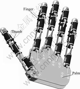
Fig.1 Three-dimensional model of ZJUT hand
Robot multi-fingered dexterous hand usually consists of 3-5 fingers. Each finger can be seen as a small articulated robot which can be independently controlled. So, the kinematics, dynamics and trajectory planning of the finger is the basis of study on the multi-fingered hand. The aim of this work is to introduce the finger of the ZJUT hand, to illustrate the unique mechanism used to actuate each joint and the sensory system, to analyze the kinematics and statics of the finger and to experimentally test a prototype finger.
2 Structure of ZJUT hand��s finger
2.1 Overall description
The structure and the photo of the finger are shown in Fig.2. The finger was designed based on the following concepts: 1) Each finger is designed as a module; 2) The overall appearance and performance of the finger should resemble a human finger as closely as possible. The finger with force/position sensors proposed has four DOFs and four joints: two for the metacarpal phalangeal (MCP) joint, one for the proximal interphalangeal (PIP) joint, and one for the distal interphalangeal (DIP) joint.
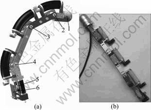
Fig.2 Pneumatic dexterous finger of ZJUT hand: (a) Structure of finger (1��Five-component force/torque sensor; 2, 3, 4��Bending joint I, II, III; 5��Side-sway joint; 6��Contactless angle sensor); (b) Photo of finger
2.2 Drive system of finger
The drive system of the pneumatic finger consists of three bending joints and one side-sway joint. As shown in Fig.3, the bending joint consists of a FPA, a rotating shaft, two connecting rods, four connecting parts and a pipe connector, and FPA is composed of a rubber tube, two covers and a helical steel wire embedded in the wall of the rubber. Each end of rubber tube is sealed by a cover. Covers and connecting parts are fixedly linked, and connecting rods and connecting parts are linked by screws.
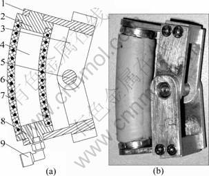
Fig.3 Bending joint based on FPA: (a) Structure of bending joint (1��Connect part; 2, 8��Covers; 3��Connecting rod; 4��FPA; 5��Rotating shaft; 6��Rubber tube of FPA; 7�� Helical steel wire of FPA; 9��Pipe connector); (b) Photo of bending joint
The working principle of the bending joint is as follows. Compressed air fills into the FPA by the pipe connector. Under the high pressure of compressed air inside FPA, the rubber tube will expand. Because the helical steel wire restrains its deformation in the radial direction, FPA will stretch in the axial direction and then promotes the connecting rod trough the connect part. The connecting rod will rotate around the axis through the centre of the shaft. When the FPA is deflated, it will return to its original state, due to the elastoplasticity of rubber tube. Then, the FPA will pull the connecting parts until the joint returns to its original state. The air pressure in the FPA is adjusted properly, and then the bending angle can be controlled.
The relationship between bending angle and the air pressure inside FPA was profoundly analyzed, the static model was built, and the static and dynamic characteristics were experimentally tested [11]. The static models about the angle and force of the bending joint are
 (1)
(1)
![]() (2)
(2)
![]() (3)
(3)
where t0 is the shell thickness of rubber tube of FPA; �� is the bending angle of the joint; l is the original length of rubber tube of FPA; E is the elastic modulus of the rubber; r0 is the mean radius of the rubber tube of FPA; H is the distance between the center of the shaft and the axis of the rubber tube; p is air pressure inside FPA; patm is the atmospheric pressure; ��p is the pressure increment; F and ��out are the output force and torque of the bending joint under ��p, respectively.
The side-sway joint based on FPA has been proposed. The structure and the photo of the side-sway joint are shown in Fig.4. It is basically composed of two FPAs, two T-type connecting rods, two pipe connectors and a rotating shaft. Two FPAs distribute symmetrically. The covers of the FPA and T-type connecting rods are fixedly linked. As shown in Fig.5, one T-type connecting rod has a circular hole on the bottom, and the other one has two waist-shaped holes on the bottom. Through the gain structure, an axial stretching revolute pair is formed with two T-type connecting rods and a rotating shaft.
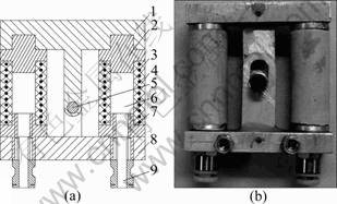
Fig.4 Side-sway joint based on FPA: (a) Structure of side-sway joint (1, 8��T-type connecting rods; 2, 7��Covers of FPA; 3�� Helical steel wire of FPA; 4��FPA��s rubber tube; 5��Rotating shaft; 6��FPA; 9��Pipe connector of FPA); (b) Photo of side- sway joint
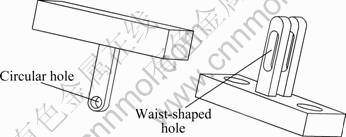
Fig.5 Two kinds of T-type connecting rods
The working process of the side-sway joint is as follows. Before the bending movement, the same pressure compressed air fills into the two FPAs. So, they will have same stretch length. Because of waist-shaped holes of the connecting rod mentioned above, the side-sway joint will stretch along the axial direction, but never bend in other direction. Then, changing the pressure of compressed air in the two FPAs, the two FPAs will have different stretch lengths. If the stretch length of left FPA is greater than that of the right one, the joint will bend to the right side, and vice versa. When deflating the two FPAs, the side-sway joint will return to its original state due to the elastoplasticity of rubber tube. The bending angle of the side-sway joint can be adjusted by controlling the air pressure inside two FPAs.
The relationship between bending rotation angle and air pressure inside two FPAs was also obtained and experiments to test their static and dynamic characteristics were carried out [12]. The static model of the side-sway joint about force is similar to bending joint. The static model of side-sway joint about angle is
 (4)
(4)
 (5)
(5)
where pl and ps are the air pressures inside two FPAs, respectively; a is the distance between the axis of the two FPAs; L is the length of two FPAs that have pre-elongation. The other notations have the same meanings with the static models of bending joint.
Joints design is one of the key issues for developing a robot hand. The spatial dimension and function of a robot hand is directly determined by the structure and dexterity of the joints. The characteristics of the joints mentioned above can be summarized as follows.
1) These two joints are directly driven by FPA and have advantages of good adaptability, simple structure and little energy loss. The length of the lever arm vector is constant, so the output torque can be controlled easily.
2) Because of compressibility of air and flexibility of the rubber, the stiffness of FPA is low, thus the flexibility of the rotary pair of the joints is better. Except FPA, the other parts of the joints are rigid components which can improve the rigidity of the joints. As a human hand is not rigid, but allows for great flexibility in the relaxed condition, and some flexibility in the tight condition, the finger in this work provides adequate compliance. These stiffness/compliance characteristics make this joint simulate the human hand joints well.
2.3 Sensory system of finger
A robot multi-fingered hand should be equipped with a set of good position and force sensors which enable control schemes for a robot hand to grasp and manipulate objects. The sensors should have small size and reduce the impact on the hand as small as possible.
Each joint of the finger in this work is equipped with a contactless magnetic rotary encoder AS5045 manufactured by Austriamicrosystems AG. Combining integrated Hall elements, AS5045 can calculate accurate angular measurement over a full turn of 360�� with a resolution of 0.087 9��. It has the benefits as Ref.[13]: 1) complete system-on-chip, 2) ideal for applications in harsh environments due to contactless position sensing, 3) no calibration required, and 4) small Pb-free package: SSOP 16 (5.3 mm��6.2 mm).
As shown in Fig.6, the angular position sensory system developed in this work consists of an embedded microprocessor based on DSP, a data line and a small PCB board with an AS5045. AS5045 can be fixed on the joint by the small PCB board. To measure the joint angle, only a simple two-pole magnet fixed on the end of the shaft of the joint, rotating over the center of the AS5045 is required, as shown in Fig.7. The angle sensor is contactless with the joint, so it has no influence on the joint.
Except for the angle of joints, when a robot hand grasps or manipulates the objects, the force between objects and fingertips should be obtained. According to the joint angle/fingertip force information, we can determine whether the hand grasp or manipulation is stable. As shown in Fig.8, a miniaturized five-component force/torque sensor with digital output is fixed to the fingertip. The technical parameters of the force sensor with a double metallic slice of E-Film structure are listed in Table 1.
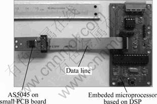
Fig.6 Joint angle position sensory system
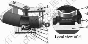
Fig.7 Schematic diagram of joint angle measurement: 1�� Bending joint; 2��FPA; 3��Rotary shaft; 4��Two-pole magnet; 5��AS5045; 6��PCB board
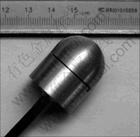
Fig.8 Photo of five-component force/torque sensor
3 Kinematics of ZJUT hand��s finger
3.1 Direct kinematics of finger
The kinematics definition for one finger is shown in Fig.9. The origin of the base frame is built on the rotary shaft of the side-sway joint. The D-H parameters of the finger are listed in Table 2.
Table 1 Technical parameters of force sensor
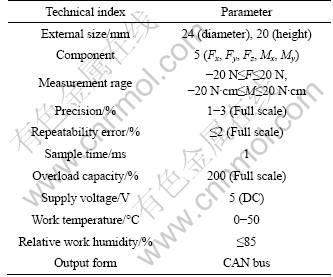
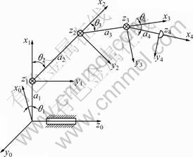
Fig.9 Link model of finger
Table 2 D-H parameters of finger

According to Fig.9, the transformation matrix of the finger can be obtained:
![]()
 (6)
(6)
For convenience, we define : ci=cos��i; si=sin��i; cij= cos(��i+��j); sij=sin(��i+��j); cijk=cos(��i+��j+��k); sijk=sin(��i+��j+ ��k); i, j, k=1, 2, 3, 4.
From Eq.(6), the coordinates of fingertip relative to the base frame are
![]() (7)
(7)
![]() (8)
(8)
![]() (9)
(9)
According to the above analysis, the direct kinematics of the finger is easy and intuitive, and has a unique solution.
3.2 Workspace of finger
Workspace is the volume of space that the fingertip can reach under the actuators and structure limitation of finger. Substituting the data in Table 2 into the direct kinematics equations and using the simulation software MATLAB, the finger 3D workspace and its project view in 2D coordinate plane relative to the base frame can be obtained, as shown in Fig.10. Through analyzing the workspace, the structure parameters of the finger can be further optimized.
3.3 Inverse kinematics of finger
Motion planning and control of a robot finger is often a process of solving the inverse kinematics. The problem of solving the inverse kinematics is a nonlinear one that involves the existence of solutions, the uniqueness of solutions, the optimality of solutions and so on. The problem whether solutions exist or not entirely raises the question of the workspace of finger [14].
Given the coordinate value ![]() of fingertip relative to the base frame, substituting Eq.(7) into Eq.(8), the bending angle ��1 of side-sway joint can be obtained with an unique solution in the range of [-15��, 15��] :
of fingertip relative to the base frame, substituting Eq.(7) into Eq.(8), the bending angle ��1 of side-sway joint can be obtained with an unique solution in the range of [-15��, 15��] :
![]() (10)
(10)
Four joints of the finger in this work are not mechanically coupled each other. Using algebra theory, it can be seen that except ��1 has a unique solution, the other three joint angles have no unique solutions, thus there exits a redundant problem. At present, four methods are always applied to solve the inverse kinematics problem of the redundant robot finger. They are geometric method, algebraic method, numerical iteration method and artificial intelligent method [15]. Geometric method suffers from a lack of generality; algebraic method is only suitable for the robot finger with a few joints; Numerical iteration method can get one solution derived from a variety of iterative solutions, but it is difficult to guarantee the correctness of solutions; artificial intelligent method with its own unique advantages becomes the research trend [16-18].
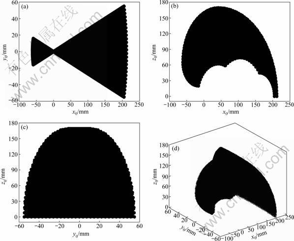
Fig.10 Simulation of finger workspace: (a) Projection view in x0y0-plane; (b) Projection view in x0z0-plane; (c) Projection view in y0z0-plane; (d) 3D workspace in x0y0z0-space
An improved adaptive genetic algorithm (IAGA) is applied to solve the inverse kinematics problem of the finger in this work. IAGA uses binary coding, survival of the fittest selecting mode, adds new individuals dynamically and introduces a self-adaptive genetic operator based on population concentration-dispersion. It can avoid the population premature convergence, improve the speed of convergence and obtain a global solution effectively. To implement the IAGA, there are some key issues as follows.
1) Fitness function
Fitness function is an interface between GA and the optimization problem. Through the fitness function, the fitness value of each individual (solution) will be calculated. According to the fitness value, we can judge whether the individual is good or bad. The smaller the fitness value of the individual, the closer to the calculation the optimal solution, and vice versa. Combining with analysis on the direct kinematics, the fitness function is built:
![]()
![]()
![]() (11)
(11)
where ��=(��1, ��2, ��3, ��4).
2) Constraints
According to the structure and performance of the joints, the corresponding constraints suitable for this finger are built:
 (12)
(12)
3) Self-adaptive genetic operator
To avoid the divergence or getting a local minimum, it is necessary to adjust the crossover probability Pc and mutation probability Pm adaptively when the IAGA is running. A self-adaptive genetic operator based on population concentration-dispersion is adopted in this work. Self-adaptive crossover probability Pc and mutation probability Pm proposed are
![]()
 (13)
(13)
![]()
 (14)
(14)
where fmax is the maximum population fitness value; fmin is the minimum population fitness value; favg is the average population fitness value; ![]() is the larger fitness value of two cross individuals; f is the fitness value of the mutation individual; Pc,max and Pc,min are the maximum and minimum crossover probabilities, respectively; Pm,max and Pm,min are the maximum and minimum mutation probabilities, respectively; a is the population concentration-dispersion factor (0.5
is the larger fitness value of two cross individuals; f is the fitness value of the mutation individual; Pc,max and Pc,min are the maximum and minimum crossover probabilities, respectively; Pm,max and Pm,min are the maximum and minimum mutation probabilities, respectively; a is the population concentration-dispersion factor (0.5
From Eq.(13) and Eq.(14), Fig.11 can be obtained. As shown in Fig.11, no matter what state of the population, Pc and Pm decrease with the increase of the fitness value. The individuals with greater fitness value have smaller Pc and Pm, thus the excellent individuals will be protected and not be destroyed, and vice versa. When the population concentrates, crossover operation cannot change the state of the population. To improve the population diversity and avoid premature, Pm should be increased and Pc should be decreased. When the population disperses, Pc should be increased, Pm should be decreased and the excellent individuals are ensured not to be damaged.
Under MATLAB and Sheffield GA toolbox environment, IAGA is applied to carry out the simulation experiments for analyzing the inverse kinematics of the finger. The simulation parameters are listed in Table 3. Given the coordinate values of the fingertip (120, 20, 75), when the fitness value is less than 10-7, the simulation results can be obtained, as shown in Fig.12. It can be seen that IAGA stops running in the 147th generation. Then, the best fitness value of 4.551 1�� 10-8 and a set of optimal solutions will be obtained. It is concluded from the simulated results that the IAGA proposed in this work can effectively solve the inverse kinematics problem of the redundant finger.
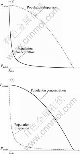
Fig.11 Distributions of Pc and Pm: (a) Crossover probability Pc; (b) Mutation probability Pm
Table 3 Simulation parameters of IAGA
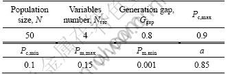
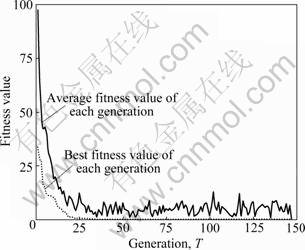
Fig.12 Simulation curves of inverse kinematics of finger
4 Statics of ZJUT hand��s finger
4.1 Mapping fingertip force to equivalent joint torques
According to the robotics, there is
![]() (15)
(15)
where ��=[��1 ��1 ��1 ��1]T, is a 4��1 vector of joint torques. 0F=[0fx 0fy 0fz 0mx 0my 0mz], is a 6��1 force- moment vector acting at the fingertip, and 0F is the general force with respect to the base frame. JT is the Jacobian transpose with respect to base frame.
In this work, the Jacobian J of the finger with respect to the base frame is
![]()
 (16)
(16)
For convenience, P=a4c234+a3c23+a2c2+a1, Q= a4s234+a3s23+a2s2, and R=a4s234+a3s23 are defined.
4.2 Transformations of fingertip force
The fingertip output force 4F=[4fx 4fy 4fz 4mx 4my 4mz] relative to the fingertip frame (tool frame) is a 6��1 force-moment vector, as shown in Fig.9. Because the joints of the finger can only realize bending movement and not torsion movement, the sub-moment 4mx at x4-axis of 4F is very small and can be neglected. Thus, a five-component force/torque sensor is chosen. 0F in Eq.(15) is relative to the base frame, and 4F is also the fingertip force sensor output force with respect to the fingertip frame. So, the fingertip force 4F is mapped from the fingertip frame to the base frame. From robotics and Eq.(6), the mapping relationship between 4F and 0F can be obtained:
![]()
 (17)
(17)
5 Experimental system and results
5.1 Finger force/position control principle
There are always two kinds of schemes for controlling robot fingers: joint space control schemes and cartesian space schemes. Joint space control schemes have characteristics of simple algorithm, low real-time computation and high control precision. That is why most robot multi-fingered dexterous hands adopt the joint space control schemes at present.
A block diagram of the finger force/position closed loop control system proposed in this work is shown in Fig.13. The control principle is: Given the goal position and orientation PT of the fingertip in cartesian coordinates, using the inverse kinematics, a set of joint angles ��T that correspond to the goal position and orientation can be calculated. The joint controllers can make use of the joints feedback from angle sensors to keep the actual joint angles �� following the desired angle ��T. Then, the fingertip actual position and orientation PA will be calculated by using the direct kinematics for tracking the desired fingertip trajectory. When the joint angles are certain, Eq.(15) can be used to compute the joint torques ��T that correspond to the given goal fingertip output force FT. Using the feedback form the force sensor, this control system will output the actual fingertip force FA tracking the desired fingertip force.
5.2 Experiments of finger
Based on the above analysis, the finger experimental platform is built, as shown in Fig.14. Industrial personal computer (IPC) sends five-channel analog voltage signals by D/A converters which can adjust output air pressure of five electro-pneumatic regulators (SMC: ITV0050-3BS) connected with FPAs of the joint. Under the air pressure, the joints will have a bending angles which are measured by the AS5045 and sent to IPC by CAN bus. At the same time, the pressure inside FPAs feeds back to the IPC via the pressure sensor in the electro-pneumatic regulator. Then, the fingertip force is measured by five-component force/torque sensor and also sent to the IPC by CAN bus. Combining Delphi and the MATLAB, the PC control and graphics display software are developed.
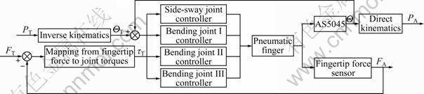
Fig.13 Block diagram of finger force/position control system
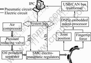
Fig.14 Schematic diagram of experimental system
Static force/position tracking experiments of the finger are carried out. When the fingertip output force F=0, and a desired fingertip position trajectory: z0=30? sin[(��/40)x0]+100 is given, the tracking curve in x0z0- plane (base frame) is shown in Fig.15.
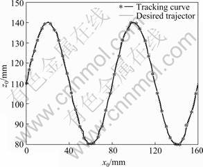
Fig.15 Fingertip position tracking curves
It can be observed from Fig.15 that the static fingertip position tracking result is good and the tracking error is within ��1 mm. Because of the output force F=0, fingertip position tracking accuracy depends mainly on the joints control precision.
When the fingertip is fixed, a desired fingertip output force trajectory is a triangular waveform which is described as
 (18)
(18)
The tracking results are obtained, as shown in Fig.16. It can be found from Fig.16 that there is an error between the tracking curve and the desired curve, and the error is within ��0.4 N. The causes of this error are: 1) The air cavity of the rubber tube of FPA is small, thus the air pressure inside FPA is more sensitive to the electro- pneumatic regulators, which can result in the oscillation of fingertip output force; 2) The irregular deformation of FPA is formed under the air pressure; 3) The fingertip force sensor leads to noise.

Fig.16 Fingertip output force tracking curves
6 Conclusions
1) Based on a new type of pneumatic actuator PFA, a stiffness/compliance 4-DOF robot finger integrated with position/force sensors was proposed. It can simulate the human finger well. Each joint can move independently. Driven by FPA directly, the unique mechanism makes the finger have some characteristics, such as small friction, no vibration, simple structure, good adaptability, great passive compliance, small overall size and adequate grasp rigidity.
2) An improved adaptive genetic algorithm IAGA was proposed. It can effectively solve the inverse kinematics problem of the redundant finger.
3) Static force/position tracking experiments of the finger were carried out. The results show that the finger position tracking error is within ��1 mm and the fingertip output force tracking error is within ��0.4 N. With reference to the experimental results, it is concluded that the pneumatic robot finger can be well controlled by the closed loop control system based on the angle and force sensors.
References
[1] JIANG Li, CAI He-gao, LIU Hong. New type integrated humanoid finger and its dynamics analysis [J]. Chinese Journal of Mechanical Engineering, 2004, 40(4): 143-149. (in Chinese)
[2] LIU Jie, ZHANG Yu-ru. Design and implement a system of grasp identification for dexterous robot hand [J]. Robot, 2003, 25(3): 259-263. (in Chinese)
[3] OKADA T. Computer control of multijointed finger system for precise handling [C]// Proceeding of the IEEE Conference on Systems, Man, and Cybernetics. San Diego: IEEE Press, 1982: 289-299.
[4] JACOBSEN S, WOOD J, KNUTTI D, BIGGERS K B. Utah/MIT dexterous hand: Work in progress [J]. The International Journal of Robotics Research, 1984, 3(4): 21-50.
[5] HIRZINGER G, FISCHER M, BRUNNER B, KOEPPE R, OTTER M, GREBENSTEIN M, SCH?FER I. Advances in robotics: The DLR experience [J]. The International Journal of Robotics Research, 1999, 18(11): 1064-1087.
[6] LIU H, MEUSEL P, SEITZ N, WILLBERG B, HIRZINGER G. The modular multisensory DLR-HIT-Hand [J]. Mechanism and Machine Theory, 2007, 42(5): 612-625.
[7] YANG J Z, PITARCH E P, KARIM A M, PATRICK A, LINDKVIST L. A multi-fingered hand prosthesis [J]. Mechanism and Machine Theory, 2004, 39(6): 555-581.
[8] ZHANG Li-bin, BAO Guan-jun, YANG Qing-hua, RUAN Jian, QI Li-yong. Static model of flexible pneumatic bending joint [C]// Proceeding of the 2006 9th Int Conf Control, Automation, Robotics and Vision. Singapore, 2006: 1749-1753.
[9] ZHANG Li-bin, WANG Zhi-heng, YANG Qing-hua, SHAO Tie-feng, BAO Guan-jun. Kinematics model and simulation of 5-DOF finger based on flexible pneumatic actuator [J]. Computer and Computing Technologies in Agriculture, 2008, 2(259): 777-790.
[10] WANG Zhi-heng, BAO Guan-jun, ZHANG Li-bin, YANG Qing-hua. Development and control of flexible pneumatic wall-climbing robot [J]. Journal of Central South University of Technology, 2009, 16(6): 961-970.
[11] QIAN Shao-ming, YANG Qing-hua, BAO Guan-jun, WANG Zhi-heng, ZHANG Li-bin. Research on basic characteristics of bending joint based on flexible pneumatic actuator FPA [J]. China Mechanical Engineering, 2009, 20(24): 2903-2907. (in Chinese)
[12] ZHANG Li-bin, WANG Zhi-heng, BAO Guan-jun, QIAN Shao-ming, YANG Qing-hua. Characteristics of side-sway joint based on flexible pneumatic actuator [J]. Transactions of the CSAE, 2009, 25(8): 71-77. (in Chinese)
[13] Auatria Microsystems. AS5045 12 bit programmable magnetic rotary encoder data sheet [R]. 2005: 1-24.
[14] CRAIG J J. Introduction to robotics: mechanics and control [M]. 3rd edition. New Jersey: Pearson Hall, 2005: 5-48.
[15] MANSEUR R, DOTY K L. Structural kinematics of 6-revolute-axis robot manipulators [J]. Mechanism and Machine Theory, 1996, 31(5): 647-657.
[16] SHAO H, NONAMIB K, WOJTARAA T, YUASAA R, AMANOA S. Neuro-fuzzy position control of demining tele-operation system based on RNN modeling [J]. Robotics and Computer-Integrated Manufacturing, 2006, 22(1): 25-32.
[17] KALRA P, MAHAPATRA P B, AGGARWAI D K. An evolutionary approach for solving the multimodal inverse kinematics problem of industrial robots [J]. Mechanism and Machine Theory, 2006, 41(10): 1213-1229.
[18] SHEN X N, LI S, GUO Y, CHEN Q W, HU W L. Multi-objective genetic algorithm for inverse kinematics problem of redundant manipulator [J]. Journal of System Simulation, 2008, 20(2): 399- 403.
(Edited by YANG Bing)
Foundation item: Project(2009AA04Z209) supported by the National High Technology Research and Development Program of China; Project(R1090674) supported by the Natural Science Foundation of Zhejiang Province, China; Project(51075363) supported by the National Natural Science Foundation of China
Received date: 2010-03-03; Accepted date: 2010-08-20
Corresponding author: YANG Qing-hua, Professor, PhD; Tel: +86-571-88320819; E-mail: robot@zjut.edu.cn
