
Trans. Nonferrous Met. Soc. China 27(2017) 946-953
Copper smelting mechanism in oxygen bottom-blown furnace
Qin-meng WANG, Xue-yi GUO, Qing-hua TIAN
School of Metallurgy and Environment, Central South University, Changsha 410083, China
Received 22 July 2016; accepted 23 February 2017
Abstract:
The SKS furnace is a horizontal cylindrical reactor similar to a Noranda furnace, however, the oxygen enriched air is blown into the furnace from the bottom. Mechanism model of the SKS process was developed by analyzing the smelting characteristics deeply. In our model, the furnace section from top to bottom is divided into seven functional layers, i.e., gas layer, mineral decomposition transitioning layer, slag layer, slag formation transitioning layer, matte formation transitioning layer, weak oxidizing layer and strong oxidizing layer. The furnace along the length direction is divided into three functional regions, that is, reaction region, separation transitioning region and liquid phase separation and settling region. These layers or regions play different roles in the model in describing the mechanism of the smelting process. The SKS smelting is at a multiphase non-steady equilibrium state, and the oxygen and sulfur potentials change gradually in the length and cross directions. The smelting capacity of the SKS process could be raised through reasonably controlling the potential values in different layers and regions.
Key words:
oxygen bottom-blown copper smelting; mechanism; multiphase equilibrium; oxygen potential; sulfur potential; SKS process;
1 Introduction
Copper metallurgy plays a significant role in nonferrous metals industry, and research and development on new pollution-free and high efficient copper extractive techniques are the developing direction, with unceasingly reducing copper ore grades, increasingly complex concentrates components and more stringent environment protection laws and regulations [1]. Oxygen bottom-blown smelting is a newly developed intensified smelting technology after the Noranda smelting, Outokumpu flash smelting, Teniente smelting, Mitsubishi smelting, Ausmelt/Isa smelting, Baiyin smelting, etc [2]. Significant advantages of the technology mainly come from its bottom blowing techniques, and its intellectual property right belonging to China completely [3].
Oxygen bottom-blown smelting process was firstly tested on the Shuikoushan smelter and was named as SKS smelting technology originally. At present, this process has been widely used in lead [4], copper [5] and antimony [6] smelting. In China, the first commercial oxygen bottom-blown copper smelting furnace was installed and operated at Dongying Fangyuan Nonferrous Metals, Co., Ltd., in 2008 with a capacity of 5��104 t/a cathode copper initially and being expended to 1��105 t/a cathode copper in 2010 [7]. The technology comes into a rapid development stage, and has been successfully applied in Shandong Hengbang Smelter, Inner Monggol Huading Smelter, Zhongtiaoshan Smelter, Henan Yuguang Smelter, Zhongyuan Gold Smelter, etc [8].
Many scholars, such as YAZAWA [9], SERGEI and ARTHUR [10], SRIDHAR et al [11], NAGAMORI and MACKEY [12] and MACKEY [13], have discussed the thermodynamics of copper smelting. And some researches on SKS process have also been reported during the past decade, including fluid dynamics and slag chemistry. ZHANG et al [14,15] analyzed gas-liquid multiphase flows in SKS furnace to optimize the lance structure parameters in CFD method. CHEN et al [16] studied the slag chemistry of bottom-blown copper smelting furnace at Dongying Fangyuan, and analyzed copper losses in industrial smelting slag which is significant to increase copper recovery. But no papers on investigating the reaction mechanism of the commercial furnaces have been published. Therefore, in this work, a mechanism model of the SKS process was constructed by analyzing smelting process deeply, combined with related theories of copper pyrometallurgical thermodynamics [9-13] and dynamic characteristics of the flow field [14,15] in the SKS furnace. In this model, multiphase and multicomponent mass transfer behaviors between interfaces were analyzed at different space points in the smelting furnace. This study focuses on the mechanism of SKS process to provide deep understanding and theoretical guiding for operation practices, technology upgrades and overseas application.
2 Oxygen bottom blown copper smelting process (SKS Process)
2.1 Equipment
The structure of the first commercial SKS furnace is shown in Fig. 1.
The furnace of the SKS process is a horizontal cylindrical reactor similar to a Noranda furnace or a Teniente furnace. The size of the furnace is d4.4 m �� 16.5 m and it is lined with 380 mm thick chrome- magnesia bricks. Nine oxygen lances are installed at the bottom of the furnace to blow oxygen-enriched air into the molten bath. The nine oxygen lances are arranged in two rows at the bottom. The lower row with 5 lances is located 7�� from the vertical axis and the upper row with 4 lances is located 22�� from the vertical axis [17].
2.2 Raw materials and products
According to the requirement for feed compositions, copper concentrates first are mixed with silicon oxide flux. Then the mixed feed materials are directly added into the furnace from the top feed port without grinding, drying or pelleting. The chemical composition of the mixed feed materials is listed in Table 1.
This process produces high-grade matte, and moderate copper-content slag. The chemical compositions of the matte and slag are listed in Table 2.
2.3 Process characteristics
Oxygen-enriched air is constantly blown into matte layer from the bottom of the furnace through the lance, split into tiny flows at high speed, and dispersed in melt mass, as shown in Fig. 2. The gas and liquid contact sufficiently, which strengthens the reacting efficiency in the smelter [14,15]. The oxidizing and slagging reactions take place vigorously in the furnace. The smelting process carries on continuously, but the slag and matte are tapped intermittently.
The oxygen bottom-blown copper smelting process has demonstrated significant advantages compared with other copper pyrometallurgical processes [17,18]. The batch process is simple, and the furnace could process a variety of feed materials, including low-grade complex ores. The heat generated from oxidization of sulphur and iron is sufficient enough to maintain the required bath smelting temperatures, which shows high energy utilization efficiency of the process. The SO2 could not leak off the furnace due to the negative operating pressure (50-200 Pa lower than atmospheric pressure), so the working environment is clean. The ��foaming slag�� is difficult to form in the furnace, so the operation is uncomplicated.
3 Mechanism analysis and discussion
Mechanism model of the SKS process was constructed by deeply analyzing smelting process and dynamic characteristics of the flow field in the SKS furnace, combined with related theories of copper metallurgical thermodynamics. Mass transfer behaviors of multiphase multicomponent through the interface between different phases were analyzed, and the SKS mechanism modeling results on cross section and longitudinal section were shown in Figs. 3 and 4, respectively.

Fig. 1 Schematic diagram of SKS furnace
3.1 SKS mechanism modeling on cross section and mass transfer behavior
Mixed concentrates are directly added into the SKS furnace from the top feed port, and oxygen-enriched air is blown through lances from bottom of the furnace. The high temperature melts are collided intensely by the mixed concentrates from the top and the oxygen- enriched air from the bottom, so multi-component smelting reactions carry out vigorously. Meanwhile, oxygen-enriched air with high pressure (0.4-0.6 MPa) constantly delivers kinetic energy to melts, and a steady flow field is generated within the melt, resulting in strong mass and heat transfer among the gas-liquid- solid three phases.
Table 1 Chemical composition of mixed feed materials (mass fraction, %)
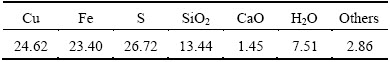
Table 2 Chemical compositions of matte and slag (mass fraction, %)
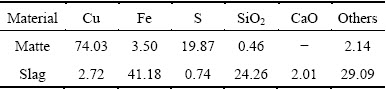

Fig. 2 Gas-liquid interaction in SKS furnace
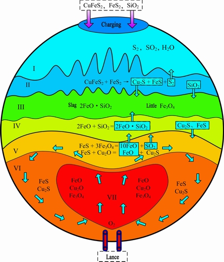
Fig. 3 SKS mechanism model cross section
The multi-phases, multi-components in the SKS furnace are coupled with complicated reactions, mass and heat transfer behaviors, so developing a mechanism model on the SKS process is important to deeply understand the process.
As shown in Fig. 3, our model on the cross section shows that there are four major functional layers, i.e., gas layer, mineral decomposition transitioning layer, major slag layer and matte layer. The major slag layer includes slag layer and slag formation transitioning layer, and the matte layer includes matte formation transitioning layer, weak oxidizing layer and strong oxidizing layer. In general, the cross section of SKS mechanism model could be divided into seven primary layers.

Fig. 4 SKS mechanism model on longitudinal section
3.1.1 Gas layer
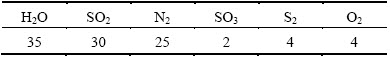
The major compositions in the gas layer are SO2, H2O, N2, S2, volatile components volatile sulfides, oxides and simple substances of Pb, Zn, As, Sb, Bi, Sn etc. and tiny particles of feed materials. Since water content in mixed concentrates is up to 8%-10%, most water is evaporated from the concentrates and enters the gas phase due to high temperature in the furnace. Many other gas components overflow over the melt surface in the form of bubbles. These gases include SO2 generated in the smelting process, N2 brought by air and S2 decomposed from the fed sulfide minerals. This point has been validated that quite quantities of the S2 (about 15% of total S in smelting system [19] ) directly pass into the gas layer in the SKS process. At the same time, a portion of O2 flows over the melt surface, which reacts with S2 according to Eq. (2). In the gas layer, partial volatile sulfide and tiny sulfide particles are also oxidized by O2 as shown in Eq. (3). The main composition of gas just out of SKS furnace without MewOn (metallic oxide) is listed in Table 3.
H2O(l)=H2O(g) (1)
S2(g)+2O2(g)=2SO2(g) (2)
MexSy(g/s)+
 (g/s)+ySO2(g) (3)
Table 3 Main compositions of gas just out of SKS furnace without MewOn (volume fraction, %)
3.1.2 Mineral decomposition transitioning layer
When the fed concentrates fall on the surface of the molten slag at 1200 ��C, most sulfate minerals with high-sulfur content decompose into sulfate minerals with low-sulfur content and S2 gas. The chemical composition of mixed concentrates is listed in Table 1. Chalcopyrite (CuFeS2) is a kind of important copper sulfide mineral, and its ignition temperature is 375 ��C. When the temperature rises up to 550 ��C in neutral or reductive atmosphere, chalcopyrite will start to decompose according to Eq. (4) below, and decomposes completely at 800-1000 ��C. Pyrite (FeS2) is also a major mineral of sulfide ores, and its ignition temperature is 402 ��C. So it is easy to decompose as the temperature rises. At 300 ��C, in neutral or reductive atmosphere, pyrite starts to decompose according to Eq. (5) below. At 1��105 Pa and 565 ��C, it starts to decompose, and the decomposition pressure comes up to 69.061 kPa at 680 ��C.
4CuFeS2(s)=2Cu2S(s)+4FeS(s)+S2(g) (4)
2FeS2(s)=2FeS(s)+S2(g) (5)
Silica in the mixed ore passes through mineral decomposition transitioning layer into slag layer to form slag, and SO2, N2, O2, etc, in melts passes through mineral decomposition transitioning layer into gas layer.
3.1.3 Slag layer
Fayalite (2FeO��SiO2), the major composition of the slag layer, is formed by floating of the low-density fayalite slag from slag formation transitioning layer. At 1200 ��C, the density of slag in the SKS furnace is 3.81 g/cm3, calculated by Eq. (6) [20]. Since matte density is about 5.1 g/cm3, the density difference between slag and matte facilitates the separation of matte from slag. The chemical composition of slag samples is listed in Table 2.
��=5-0.03[w(SiO2)+w(Fe2O3)]-0.02[w(CaO)+w(MgO)+w(Al2O3)+w(Na2O)]+0.035w(Cr2O3)-0.01(T-1200) (g/cm3) (6)
Sulfide phases, such as Cu2S, FeS, CuFeS2, FeS2, etc, transfer downwards quickly, resulting from their density and flow motion.
3.1.4 Slag formation transitioning layer
During the smelting process, FeO passes through the interface of matte formation transitioning layer to the slag formation transitioning layer, and SiO2 also enters the slag formation transitioning layer from the layer above, so slag forming reaction is carried out between FeO and SiO2 as Eq. (7) below.
2FeO(l)+SiO2(s)=2FeO��SiO2(l) (7)
��G=-38291+14.002T (J) (8)
Fayalite (2FeO��SiO2), which is produced by slag forming reaction, passes through the interface and enters the slag layer. SO2, produced in matte layer, passes through the interface quickly. The slag formation transitioning layer is stirred violently by SO2 gas, which greatly accelerates slag forming reactions.
3.1.5 Matte formation transitioning layer
The function of the matte formation transitioning layer is to produce copper matte. The chemical composition of matte samples is listed in Table 2. Since the oxygen is blown from bottom of the furnace, partial matte is oxidized to Cu2O, FeO, Fe3O4, and Fe2O3 by the oxygen-enriched air blown into the strong oxidizing layer. Cu2O is transferred to this layer, and proceeds matte forming reactions with FeS from up layers as Eq. (9).
FeS(l)+Cu2O(l)=FeO(l)+Cu2S(l) (9)
��G=-144750+13.05T (J) (10)
Fe3O4 and Fe2O3 also proceed chemical reactions with FeS, just as Eqs. (11) and (14):
3Fe3O4(s)+FeS(l)=10FeO(l)+SO2(g) (11)
��G=637285-358.1T (J) (12)
 (13)
(13)
10Fe2O3(g)+FeS(l)=7Fe3O4(s)+SO2(g) (14)
��G=223870-354.25T (J) (15)
As shown in Fig. 5, the lowest spontaneous temperatures of reactions (11) and (14) are 1779.63 K (1506.48 ��C) and 631.95 K (358.8 ��C), respectively. The equilibrium constant of reaction (11) is tiny at 1200 ��C, so Fe3O4 is hardly reduced just by FeS. At this point, SiO2 in the slag formation transitioning layer passes through the boundary into the matte formation transitioning layer, captures FeO in the matte formation transitioning layer, and finally form stable 2FeO��SiO2 just as Eq. (16). In this case, reducing the FeO activity promotes the reduction of Fe3O4.
FeS(l)+3Fe3O4(s)+5SiO2(s)=5(2FeO��SiO2)(l)+SO2(g) (16)
��G=220386-153.05T (J) (17)
When the temperature is higher than 1439.96 K (1166.81 ��C), reaction (16) takes place spontaneously, and the reaction equilibrium constant is 31.74 at 1300 ��C. Since the layer is close to the heart of reaction zone with higher temperatures, reaction (16) could promote the reduction of Fe3O4 even further.

Fig. 5 Gibbs free energy of smelting reaction in SKS furnace
3.1.6 Weak oxidizing layer
As shown in Fig. 3, the weak oxidizing layer is quite large in space. The lance blows oxygen-enriched air into this layer from the bottom of the furnace. The air first moves upwards and gradually expands from the inside out, propelling the fluid cycling. The layer is to make components cycling in the reaction zone, and to transmit sulfur-containing components from other layers and regions to strong oxidizing layer to accelerate their oxidation reactions. For instance, FeS and Cu2S pass through the boundary between slag layer, slag formation transitioning layer and matte formation transitioning layer successively into the strong oxidizing layer by the cycling mechanism, and finally mix with the product Cu2S in the matte formation transitioning layer. Abundant heat energy is produced in the strong oxidizing layer, and transferred to other layers and regions by the cycling mechanism. Meanwhile, partial Cu2O, Fe3O4 and Fe2O3, which have not reacted completely in the matte formation transitioning layer, are transferred into the weak oxidizing layer and reduced to Cu2S and FeO. In conclusion, the function of the weak oxidizing layer is to transmit sulfur containing components to the strong oxidizing layer, and transmit heat energy to other outside layers and regions.
3.1.7 Strong oxidizing layer
Oxidizing reaction carries out violently in the strong oxidizing layer. FeS transmitted from the weak oxidizing layer is oxidized and desulfurized, and yields FeO. Even partial FeO is further oxidized and yields Fe3O4 and Fe2O3. Partial Cu2S is also oxidized and yields Cu2O. The oxidation process releases a large amount of heat energy, as following reactions:
2FeS(l)+3O2(g)=2FeO(l)+2SO2(g) (18)
2Cu2S(l)+3O2(g)=2Cu2O(l)+2SO2(g) (19)
6FeO(l)+O2=2Fe3O4(s) (20)
The products Cu2O, FeO, Fe3O4 and Fe2O3 are transferred respectively into other functioning layers to react with other components. The strong oxidizing layer mainly converts partial O2 into oxide MexOy, and transmits element O into other function layers in the form of O2 and MexOy. Abundant heat energy is a product of chemical reactions, and is transferred outside to keep the heat balance of the high temperature melt in the SKS furnace.
3.2 SKS mechanism model on longitudinal section and on mass transfer behavior between multiphase interfaces
As shown in Fig. 4, our SKS mechanism model divides the reactor along length direction into 3 regions: reaction region, separation transitioning region and liquid phase separation and settling region.
3.2.1 Reaction region
The function of the reaction region is basically coincident with the cross section of our model. From top to bottom and from outside to inside, reaction region is divided into seven major functional layers. In this region, the high temperature melt is stirred violently by air with high flow rates. Cu2O, FeO and Fe3O4 generated in the strong oxidizing layer circulate rapidly along the arrow direction under the air-blowing force, and pass through multiphase interfaces quickly. When Cu2O and Fe3O4 are moved into the matte formation transitioning layer, they are reduced and yield Cu2S and FeO, respectively. The FeO further reacts with SiO2, and generates olivine (2FeO��SiO2) which is later transferred into the slag layer. Meanwhile, SO2 generated in the strong oxidizing layer passes through the matte and slag layer into the gas layer, and provides floating power for olivine moving up. Cu2S and FeS generated in mineral decomposition transitioning layer have higher densities than slag, and gradually drop down to the weak-oxidizing layer, and later enter the strong oxidizing layer through the cycling mechanism.
3.2.2 Separation transitioning region
The separation transitioning region mainly plays a transition role between the reaction region and liquid phase settling region. In this region, the stirring wave is reduced gradually, and the melt boundary becomes clear and stable finally. The melt in this region is divided into four layers: slag layer, slag formation transitioning layer, matte formation transitioning layer and weak oxidizing layer. Meanwhile, partial components that do not finish reactions completely in the reaction region may move to this region, and continue the reaction. SO2 micro-bubbles merge together, and gradually pass through the boundary interface and move into gas layer.
3.2.3 Liquid phase separation and settling region
The liquid phase separation and settling region is at other end of the SKS furnace with matte and slag tap ports. The melt waves slightly. The slag layer is on the top and the copper matte layer is on the bottom. Oxygen potential in this region is lower than that of other two regions, and all metallurgical reactions are almost completed. The liquid matte and slag are gradually separated and settled down. The matte micro-droplets in slag aggregate and grow. Bigger droplets fall down, pass through the slag-matte interface and come to the matte layer. Iron silicon slag micro-droplets in the matte layer also aggregate and grow, float upward, pass through the slag-matte interface and come to the slag layer. Weak fluctuations could provide power for matte droplets dropping and slag droplets floating, and promote matte-slag separations.
3.3 Changing trend of sulfur-oxygen potential in SKS furnace and its influence on smelting process
Matte and slag phases in SKS process are both in the state of heterogeneous and unsteady phase- equilibrium, and reaction mass transfer model of O and S elements is shown in Fig. 6.
When the concentrates fall into the SKS furnace, most high-sulfur minerals (CuFeS2, FeS2, etc.) decompose into low-sulfur minerals (Cu2S, FeS, etc.) and S2 gas. Partial FeS and S2 are further oxidized and yield SO2 gas. Most S element enters the matte phase. O element of O2 blown through lances reacts with sulfates and yields SO2 gas and FeO. The FeO continues reacting with silica, and generates olive slag that leads to O element to be locked in 2FeO��SO2.
The SKS process is at a multiphase non-steady state equilibrium of the gas-slag-matte coexistence system. The system is far from equilibrium with continuous feeding, oxygen injection, slag and matte tapping. And the oxygen and sulfur potentials change gradually in different locations of the furnace. The distribution of oxygen and sulfur potentials in the SKS furnace has important impact on yielding Fe3O4, which affects the slag properties such as viscosity etc., and finally affects copper losses in the slag. Meanwhile, the oxygen and sulfur potentials also affect the reaction thermodynamic equilibrium significantly. The average operating temperature of the SKS smelting process is about 1200 ��C. By analyzing sulfur-oxygen potential diagram for Cu-Fe-S-O-SiO2 system and phase equilibrium status at 1200 ��C [21], the sulfur-oxygen potential of the strong oxidizing zone, mineral decomposition zone and smelting equilibrium can be determined qualitatively, just as shown in Fig. 7.
In production practice, the process could be optimized by best controlling the sulfur-oxygen potentials in different layers and regions, and by optimizing some other operating parameters, such as oxygen enriched concentration, oxygen blowing rate, ore feeding rate and cold materials blending ratio. Finally, the capacity of the SKS process can be raised by measures mentioned above, and at the same time the Fe3O4 content in the slag can be controlled in a lower level.
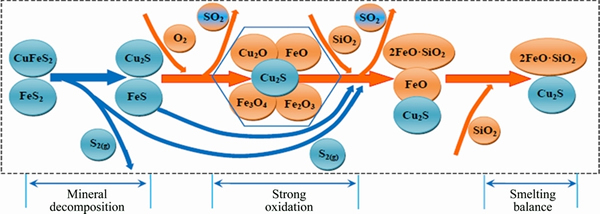
Fig. 6 Reaction mass transfer model of O and S elements in SKS process
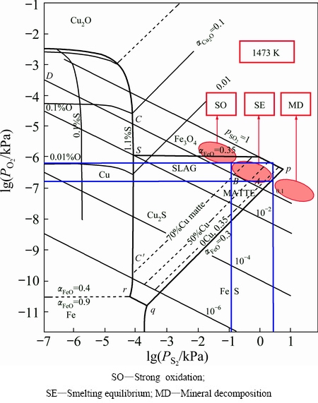
Fig. 7 Sulfur-oxygen potential diagram for Cu-Fe-S-O-SiO2 system of SKS process at 1473 K
4 Conclusions
1) The SKS mechanism model on the cross section of the furnace is divided into four major functional layers, i.e. gas layer, mineral decomposition transitioning layer, major slag layer and matte layer. Meanwhile, major slag layer contains slag layer and slag formation transitioning layer, and matte layer contains matte formation transitioning layer, weak oxidizing layer and strong oxidizing layer. So, the cross section of the SKS mechanism model is divided into seven subprime layers. These layers play different roles and together constitute an organic unit. Ploycomponent, such as CuFeS2, FeS2, Cu2S, FeS, 2FeO��SiO2, Cu2O, FeO, Fe3O4, SO2, H2O, N2 and S2, passes quickly through interfaces of different layers and regions due to the character differentiation and the effect of fluid flowing in the system.
2) The SKS mechanism model on horizontal direction is divided into reaction region, separation transitioning region, liquid phase separation and settling region, and further can be divided into seven, five and three subprime layers, respectively. From reaction region to liquid phase separation and settling region, melt mixing waves weaken gradually, and the process of matte separating from slag is gradually completed.
3) The SKS process is at a dynamic multiphase non-steady state of gas-slag-matte coexistence system which is far from equilibrium due to continuous feeding, oxygen injecting, slag and matte tapping. And the oxygen and sulfur potentials change gradually in different locations of furnace. The capacity of the SKS furnace could be raised by reasonably controlling the potential values in different layers and regions.
References
[1] GUO Xue-yi, SONG Yu. Substance flow analysis of copper in China [J]. Resources, Conservation & Recycling, 2008, 52(6): 874-882.
[2] WANG Qin-meng, GUO Xue-yi, TIAN Qing-hua, LIAO Li-le, ZHANG Yong-zhu. Multicomponent slagging behavior and constitution optimization of slag in copper oxygen bottom blowing bath smelting process [J]. The Chinese Journal of Nonferrous Metals, 2015, 25(6): 1678-1686. (in Chinese)
[3] WANG Qin-meng, GUO Xue-yi, LIAO Li-le, TIAN Qing-hua, ZHANG Yong-zhu. Multicomponent matte formating behavior and content mapping relationship in copper oxygen bottom blowing bath smelting process [J]. The Chinese Journal of Nonferrous Metals, 2016, 26(1): 188-196. (in Chinese)
[4] LI Wei-feng, JIANG Lihua, ZHAN Jing, ZHANG Chuanfu, LI Gui, HUANG Jian-yang. Thermodynamics analysis and industrial trials of bottom-blowing smelting for processing lead sulfate-containing materials [C]//Proceedings of the International Symposium on High-Temperature Metallurgy Processing. San Antonio: John Wiley & Sons, Inc., 2015: 507-514.
[5] LI Chun-tang. Oxygen bottom blowing technology by three continuous furnaces is the world's top copper metallurgy process [N]. China Nonferrous Metals News, 2009, 7: 11(008). (in Chinese)
[6] LIU Wei, LUO Hong-lin, QING Wen-qing, ZHENG Yong-xing, YANG Kang, HAN Jun-wei. Investigation into oxygen-enriched bottom-blown stibnite and direct reduction [J]. Metallurgical and Materials Transactions B, 2014, 45(4): 1281-1290.
[7] CUI Zhi-xiang, SHEN Dian-bang, WANG Zhi, LI Wei-qun, BIAN Rui-min. New process of copper smelting with oxygen enriched bottom blowing technology [J]. Nonferrous Metals (Extractive Metallurgy), 2010(3): 17-20. (in Chinese)
[8] GUO Xue-yi, WANG Qin-meng, TIAN Qing-hua, ZHAO Bao-jun. Analysis and optimization of oxygen bottom blowing copper smelting process [J]. The Chinese Journal of Nonferrous Metals, 2016, 26(3): 689-698. (in Chinese)
[9] YAZAWA A. Thermodynamic considerations of copper smelting [J]. Canadian Metallurgical Quarterly, 1974, 13(3): 443-453.
[10] SERGEI A D, ARTHUR D P. A thermodynamic database for copper smelting and converting [J]. Metallurgical and Materials Transactions B, 1999, 30(4): 661-669.
[11] SRIDHAR R, TOGURI J M, SIMEONOV S. Copper losses and thermodynamic considerations in copper smelting [J]. Metallurgical and Materials Transactions B, 1997, 28(2): 191-200.
[12] NAGAMORI M, MACKEY P J. Thermodynamics of copper matte converting: Part 1. Fundamentals of the Noranda process [J]. Metallurgical and Materials Transactions B, 1978, 9(3): 255-265.
[13] MACKEY P J. The physical chemistry of copper smelting slags��A review [J]. Canadian Metallurgical Quarterly, 1982, 21(3): 221-260.
[14] ZHANG Zhen-yang, CHEN Zhu, YAN Hong-jie, LIU Fang-kan, LIU Liu, CUI Zhi-xian, SHEN Dian-ban. Numerical simulation of gas-liquid multi-phase flows in oxygen enriched bottom-blown furnace [J]. The Chinese Journal of Nonferrous Metals, 2012, 22(6): 1826-1834. (in Chinese)
[15] ZHANG Zhen-yang, YAN Hong-jie, LIU Fang-kan, WANG Ji-min. Optimization analysis of lance structure parameters in oxygen enriched bottom-blown furnace [J]. The Chinese Journal of Nonferrous Metals, 2013, 23(5): 1471-1477. (in Chinese)
[16] CHEN Mao, CUI Zhi-xiang, ZHAO Bao-jun. Slag chemistry of bottom blown copper smelting furnace at Dongying Fangyuan [C]//Proceedings of the 6th International Symposium on High-temperature Metallurgical Processing. Orlando, FL, USA: The Minerals, Metals & Materials Society, 2015: 257-264.
[17] CUI Zhi-xiang, SHEN Dian-bang, WANG Zhi, BIAN Rui-min. Low-carbon economy and new process of copper smelting with oxygen enriched bottom blowing technology [J]. Energy Saving on Technique, 2011(1): 17-20. (in Chinese)
[18] QU Sheng-li, DONG Zhun-qin, CHEN Tao. Study on gold collection in matte with oxygen enriched bottom blowing smelting process [J]. Nonferrous Metals (Extractive Metallurgy), 2013(6): 40-42. (in Chinese)
[19] LIAO Li-le. Development and application of simulation platform in the oxygen bottom blowing copper smelting process [D]. Changsha: School of Metallurgy and Environment, Central South University, 2016: 21-23. (in Chinese)
[20] ZHU Zu-ze, HE Jia-qi. Current copper metallurgy [M]. Beijing: Science Press, 2003: 320-322. (in Chinese)
[21] YAZAWA A. Thermodynamic evaluation of extractive metallurgical process [J]. Metallurgical Transactions B, 1979, 10(3): 307-321.
�����״���ͭ����
�����ͣ���ѧ�棬���컪
���ϴ�ѧ ұ���뻷��ѧԺ����ɳ 410083
ժ Ҫ�������״�¯��һ������ŵ����¯����ʽ��ת��Ӧ����������������¯��ײ��������塣ͨ�������״��������ԣ�����������״���ͭ�������ڻ���ģ���У��״�¯�����ϵ��·ֳ�7�����ܲ㣬�ֱ��������㡢���Ϸֽ���ɲ㡢���㡢�������ɲ㡢��ﳹ��ɲ㡢���������ǿ�����㣻�����߷���ֳ�3�����������ֱ��Ƿ�Ӧ���������������Һ���������ģ�������еIJ�����ֱ���в�ͬ�����á������״��������̴��ڷ���̬�Ľ��ƶ���ƽ��״̬����¯�ڲ�ͬ�ռ�λ������ơ����Ƴ��ݶȱ仯��ͨ���������Ʋ�ͬ�㡢�������ơ����ƣ��ɽ�һ����������״�¯������������
�ؼ��ʣ������״���ͭ������������ƽ�⣻���ƣ����ƣ�SKS����
(Edited by Yun-bin HE)
Foundation item: Project (51620105013) supported by the National Natural Science Foundation of China
Corresponding author: Xue-yi GUO; Tel: +86-731-88877863; E-mail: xyguo@csu.edu.cn
DOI: 10.1016/S1003-6326(17)60110-9
Abstract: The SKS furnace is a horizontal cylindrical reactor similar to a Noranda furnace, however, the oxygen enriched air is blown into the furnace from the bottom. Mechanism model of the SKS process was developed by analyzing the smelting characteristics deeply. In our model, the furnace section from top to bottom is divided into seven functional layers, i.e., gas layer, mineral decomposition transitioning layer, slag layer, slag formation transitioning layer, matte formation transitioning layer, weak oxidizing layer and strong oxidizing layer. The furnace along the length direction is divided into three functional regions, that is, reaction region, separation transitioning region and liquid phase separation and settling region. These layers or regions play different roles in the model in describing the mechanism of the smelting process. The SKS smelting is at a multiphase non-steady equilibrium state, and the oxygen and sulfur potentials change gradually in the length and cross directions. The smelting capacity of the SKS process could be raised through reasonably controlling the potential values in different layers and regions.
