

J. Cent. South Univ. (2018) 25: 2615-2625
DOI: https://doi.org/10.1007/s11771-018-3940-3

Robust control with compensation of adaptive model for dual-stage inertially stabilized platform
SONG Jiang-peng(�ν���)1, 2, ZHOU Di(��ݶ)1, SUN Guang-li(�����)2, QI Zhi-hui(���ǻ�)2
1. Department of Control Science and Engineering, Harbin Institute of Technology, Harbin 150001, China;
2. Tianjin Jinhang Institute of Technical Physics, Tianjin 300192, China
 Central South University Press and Springer-Verlag GmbH Germany, part of Springer Nature 2018
Abstract:
To achieve excellent tracking accuracy, a coarse-fine dual-stage control system is chosen for inertially stabilized platform. The coarse stage is a conventional inertially stabilized platform, and the fine stage is a secondary servo mechanism to control lens motion in the imaging optical path. Firstly, the dual-stage dynamics is mathematically modeled as a coupling multi-input multi-output (MIMO) control system. Then, by incorporating compensation of adaptive model to deal with parameter variations and nonlinearity, a systematic robust H�� control scheme is designed, which can achieve good tracking performance, as well as improve system robustness against model uncertainties. Lyapunov stability analysis confirmed the stability of the overall control system. Finally, simulation and experiment results are provided to demonstrate the feasibility and effectiveness of the proposed control design method.
Key words:
dual-stage control; inertially stabilized platform; robust H�� control; adaptive model��
Cite this article as:
SONG Jiang-peng, ZHOU Di, SUN Guang-li, QI Zhi-hui. Robust control with compensation of adaptive model for dual-stage inertially stabilized platform [J]. Journal of Central South University, 2018, 25(11): 2615�C2625.
DOI:https://dx.doi.org/https://doi.org/10.1007/s11771-018-3940-31 Introduction
Inertially stabilized platforms are used to achieve the line of sight (LOS) of the optical sensors controlled motion on the moving platforms or ground-mounted devices. Typically, a conventional inertially stabilized platform consists of two orthogonal gimbals to control the inertial orientation of the optical sensors [1, 2].
In the past decade, the dual-stage control system has been successfully applied to improving control performance in the field of hard disk drives [3�C7]. Enlightened by these applications, a dual- stage stabilized platform has been paid attention recently, which can provide similar control capability without increasing the shape and size [8].
There are many research works for the design of dual-stage controller. RYOO et al [9] proposed a dual-stage PQ controller to simplify the controller design into two single-input single-output (SISO) control problems. KOGANEZAWA et al [10] used the master slave controller structure in the dual-stage system to deal with the coupling disturbance. RAYMOND et al [11] summarized the application of modern control techniques such as adaptive control, LQG/LTR technique and robust control technique in the dual-stage control system. CHAO et al [12] successfully applied robust H�� technique to achieve high precision control and robustness for a dual- stage control system. HUANG et al [13] proposed a robust mixed H2/H�� controller to enhance the tracking performance and stability robustness of a dual-stage servo system.CHEN et al [14] proposed an adaptive fuzzy H�� control method to reduce the effect of the model error and external disturbance.
Note that, robust H�� controller is usually conservative due to model uncertainties and other nonlinearities. It is beneficial to combine with some nonlinear compensation technique, such as friction disturbance compensation, to further improve the control performance of H�� control [15�C20]. For example, a robust ��-synthesis controller combined with adaptive model compensation technique has been used in the linear motor systems to overcome the effect of nonlinearities [21].
In this paper, a robust H�� MIMO controller with compensation of adaptive model is proposed for the dual-stage stabilized platform. It can effectively improve the tracking performance and guarantee overall system stability. Firstly, the dynamic mode of the dual-stage control system is derived. Then a robust H�� control scheme with compensation of adaptive model is designed. By incorporating compensation of adaptive model, the proposed controller can effectively attenuate the effect of model errors and system nonlinearities, such as friction nonlinearity. Finally, stability of the proposed dual-stage robust controller is proved by means of Lyapunov theory.
The remainder of this paper is organized as follows. In Section 2, the dynamic model is derived and the system parameters are given by system identification experiment. In Section 3, a systematic control scheme using a robust H�� controller with compensation of adaptive model is developed. In Section 4, simulation and experiment are carried out to verify the effectiveness of the proposed controller. Finally, some conclusions are summarized in Section 5.
2 Plant model and identification
The dual-stage stabilized platform studied in this paper is composed with the coarse stage and the fine stage. The fine stage is placed in the imaging optical path to control lens motion as the micro- scan lens (MSL).
2.1 MSL model
MSL mechanical structure is shown in Figure 1. It can be seen that the flexure hinge is used to amplify and transmit the voice coil motor (VCM) displacement without the bearing [22].
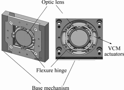
Figure 1 Mechanical structure of MSL
Therefore, the dynamic model of the MSL is simplified as a mass�Cspring�Cdamper system model, as shown in Figure 2.
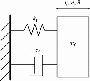
Figure 2 Simplified linear dynamic model of MSL
The linear dynamic model of MSL can be expressed as

 (1)
(1)
where uf is the input voltage; �� is the translation displacement; mf, cf and kf represent the equivalent mass, damping coefficient and stiffness respectively; L is the distance between the gimbal rotation axis and the VCM actuator position; �� and  represent the gimbal angle and gimbal velocity respectively; df is the lumped external disturbances in the MSL.
In order to improve the damping effect of the MSL, the inner loop damping controller of MSL is designed by using the embedded displacement transducer before the dual-stage controller design. The damping closed-loop dynamics of MSL can be expressed as

 (2)
(2)
where ��f, ��f and Af are the natural frequency, the damping ratio and the equivalent gain, respectively;  is the equivalent lumped external disturbances in the MSL.
The system parameters ��f, ��f and Af of the MSL can be obtained from the frequency response of the damping MSL as


 (3)
(3)
The high-frequency model is susceptible to the product manufacture tolerance and measurement error, since it is treated as unstructured uncertainty. The friction of the MSL is assumed to have slight influence because of the flexure hinge mechanism.
2.2 Two-axis gimbal platform model
A two-axis inertially stabilized platform is shown in Figure 3.
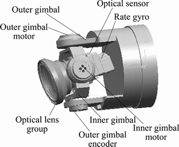
Figure 3 Structure of a two-axis gimbal configuration
It can be seen that this two-axis gimbal platform mainly consists of DC torque motor, encoder, optical sensor and a two-axis rate gyro, which is used to measure the inertial angular rates.
The gimbal dynamics can be represented in the following form:
 (4)
(4)
where is the inertial angular rate; Mmy is gimbal motor torque; dfy is gimbal nonlinear friction torque; duy is the mass imbalance torquel; dcry is the cable restraint torque; dy _cross is the cross coupling torque and Js is the equivalent moment of inertia.
Then, the corresponding outer gimbal state space model can be written as

 (5)
(5)
where umy denotes control voltage input; R denotes the resistance of motor armature windings; dly denotes other lumped unknown disturbances including duy, dcry, dy_cross; the scalars Ke and Kt are the back EMF constant and the motor force constant, respectively.
From Eq. (5), dfy is a nonlinear friction torque which can be described by a nonlinear static coulomb friction model, i.e.,
 (6)
(6)
where Bfy is the viscous friction coefficient; Afy is the coulomb friction coefficient; is the gimbal relative angular velocity;
 is the signum function about.
The system parameters Js, Kt, Ke, R and the friction parameters Afy, Bfy can be obtained by the system identification technique as

 (7)
(7)
Similar to the MSL, the high-frequency gimbal model is treated as unstructured uncertainty.
The gimbal is susceptible to nonlinear friction and other nonlinearities. If these nonlinearities are treated as unstructured uncertainty, the controller will be too conservative, so the compensation of adaptive model is introduced to deal with these nonlinearities.
2.3 Dual-stage platform model
In the dual-stage platform, MSL is mounted on the two-axis gimbal platform. Based on the dynamic model mentioned above, the dual-stage platform dynamic model can be derived as follows, ignoring unstructured uncertainty.


 (8)
(8)
From Eq. (8), it can be seen that the gimbal dynamics will affect the MSL dynamics through the coupling term 
The structure of the dual-stage system is illustrated in Figure 4.
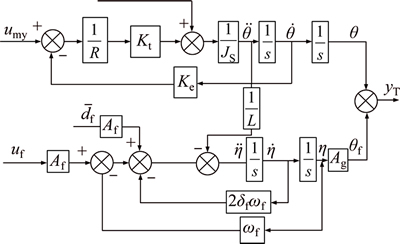
Figure 4 Structure of dual-stage control system
From Figure 4, the angular position �� is the LOS angular output caused by gimbal motion and ��f is the LOS angular output caused by MSL translation displacement; Ag is the relationship between the LOS angular output and MSL translation displacement, which is determined by imaging optical properties. The output angular yT is the combination of the gimbal output �� and the VCM output ��f.
Based on the above description, this dual-stage control system can be regarded as a coupled MIMO system with nonlinearities and external disturbance. It is natural to employ a multi-objective H�� optimal approach to design a dual-stage controller.
Meanwhile, the compensation of adaptive model is suitable for this control system to deal with model uncertainties, such as model errors, parameter variations, nonlinear friction and other nonlinearities.
In the controller design, the coupling term  can be considered an external disturbance.
Define variation parameter sets as ��yu=kt/JSR,  Afy/Js,


 , in which
 can be considered the constant nominal value of the lumped uncertainties dly,
Then Eq. (8) can be rewritten as

 (9)
(9)
where the time-varying portions of 
 are denoted as


2.4 Problem formulation
The following reasonable and practical assumptions are made.
Assumption 1: The variation parameter sets 

 and ��fu are within a known bounded convex set, and the boundary set is assumed to be known from experiment results.
Assumption 2: The disturbance terms are bounded and satisfied 


 where ��dy and ��df are the known bounding function.
Assumption 3: All the states and commands of system are bounded and second-order differentiable for the controller design.
Therefore, under assumptions 1�C3, the control problem for this dual-stage control system can be described as follows.
1) Design a dual-stage robust H�� controller to achieve the specified system performance and guaranteed robustness.
2) The compensation of adaptive model is introduced into the controller design to reduce the effect of model uncertainties and system nonlinearity.
3) The stability of the control scheme, integrating robust H�� technique and compensation of adaptive model can be proved by means of Lyapunov method.
3 Controller design and stability analysis
A basic control architecture for dual-stage servo control system shown in Figure 5 is employed in this paper. From this figure, it can be seen that the output of the VCM fine stage is added to the input of the gimbal coarse stage, which restricts the VCM channel motion and guarantees the output of the VCM on the center of its stroke.
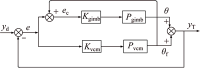
Figure 5 Block diagram of dual-stage platform
where e is the angular position tracking error of the overall system; ec is the angular position tracking error of gimbal coarse stage; yd is reference angular position input of the system; Pgimb and Pvcm are the nominal plants of the coarse gimbal stage and fine VCM stage, respectively; Kgimb and Kvcm are the designed controllers respectively. The notations, such as yT, �� and ��f, are used in Figure 4.
Based on the control architecture shown in Figure 5, a robust H�� controller with compensation of adaptive model will be developed in this section.
3.1 Adaptive model compensation
1) Define tracking errors as
 (10)
(10)
 (11)
(11)
2) Then define the state vector as
 (12)
(12)
3) With Eqs. (10), Eq. (11) and Eq. (12), the state space equation of tracking error x can be written as
 (13)
(13)
where 


4) The controller is designed as
 ,
,  (14)
(14)
where
 (15)
(15)
 (16)
(16)
are the compensation term of adaptive model; 

 and
and are the adaptive estimation parameters. And umys, ufs are the robust control law to be designed using robust H�� design approach.
5) The adaptation laws are designed as

 (17)
(17)

 (18)
(18)
where ��y, ��yu, ��f and ��fu are the positive definite matrices, and ��y, ��yu, ��f and ��fu are adaptive estimation functions. The projection mapping proj(��) is defined as
 (19)
(19)
where ��max and ��min represent the maximum and minimum boundaries of the adaptive estimation parameters respectively.
5) Combining Eq. (13) with Eq. (14), the state space equation becomes
 (20)
(20)
where


and


3.2 Robust H�� controller design
With compensation of adaptive model, the control problem for this dual-stage control system is converted into the standard robust H�� design problem based on the state space Eq. (20). The H�� control structure is given in Figure 6.
The augmentation state space equation can be represented in the following form:
 (21)
(21)
where


The weighting transfer function W1 is chosen based on the unstructured additive uncertainty; W2 is chosen to shape the sensitivity function in order to achieve the specified control accuracy and disturbance attenuation ability. The choice of these weighting transfer functions is detailed as follows.
The model uncertainty such as the high- frequency dynamics is treated as unstructured uncertainty, which can be represented by an additive weighting transfer function W1.
The weighting transfer function W1 consists of gimbal weighting transfer function WG and MSL weighting transfer function Wm. WG mainly reflects the neglected and unmodeled gimbal high- frequency dynamics, and Wm mainly reflects the neglected and unmodeled MSL high-frequency dynamics. WG and Wm can be obtained by the following equations.
 (22)
(22)
where GGnom(s) and GMnom(s) are the nominal reduced order models of the gimbal and MSL, respectively. GGnom(s) and GMnom(s) can be obtained by Eq. (3) and Eq. (7). GG(s) and GM(s) represent the actual system models without neglecting high- frequency dynamics, which can be obtained through system frequency identification results. ��G(s) and ��M(s) are normalized such that ||��G(s)||��1, ||��M(s)||��1.
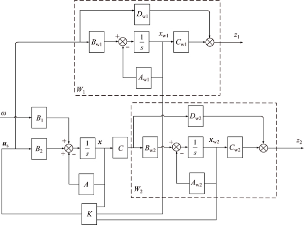
Figure 6 H�� control structure of dual-stage platform
Thus, based on Eq. (22), the weighting transfer functions WG and WM can be captured as


The performance weighting transfer function W2 is usually designed to meet system sensitivity function requirements. In order to guarantee good tracking performance at the concerned low frequencies, a simple low pass filter is chosen to obtain the desired performance weighting transfer function W2 [23]:
 (23)
(23)
where Ms is the upper bound on the magnitude of sensitivity function in all frequencies; ��b is chosen to achieve approximately the desired crossover frequency of sensitivity function; A is a non-zero small number to approximate the integral part of the filter.
Based on Eq. (23) and practical control requirements of this dual-stage control system, W2 is chosen as

where Ms=1.5, ��b=50.24 rad/s, A=0.01.
In general, H�� control problem requires the solutions of two Riccati equations, the state equation and the observer equations [24]. This general H�� control problem is often called H�� output feedback control problem.
In this paper, due to the robust H�� control law us=Kxe, the general H�� control problem can be converted into H�� stage feedback control problem, and the full state feedback is available. This special H�� state feedback controller K can be derived by solving a single Riccati equation rather than two Riccati equations [25]:
 (24)
(24)
where is the solution of the above algebraic Riccati equation.
With the algebraic Riccati solution P, the state feedback controller K is written as
 (25)
(25)
3.3 Stability analysis by means of Lyapunov function
Theorem 1: In the state space Eq. (21), the adaptive estimation functions are chosen as 


 . Then under Assumptions 1�C3, the following results can be obtained:
1) The H�� tracking performance is guaranteed as follows:

 (26)
(26)
where 
 and
and 

2) All state vectors in the state space Eq. (21) are bounded. Furthermore, the Lyapunov function Vs is bounded by
 (27)
(27)
Proof: The Lyapunov function is defined as


Its derivative with respect to time is given by


 (28)
(28)
The derivative of Vs is rewritten with the Riccati Eq. (24) as


 (29)
(29)
where
Integrating with time t=0 to T yields
 (30)
(30)
Since  the above inequation becomes
 (31)
(31)
This proves the situation 1) of Theorem 1.
Now consider the situation 2) of Theorem 1.
Assumption 4: The estimation errors 

 and
and  are bounded within known boundaries by projection mapping proj(��). Thus, it is reasonable to assume
 Mf=
Mf= and
and 
Then, Eq. (29) can be derived as


 (32)
(32)
where
 ��max(��) and ��min(��) are the maximum and minimum eigenvalue of the matrix
 , respectively.
Thus by comparison lemma, part B is proved.
4 Simulation and experiment analysis
4.1 Simulation analysis and results
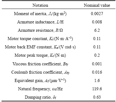
The simulation parameters of the dual-stage platform are obtained from a prototype identified results, as listed in Table 1.
Table 1 System parameters of real platform
The frequency response of the closed-loop control system is given in Figure 7. The results in Figure 7 show that the coarse stage has been limited in the low frequency region below 27 Hz. The overall closed-loop bandwidth of dual-stage system can reach up to 104 Hz.
Here, the proposed robust H�� controller with compensation of adaptive model is abbreviated as AH�� controller. For performance comparison, a conventional H�� controller is also designed to have similar closed loop bandwidth around 104 Hz with AH�� controller.
In order to verify the control performance of the proposed controller, three typical simulation conditions are introduced to compare the tracking performances of the two controllers mentioned above.
Case 1: To verify the trajectory tracking performance of this dual-stage platform, the reference input of system is chosen as the sinusoidal motion with 5��/0.3 Hz.
Case 2: To verify the performance under external disturbance, a sinusoidal motion with 2��/2 Hz is introduced as external disturbance and the dual-stage platform is controlled by the proposed controller.
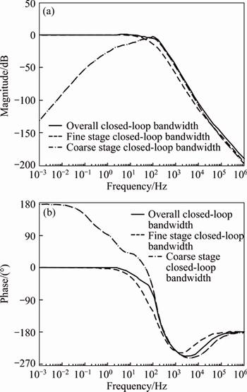
Figure 7 Simulated bode diagram of dual-stage control system
Case 3: To verify the adaptive estimation performance of the controlled system to parameter variations, set the coulomb friction coefficient fluctuation to be 10%, while the external disturbance is chosen as the sinusoidal motion with 2��/2 Hz.
The simulation results under Case 1 are shown in Figure 8. The results show that the maximum tracking error of AH�� is 0.011�� while the maximum tracking error of conventional H�� is 0.041��.
The simulation results under Case 2 are shown in Figure 9. The maximum position tracking error of AH�� is 0.012�� while the maximum position tracking error of conventional H�� is 0.042��. These results reflect the effectiveness of the proposed controller to overcome external disturbance.
The simulation results under Case 3 are shown in Figures 10 and 11. It is obvious that the tracking error becomes smaller after several periods due to the compensation of adaptive model with converging online coulomb friction coefficient estimate.
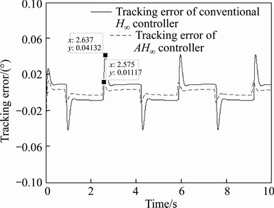
Figure 8 Position tracking errors with AH�� and H�� under Case1
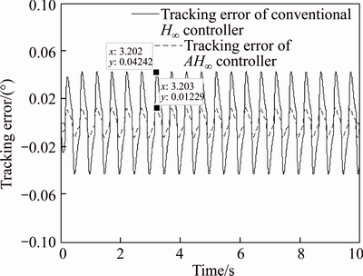
Figure 9 Position tracking errors with AH�� and H�� under Case 2
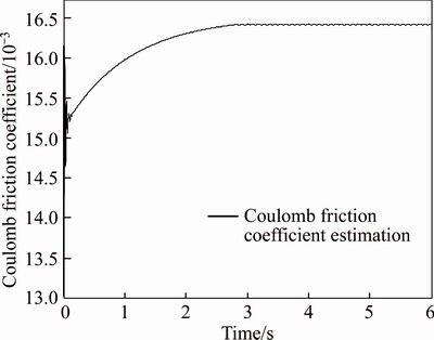
Figure 10 Parameter estimation of coulomb friction coefficient
4.2 Experiment analysis and results
The proposed controller has been also verified in the prototype to further assess its feasibility. The hardware setup is shown in Figure 12.
In the experiment, this dual-stage platform is mounted on a flight simulation table which is controlled by the sinusoidal motion with 2��/2 Hz as external disturbance caused by the base motions.
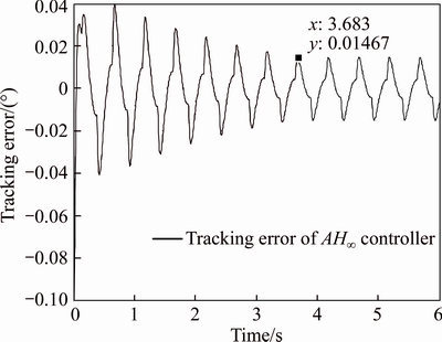
Figure 11 Position tracking errors under Case 3
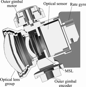
Figure 12 Structure of mirror stabilization platforms
The results in Figure 13 show that the maximum tracking error of AH�� is 0.012��while the maximum tracking error of conventional H�� is 0.041��.
It is clear that the simulation and experiment results are very similar. The slight difference is mainly due to some model errors, such as the friction model.
5 Conclusions
In this paper, a dual-stage H�� controller with compensation of adaptive model is designed. The compensation of adaptive model is used to deal with the nonlinearity dynamics, such as friction nonlinearity, and the H�� state feedback controller is developed to achieve the specified system performance, such as the tracking accuracy and robustness. Stability of the closed-loop system is proved by means of Lyapunov analysis.
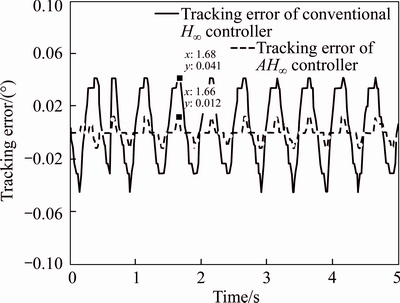
Figure 13 Position tracking error in experiment under external disturbance
Simulation and experiment results show that the proposed controller can obtain satisfactory tracking performance and disturbance rejection performance, which is superior to the conventional H�� controller. With the proposed controller��the maximum position tracking error is reduced to 0.012�� under the condition of external disturbance.
Future work will include experiment verification of the proposed controller in handling the effects of parameter variations and model uncertainties.
References
[1] HILKERT J M. Inertially stabilized platform technology Concepts and principles [J]. IEEE Control Systems, 2008, 28(1): 26�C46. DOI:10.1109/MCS.2007.910256.
[2] MASTEN M K. Inertially stabilized platforms for optical imaging systems [J]. Control Systems IEEE, 2008, 28(1): 47�C64. DOI:10.1109/MCS.2007.910201.
[3] MORI K, MUNEMOTO T, OTSUKI H, YAMAGUCHI Y. A dual-stage magnetic disk drive actuator using a piezoelectric device for a high track density [J]. IEEE Transactions on Magnetics, 1991, 27(6): 5298�C5300. DOI:10.1109/20.278818.
[4] LI Y, HOROWITZ R. Mechatronics of electrostatic microactuators for computer disk drive dual-stage servo systems [J]. IEEE/ASME Transactions on Mechatronics, 2001, 6(2): 111�C121. DOI:10.1109/3516.928724.
[5] KOBAYASHI M, HOROWITZ R. Track seek control for hard disk dual-stage servo systems [J]. IEEE Transactions on Magnetics, 2001, 37(2): 949�C954. DOI:10.1109/ 20.917648.
[6] GUO G, HAO Q, LOW T S. A dual-stage control design for high track per inch hard disk drives [J]. IEEE Transactions on Magnetics, 2001, 37(2): 860�C865. DOI:10.1109/ 20.917632.
[7] KOGANEZAWA S, UEMATSU Y, YAMADA T, NAKANO B. Dual-stage actuator system for magnetic disk drives using a shear mode piezoelectric microactuator [J]. IEEE Transactions on Magnetics, 1999, 35(2): 988�C992. DOI: 10.1109/20.753821.
[8] LYOU J, KANG M S, KWAK H K, CHOI Y J. Dual stage and an image processing-based method for sight stabilization [J]. Journal of Mechanical Science & Technology, 2009, 23(8): 2097�C2106. DOI:10.1007/s12206-009-0356-x.
[9] RYOO J R, DOH T Y, CHUNG M J. Compensator design for a dual-stage actuator in the track-following servo system of optical disk drives [J]. IEEE Transactions on Consumer Electronics, 2004, 51(2): 471�C477. DOI: 10.1109/TCE. 2005.1467989.
[10] KOGANEZAWA S, UEMATSU Y, YAMADA T, NAKANO H. Dual-stage actuator system for magnetic disk drives using a shear mode piezoelectric microactuator [J]. IEEE Transactions on Magnetics, 1999, 35(2): 988�C992. DOI: 10.1109/20.753821.
[11] CALLAFON R A D, NAGAMUNE R, HOROWITZ R. Robust dynamic modeling and control of dual-stage actuators [J]. IEEE Transactions on Magnetics, 2006, 42(2): 247�C254. DOI:10.1109/TMAG.2005.861738.
[12] CHAO C P, LIAO L D, LIN H H, CHUNG M H. Robust dual-stage and repetitive control designs for an optical pickup with parallel cantilever beams powered by piezo-actuation [J]. Microsystem Technologies, 2010, 16(1, 2): 317�C331. DOI: 10.1007/s00542-009-0909-z.
[13] HUANG X, HOROWITZ R. Robust controller design of a dual-stage disk drive servo system with an instrumented suspension [J]. IEEE Transactions on Magnetics, 2005, 41(8): 2406�C2413. DOI:10.1109/TMAG.2005.852179.
[14] CHEN B S, LEE C H, CHANG Y C. H�� tracking design of uncertain nonlinear SISO systems: adaptive fuzzy approach [J]. Fuzzy Systems IEEE Transactions on, 1996, 4(1): 32�C43. DOI: 10.1109/91.481843.
[15] CHEN S L, TAN K K, HUANG S, TEO C S. Modeling and compensation of ripples and friction in permanent-magnet linear motor using a hysteretic relay [J]. IEEE/ASME Transactions on Mechatronics, 2010, 15(4): 586�C594. DOI: 10.1109/TMECH.2009.2030794.
[16] LIN C J, YAU H T, TIAN Y C. Identification and compensation of nonlinear friction characteristics and precision control for a linear motor stage [J]. IEEE/ASME Transactions on Mechatronics, 2013, 18(4): 1385�C1396. DOI: 10.1109/TMECH.2012.2202679.
[17] LU Lu, BIN Yao, WANG Qing-feng, CHEN Zheng. Adaptive robust control of linear motor systems with dynamic friction compensation using modified LuGre model [J]. Automatica, 2009, 45(12): 2890�C2896. DOI: 10.1109/AIM.2008. 4601791.
[18] CHEN Z, YAO B, WANG Q. Accurate motion control of linear motors with adaptive robust compensation of nonlinear electromagnetic field effect [J]. IEEE/ASME Transactions on Mechatronics, 2013, 18(3): 1122�C1129. DOI: 10.1109/TMECH.2012.2197217.
[19] LI Bing, WU Jun-feng, HUANG Ling. Improved H_�� control for networked control systems with network-induced delay and packet dropout [J]. Journal of Central South University, 2016, 23(5): 1215�C1223. DOI: 10.1007/s11771- 016-0371-x.
[20] REN Li-tong, XIE Shou-sheng, MIAO Zhuo-guang. Fuzzy robust sliding mode control of a class of uncertain systems [J]. Journal of Central South University, 2016, 23(9): 2296�C2304. DOI: 10.1007/s11771-016-3287-6.
[21] CHEN Z, YAO B, WANG Q. ��-synthesis-based adaptive robust control of linear motor driven stages with high-frequency dynamics: A case study [J]. IEEE/ASME Transactions on Mechatronics, 2015, 20(3): 1482�C1490. DOI: 10.1109/TMECH.2014.2369454.
[22] SONG Jiang-peng, ZHOU Di, SUN Guang-li, LI Chun-ning. Robust dual stage control for inertially stabilized platform [C]// Chinese Intelligent Automation Conference. Singapore: Springer, 2017: 177�C184. DOI: 10.1007/978-981-10-6445- 6_20.
[23] RAAFAT S M, AKMELIAWATI R, ABDULLJABAAR I. Robust controller for high precision positioning system, design, analysis, and implementation [J]. Intelligent Control and Automation, 2012, 3(3): 262�C273. DOI: 10.4236/ica.2012.33030.
[24] SKOGESTAD S, POSTLETHWAITE I. Multivariable feedback control analysis and design [M]. 2nd ed. Wiley, 2005.
[25] DOYLE J C, GLOVER K, KHARGONEKAR P P, GRANCIS B A. State-space solutions to standard H2 and H�� control problems [J]. IEEE Transactions on Automatic Control, 1988, 34(8): 831�C847. DOI:10.1109/9.29425.
(Edited by YANG Hua)
���ĵ���
��������Ӧģ�Ͳ�����˫�������ȶ�ƽ̨³������
ժҪ��Ϊ��ʵ�ָ�����Խ�ĸ��پ��ȣ��������ȶ�ƽ̨��ȡ�֡���˫������ϵͳ��ʽ�����У��ּ�����ϵͳΪ����������ȶ�ƽ̨������������ϵͳ�ɶ������ŷ�����ϵͳ��ɣ��������Ƴ����·�����ľ����˶������ȣ����Ķ�˫������ϵͳ����ѧģ�ͽ��н�ģ�������ʾΪ�����롢�������MIMO������Ͽ���ϵͳ��Ȼ�����˫������ϵͳ����ѧģ�͵��ص㣬�Ƶ��˻�������Ӧģ��ǰ���������ۺ�³��H�����Ʋ��ԣ���֤��˫������ϵͳ�������ȶ��ԣ�ʵ�����õĸ������ܺ�³���ԣ�Ȼ��ͨ��Lyapunov����֤����˫������ϵͳ���ȶ��ԡ�������ʵ����֤�����������������Ч�ԺͿ����ԡ�
�ؼ��ʣ�˫�����ƣ������ȶ�ƽ̨��³��H�����ƣ�����Ӧģ��
Foundation item: Project(61174203) supported by the National Natural Science Foundation of China
Received date: 2017-05-30; Accepted date: 2018-03-29
Corresponding author: SONG Jiang-peng, PhD Candidate; Tel: +86-13702140809; E-mail: jjh_sjp@163.com; ORCID: 0000-0001- 8274-3745
Abstract: To achieve excellent tracking accuracy, a coarse-fine dual-stage control system is chosen for inertially stabilized platform. The coarse stage is a conventional inertially stabilized platform, and the fine stage is a secondary servo mechanism to control lens motion in the imaging optical path. Firstly, the dual-stage dynamics is mathematically modeled as a coupling multi-input multi-output (MIMO) control system. Then, by incorporating compensation of adaptive model to deal with parameter variations and nonlinearity, a systematic robust H�� control scheme is designed, which can achieve good tracking performance, as well as improve system robustness against model uncertainties. Lyapunov stability analysis confirmed the stability of the overall control system. Finally, simulation and experiment results are provided to demonstrate the feasibility and effectiveness of the proposed control design method.
