
Trans. Nonferrous Met. Soc. China 30(2020) 249-258
Experiment and numerical simulation of two-phase flow in oxygen enriched side-blown furnace
Yan-ting LIU1,2, Tian-zu YANG1, Zhuo CHEN3, Zhen-yu ZHU3, Ling ZHANG2, Qing HUANG3
1. School of Metallurgy and Environment, Central South University, Changsha 410083, China;
2. Changsha Design and Research Institute of Nonferrous Metallurgy, Changsha 410001, China;
3. School of Energy Science and Engineering, Central South University, Changsha 410083, China
Received 17 August 2019; accepted 23 December 2019
Abstract:
Taking an oxygen enriched side-blown furnace as the prototype, a hydraulic model was established according to the similarity principle. The influence of three factors on the gas-liquid two-phase flow was analyzed, i.e. the airflow speed, the submerged depth and the downward angle of the nozzle. A numerical simulation of the hydraulic model was carried out trying to find the suitable turbulence model which can describe the side-blown two-phase flow correctly by comparing the simulation results with the experimental data. The experiment shows that the airflow speed has a great influence on the flow of the water. The submerged depth of the nozzle has a relatively smaller influence on the penetration depth and the surface fluctuation height in the liquid phase. When the nozzle is at a downward angle of 15��, the penetration depth and the surface fluctuation height are reduced. It is concluded that the numerical results with the realizable k-�� turbulence model are the closest to the experiment for the penetration depth, the surface fluctuation height and the bubble scale.
Key words:
side-blown furnace; hydraulic model; numerical simulation; turbulence model;
1 Introduction
The oxygen enriched side-blown furnace is the core equipment of the CSCC-Pb (continuous side-blown bath smelting of crude lead) technology, in which the behavior of the gas injection and the melt motion has significant influence on both the smelting process efficiency and the accretion and corrosion of the linings.
To study the processes in such an equipment with high temperature, hydraulic models are usually developed according to the similarity principle to investigate the flow phenomena in the bath. ZHANG et al [1], YAN et al [2] and CUI et al [3] analyzed the effects of the lance structure and arrangement on the flow in the bottom-blown furnace and optimized the operational conditions. In order to ensure the sufficient dynamic similarity between the hydraulic model and the real argon oxygen decarburization (AOD) furnace, WEI et al [4,5] and BJURSTROM et al [6] calculated the gas volume in the furnace according to the theory of the airflow characteristics for the hydraulic models of a 18 t and a 12 t AOD furnace, respectively. ZHOU et al [7] made an experimental study on the characteristics of the airflow in a side-blown bath, and obtained a correlation formula of the bubble departure frequency and penetration depth with the modified Froude number. LIU et al [8] obtained the morphological characteristics of the side-blown bubbles in a hydraulic model by employing the imaging technique, and established a trajectory model to describe the immersed side-blown gas jet in the liquid.
Meanwhile, with the improvement of computer, numerical simulations are applied as an efficient method for studies of fluid behavior in different processes. LIU [9], XIA [10] and ZHANG et al [11] performed simulations of two-phase flow in the oxygen enriched bottom-blown furnace and obtained the distribution of bubbles and gas volume fraction in the melt. They also studied how the lance arrangement and diameters, as well as the bath depth, influence the effective mixing zone inside the furnace [12]. Numerical investigations were also carried out for the combination of the top and the lateral blowing in a Peirce-Smith converter by CHINBWE et al [13], and comparisons were made for the bath velocity and turbulence kinetic energy. For the behavior of the melt in the side- blown furnaces, researchers have established numerical model of some furnaces [14-19], such as Vanyukov furnace [14], and P-S converter [15-17], and analysis was made for both the flow of bubbles and the heat and mass transfer phenomena of the smelting process.
With most work focusing on the gas-liquid two-phase flows in the top-blown and bottom- blown furnaces, numerical simulations of the oxygen enriched side-blown furnace were much less reported. Meanwhile, in order to simplify the experimental apparatus, one nozzle is generally included in the experimental studies. As a result, the mutual interference among the nozzle airflows can be hardly observed. Hence, a hydraulic model of the oxygen enriched side-blown furnace with six pairs of nozzles was established in this work, and the gas-liquid two-phase flow was investigated experimentally. In addition, numerical simulations were performed with different turbulence models, and the results were compared to the experimental data, in order to identify the model which gives a better description of the gas-liquid two-phase flow in the CSCC-Pb furnace.
2 Experimental study
2.1 Experimental apparatus
Generally, the oxygen enriched side-blown furnace is about 2 m wide, 7 m high and nearly 10 m long with 13 nozzles on each side. The submerged depth of the nozzle is 0.5 m, and the diameter of each nozzle is 0.04 m. The velocity of the air-flow in practice is generally in a range of 150-300 m/s.
The hydraulic model of the oxygen enriched side-blown furnace was scaled down in a 5:1 ratio based on the industrial prototype. For observation of the two-phase flow inside the model, the transparent Plexiglas was used to make the container. Black particles were added to the bottom of water bath to show the agitation of the liquid. Six pairs of nozzles were fixed along the side of the container, of which five are horizontal and one points at a downward angle of 15��. The blowing air was supplied by the Roots blower. The flow rate was controlled by the LJRS-A-0015-00621111A DN50 thermal mass flowmeter, and the pressure was displayed in real time with the LJYR- 000G-A-F2 digital pressure gauge. Water was used as the liquid in the experiment, and the LJRS-A- 0015-00621111A DN15 flowmeter was used to record the flow rate since air was injected. The air and water were all at the ambient temperature (about 20 ��C) during the experiment.
The experimental apparatus is shown in Fig. 1.
2.2 Experimental parameters
The experimental parameters (gas velocity) were determined based on the Froude number of the gas injections being the same in the experiment and the industrial furnace. The Froude number is an important non-dimensional number for modeling of the fluid flow with free surface [8], and it is defined as the ratio of the inertial force to the gravity:

where V is the fluid velocity, �� is the fluid density, g is the gravitational acceleration, and L is the characteristic length.
Experiments were carried out to investigate the influence of the nozzle submerged depth, the airflow velocity, and the pointing angle on the two-phase flow inside the bath (container). Combinations of four different flow speeds (V=50, 75, 100 and 125 m/s) and three different nozzle submerged depths (D=100, 150 and 200 mm) were studied. Besides, two pointing angles were set for the nozzles, i.e., 0�� and 15��, respectively. In the experiments, all 12 nozzles (in 6 pairs) were used to simulate the opposite blowing of nozzles in the actual bath.
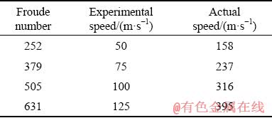
The airflow speeds used in experiments were calculated based on the same Froude number with the actual smelting bath, as given in Table 1.
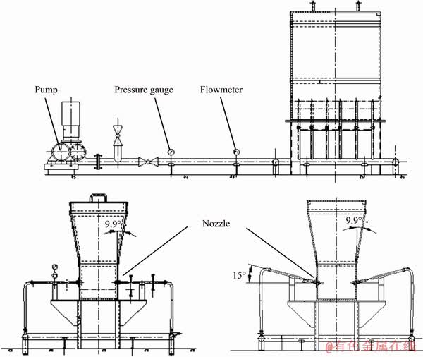
Fig. 1 Schematic diagram of experimental apparatus
Table 1 Airflow speeds in experiments and actual smelting bath based on same Fr
2.3 Experimental results and analysis
2.3.1 Influence of airflow speed
Figure 2 shows the pictures of the gas and liquid flow in the bath, in which the air is blown at different velocities from the nozzles submerged at 150 mm beneath the free surface. As shown in the pictures, when the airflow is blown at a relatively low speed, for instance, 50 m/s, large bubbles generate intermittently near the nozzles and the side walls. These large bubbles then gradually break into small ones when rising to the surface. When the airflow increases to 75 m/s, continuous bubble flow forms in the water, and violent fluctuation is observed in the free surface. With the speed further increasing to 100 m/s, two jet flow can be seen clearly in the bath (container). As the two jets impinge to the center of the bath, vigorous movement of the bubbles and water is caused above the nozzle, but the black indicator particles at the bottom are not stirred so strongly, of which only a few are carried by the water and suspended in the container. However, when the air speed increases to 125 m/s, the two air jets penetrate and meet at the center of the bath, bringing lots of indicator particles from the bottom which then float with the liquid.
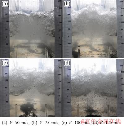
Fig. 2 Air blown from nozzles with submerged depth of 150 mm
Figures 3 and 4 respectively show how the penetration depth of the air jet and the fluctuation height of the free surface change with the airflow speed under conditions of three different submerged depths of the nozzles. Here, the penetration depth is defined as the maximum length that the airflow can reach along the nozzle axis, and the surface fluctuation height is defined as the height difference between the highest position of the surface level in the fluctuation and the stationary surface level. In order to avoid the accidental error in the data collecting, the average of multiple measurements is adopted. As illustrated in the plots, the penetration depth and the surface fluctuation height increase with the airflow speed, as the momentum of the airflow increases proportionally with the speed.
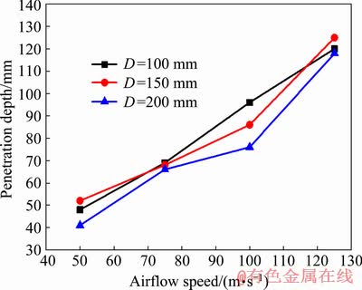
Fig. 3 Change of penetration depth of air jet with airflow speed
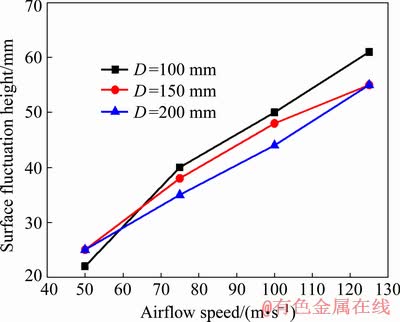
Fig. 4 Change of surface fluctuation height with airflow speed
2.3.2 Influence of penetration depth of airflow
Figures 5 and 6 respectively show how the penetration depth of the airflow and the surface fluctuation height change with the submerged depth of the nozzles under conditions of four different airflow speeds.
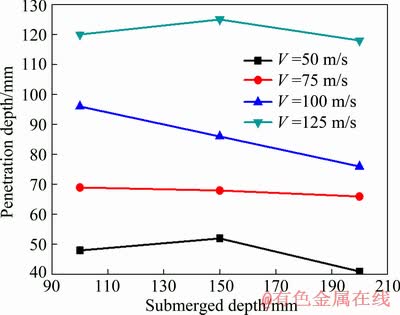
Fig. 5 Change of penetration depth with submerged depth of nozzles
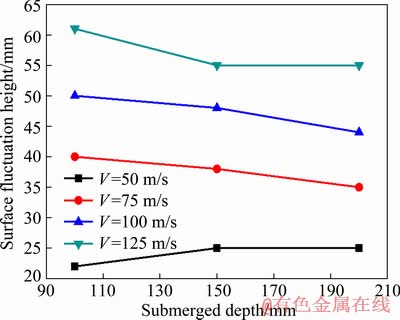
Fig. 6 Change of surface fluctuation height with submerged depth of nozzles
In general, the jet penetration depth and the surface fluctuation height decrease with the submerged depth of the nozzles, but the magnitudes of the changes are very limited. For example, when the submerged depth of the nozzle is doubled, the penetration depth of the air jet reduces by only 20.8%, and the fluctuation height of the surface changes by only 9.8%. These results indicate that the influence of the nozzle submerged depth on the agitation of water is not so significant when nozzles are submerged within a certain range of depth.
2.3.3 Influence of pointing angle of nozzles
Figure 7 shows the penetration depth and the surface fluctuation height changing with the airflow speed at different nozzle pointing angles. It can be clearly seen that the jet penetration depth and the surface fluctuation height are relatively small when the nozzle is of a downward angle of 15��. This is due to the decrease in the horizontal component of the velocity when the nozzle axis deviates from the horizontal direction. Therefore, adjusting the nozzles to a non-horizontal state will not help to improve the agitation of the water in the container. On the contrary, the jet penetration depth will decrease and the gas-liquid interaction in the bath will become weaker.
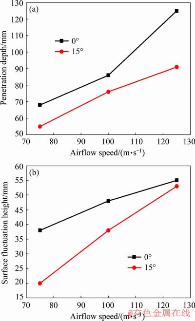
Fig. 7 Change of jet penetration depth (a) and surface fluctuation height (b) at different downward angles of nozzle
3 Numerical simulation
3.1 Computational domain and conditions
In order to investigate the details of the gas-liquid flow inside the bath, numerical simulation was also performed. As the fluid flow in the bath is typical turbulence, selecting a right turbulence model is very important for the numerical simulation. In most simulations, the k-e model is adopted to solve the turbulent flow. However, due to lots of bubbles and eddies existing in the water as observed in the experiment, this model was questioned whether it is suitable for the simulation in this study. As a result, three different turbulence models (the standard k-�� model, the realizable k-�� model and the SST k-�� model) were used for the simulation of the turbulent gas-liquid flow in the container, and the results were compared to the experiments to determine which model gives more reasonable results thus to be used in the future work.
To reduce the gird numbers, only one pair of nozzles was included in the computation domain, and the cross-sections of either side of the nozzles were defined as the periodic boundary so that the effects of other nozzles were considered. The hexahedron grids were adopted for the meshing of the domain. The schematics of the computational domain and the mesh are shown in Fig. 8.
Three cases with different turbulence models were computed respectively under the same boundary conditions. The submerged depth of the nozzles was 150 mm and the airflow speed was set to be 150 m/s in the computation. The boundary conditions defined in the computation are given in Table 2.
3.2 Numerical results and discussion
For the convenience of analysis, the cross- section where the axis of the nozzles lies is selected and named as Section C, to illustrate the simulation results (as shown in Fig. 9).
With the results of each case, the jet penetration depth and the surface fluctuation height in Section C are calculated and compared with the experiment. The relative errors and the sum of the squared relative error are given in Table 3. The relative errors of the penetration depth between the simulation and the experiment are all less than 5%, and the relative errors of the surface fluctuation height are less than 10%. Meanwhile, the sum of the squared relative error in Case 2 is the smallest, which indicates that the simulation result with the realizable k-�� model meets with the experiment the best for the prediction of the jet penetration depth and the surface fluctuation height. Hence, it is suggested that the realizable k-�� model is to be used as the turbulence model in the future simulation of the gas-liquid two phase flow in the side-blown bath.
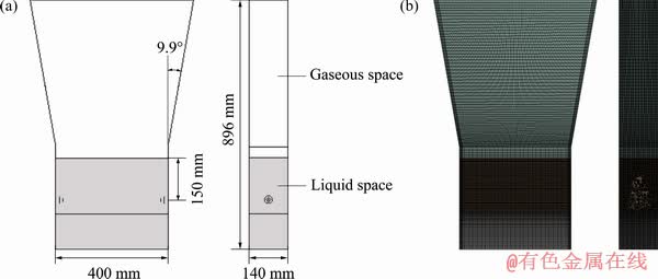
Fig. 8 Schematic of computational domain (a) and mesh (b) used in simulation
Table 2 Turbulence models and boundary conditions in numerical simulation
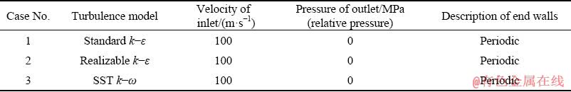
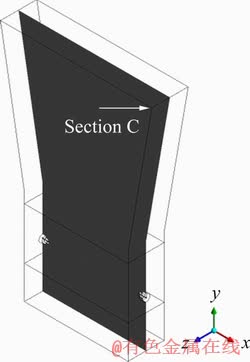
Fig. 9 Schematic diagram of Section C
The air volume fractions in Section C at the computational time of 1 s in three cases are shown in Fig. 10. It can be seen that in the results computed with the standard k-�� model and the realizable k-�� model, many small bubbles appear above the nozzle, and small bubbles break into smaller ones themselves. In the results with the SST k-�� model, the gas accumulates at the nozzle outlet, forming large bubbles and then detaching from the nozzle when it is large enough. Meanwhile, the bubbles in the upper part of water are relatively large and concentrated, which is different from the results observed in the experiment. Therefore, it seems that the standard k-�� models and the realizable k-�� model give a better description of the bubble scale in the side-blown bath.
Figure 11 illustrates the velocity contour and vectors of three cases at the time of 1 s. Relatively, in Case 2, the velocity in the central part of the water is rather small, which is a result of the less penetration depth of the gaseous phase. The velocity distribution in Case 3 is more concentrated, due to the fact that the largest bubble is generated in the liquid phase. Particularly, the area with the velocity close to zero is mainly distributed in the middle part of the two nozzles, which is marked with the red triangle in the Fig. 11. This means the gas flow in this area is weak, and it is hard to stir the liquid here at such a low velocity.
As shown in the diagram of the velocity vectors, the liquid flow above the nozzles is complicated. Two vortexes are formed near the side walls due to the movement of the bubbles, and it may be one of the factors that cause the erosion to both side walls. Moreover, as indicated by the vectors in the bottom part beneath the nozzles, a weak flow may exist there.
Table 3 Numerical values of penetration depth and fluctuation height
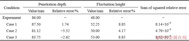
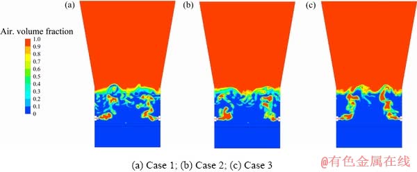
Fig. 10 Air volume fractions in Section C in three cases
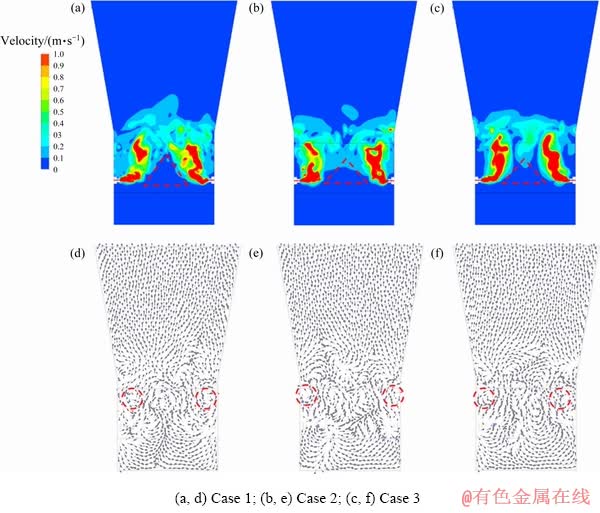
Fig. 11 Velocity contour (a-c) and vectors (d-f)
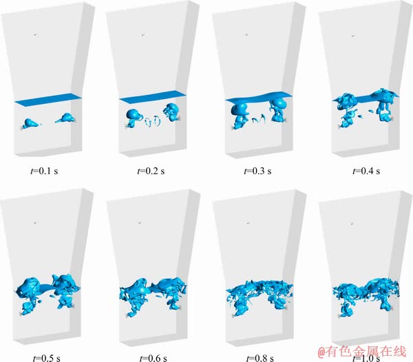
Fig. 12 Iso-surface of air volume fraction at different time in Case 2
Comparatively, the results with the realizable k-�� turbulence model meets better experiment data no matter in the jet penetration depth, the surface fluctuation height or the bubble size. So, the realizable k-�� turbulence model is recommended for future numerical simulation of the side-blown furnace.
For further investigation of Case 2, the iso-surfaces of air volume fraction equal to 0.5 at different time are shown in Fig. 12. The whole blowing process from the beginning can be divided mainly in three stages. The first one is the initial blowing stage, in which the airflow penetrates through water horizontally, and the time duration is about 0.1 s. The second stage is the bubble floating stage from 0.1 to 0.4 s, in which the initial large bubbles rise up to the free surface by the buoyancy until they break up. The last one is the stable stage after 0.5 s, in which lots of small bubbles are formed at the upper part of the nozzles because of the movement of the water. With the simulation results, the gas-liquid two-phase flow in the air-water system seems to reach a stable state after the air keeps blowing for about 0.5 s.
4 Conclusions
(1) In the hydraulic experiment, a bubble flow is obtained when the airflow velocity is at 50 m/s with a nozzle submerged depth of 150 mm. The bubbles are found large and discontinuously float from the nozzles. With the airflow velocity reaching 100 m/s, the jet flow is formed, and many small bubbles are continuously generated. When the airflow velocity is 125 m/s, the black indicator particles are stirred, floating in the water of the bath (container).
(2) The experimental results show that the airflow speed has a great influence on the liquid flow. The submerged depth of the nozzle has relatively smaller influence on the jet penetration depth and the surface fluctuation height of the water. When the nozzle is of a downward angle of 15��, the jet penetration depth and the surface fluctuation height both become decreased.
(3) The hydraulic experiment is numerically simulated using different turbulence models with Fluent. The result of the realizable k-�� turbulence model is closer to the experiment, in the results of the jet penetration depth, the fluctuation height of the free surface and the bubble scale. It is then concluded that the realizable k-�� model is more suitable to describe the turbulence flow in this study and is recommended to be used in future simulation of the gas-liquid two phase flow in the side-blown bath.
References
[1] ZHANG Zhen-yang, YAN Hong-jie, LIU Fang-kan, WANG Ji-min. Optimization analysis of lance structure parameters in oxygen enriched bottom-blown furnace [J]. The Chinese Journal of Nonferrous Metals, 2013, 23(5): 1471-1477. (in Chinese)
[2] YAN Hong-jie, LIU Fang-kan, ZHANG Zhen-yang, GAO Qiang, LIU Liu, CUI Zhi-xiang, SHEN Dian-bang. Influence of lance arrangement on bottom-blowing bath smelting process [J]. The Chinese Journal of Nonferrous Metals, 2012, 22(8): 2393-2400. (in Chinese)
[3] CUI Zhi-qiang, YAN Hong-jie, SHEN Dian-bang, YU Peng-fei. The research of metallurgical reaction engineering in oxygen bottom blowing copper smelting process [C]//5th International Symposium on High-Temperature Metallurgical Processing. The Minerals, Metals & Materials Society, 2014: 547-554.
[4] WEI J H, XIANG S H, FAN Y Y, YU N W, MA J C, YANG S L. Design and calculation of gas property parameters for constant area lance under conditions of friction flow with heating [J]. Ironmaking and Steelmaking, 2000, 27(4): 294-301.
[5] WEI J H, MA J C, FAN Y Y, YU N, YANG S L, XIANG S H, ZHU D P. Water modelling study of fluid flow and mixing characteristics in bath during AOD process [J]. Ironmaking and Steelmaking, 1999, 26(5): 363-371.
[6] BJURSTROM M, TILLIANDER A, IGUCHI M, JONSSON P. Physical-modeling study of fluid flow and gas penetration in a side-blown AOD converter [J]. ISIJ International, 2006, 46(4): 523-529.
[7] ZHOU Ping, CHENG Wei, MA Ji, XIA Zhong-wei, MA Ji. Experimental study on side-blown flowing characteristics [J]. Journal of Central South University (Science and Technology), 2016, 47(8): 2879-2883. (in Chinese)
[8] LIU Fan-han, LI Peng, WANG Hua, XU Jian-xin. Research on the behavior of side-blown gas jet [J]. Industrial Heating, 2017, 46(2): 14-18. (in Chinese)
[9] LIU Fang-kan. Numerical simulation and optimization of multiphase flow in bottom blowing lead smelting furnace [D]. Changsha: School of Energy Science and Engineering, Central South University, 2013. (in Chinese)
[10] XIA Yao. Numerical simulation and optimization of multiphase flow in the reduction furnace of the liquid rich-lead slag [D]. Changsha: School of Energy Science and Engineering, Central South University, 2014. (in Chinese)
[11] ZHANG Zhen-yang, CHEN Zhuo, YAN Hong-jie, LIU Fang-kan, LIU Liu, CUI Zhi-xiang, SHEN Dian-bang. Numerical simulation of gas-liquid multiphase flows in oxygen enriched bottom-blown furnace [J]. The Chinese Journal of Nonferrous Metals, 2012, 22(6): 1826-1834. (in Chinese)
[12] LI Yong-qing, ZHANG Xiao-hui, ZHANG Jia-yuan, ZHOU Jie-min, YAN Hong-jie. Numerical simulation and optimization of pulverized coal injection with enriched oxygen into blast furnace [J]. Applied Thermal Engineering, 2014, 67(1-2): 72-79.
[13] CHIBWE D K, AKDOGAN G, TASKINEN P. Numerical investigation of combined top and lateral blowing in a Peirce-Smith converter [J]. Chemical Product and Process Modeling, 2013, 8(2): 119-127.
[14] ZHANG H L, ZHOU C Q, BING W U, CHEN Y M. Numerical simulation of multiphase flow in a Vanyukov furnace [J]. Journal of the Southern African Institute of Mining & Metallurgy, 2015, 115(5): 457-463.
[15] ALMARAZ A, LOPEZ C, ARELLANO I, BARRON M A, JARAMILLO D, REYES F, PLASCENCIA G. CFD modelling of fluid flow in a Peirce�CSmith converter with more than one injection point [J]. Minerals Engineering, 2014, 56: 102-108.
[16] TANG Kai-le. Comprehensive study of flow and chemical reactions in a submerged lance copper smelting furnace [D]. USA: Purdue University, 2018.
[17] TASKINEN P, AKDOGAN G, KOJO I, LAHTINEN M, JOKILAAKSO A. Matte converting in copper smelting [J]. Mineral Processing and Extractive Metallurgy, 2019, 128(1-2): 58-73.
[18] ALAM M, IRONS G, BROOKS G, FONTANA A, NASER J. Inclined jetting and splashing in electric arc furnace steelmaking [J]. ISIJ International, 2011, 51(9): 1439-1447.
[19] HUDA N, NASER J, BROOKS G A, REUTER M A, MATUSEWICZ R W. Computational fluid dynamics (CFD) Investigation of submerged combustion behavior in a tuyere blown slag-fuming furnace [J]. Metallurgical and Materials Transactions B, 2012, 43(5): 1054-1068.
�����വ����¯������������ʵ�����ֵģ��
����ͥ1,2��������1���� 3��ף����3���� ��2���� ��3
1. ���ϴ�ѧ ұ���뻷��ѧԺ����ɳ 410083��
2. ��ɳ��ɫұ������о�Ժ����ɳ 410001��
3. ���ϴ�ѧ ��Դ��ѧ�빤��ѧԺ����ɳ 410083
ժ Ҫ����ij�����വ¯Ϊԭ�ͣ���������ԭ��������ˮģ�ͣ���������ǹ���������١���ǹ��û����Լ���ǹ��б�Ƕȶ���Һ����������Ӱ�졣ͬʱ�����ò�ͬ����ģ�Ϳ�չ��ˮģ�͵���ֵģ�⣬ͨ����ʵ��Ա�Ѱ������ʵ�����ģ�͡�ʵ���������������ٶȶ�Һ���ڲ��������Ӱ��ϴ���ǹ��û��ȶ�������Һ���ڲ��Ĺᴩ����Լ�Һ�沨���߶�Ӱ����Խ�С��ͬʱ������ǹ�������Ϊ15�� ʱ��������Һ���ڲ��Ĺᴩ����Լ�Һ�沨���߶Ⱦ�������С������ֵģ�������Է��֣�ʹ��realizable k-������ģ�����÷�����������ᴩ��ȡ�Һ�沨�������Լ�������״����ʵ����Ϊ�ӽ���
�ؼ��ʣ��വ¯��ˮģʵ�飻��ֵģ�⣻����ģ��
(Edited by Bing YANG)
Foundation item: Project (2018YFC1901606) supported by the National Key R&D Program of China
Corresponding author: Zhuo CHEN; Tel: +86-13974891750; E-mail: chenzhuo@csu.edu.cn
DOI: 10.1016/S1003-6326(19)65196-4
Abstract: Taking an oxygen enriched side-blown furnace as the prototype, a hydraulic model was established according to the similarity principle. The influence of three factors on the gas-liquid two-phase flow was analyzed, i.e. the airflow speed, the submerged depth and the downward angle of the nozzle. A numerical simulation of the hydraulic model was carried out trying to find the suitable turbulence model which can describe the side-blown two-phase flow correctly by comparing the simulation results with the experimental data. The experiment shows that the airflow speed has a great influence on the flow of the water. The submerged depth of the nozzle has a relatively smaller influence on the penetration depth and the surface fluctuation height in the liquid phase. When the nozzle is at a downward angle of 15��, the penetration depth and the surface fluctuation height are reduced. It is concluded that the numerical results with the realizable k-�� turbulence model are the closest to the experiment for the penetration depth, the surface fluctuation height and the bubble scale.
