
Trans. Nonferrous Met. Soc. China 25(2015) 863-872
Preparation of in-situ Cu/NbC nanocomposite and its functionally graded behavior for electrical contact applications
S. GHOLAMI SHIRI1,2, P. ABACHI1, K. POURAZARANG1, M. MOHAMMADI RAHVARD3
1. Department of Materials Science and Engineering, Sharif University of Technology, Tehran 11365-9466, Iran;
2. Damavand Petrochemical Company, Phase 2, Pars Special Economic Energy Zone, Boshehr 1993834557, Iran;
3. School of Materials Science and Engineering and Center of Excellence for High Strength Alloys Technology, Iran University of Science and Technology, Tehran 16846-13114, Iran
Received 8 March 2014; accepted 2 September 2014
Abstract:
Cu-15%NbC (volume fraction) powder was synthesized using the starting powders of Cu, Nb and graphite in a high energy vibratory disc mill for 7 h of milling under argon atmosphere. A composite sample and a Cu/NbC functionally graded material (FGM) sample were produced by using the two-step press and sintering at 900 ��C for 1 h under vacuum. The microstructure and physical and mechanical properties of the specimens were investigated. The field emission scanning electron microscopy, energy dispersive X-ray and X-ray diffraction analysis confirmed the synthesis of the nanostructure matrix of 18-27 nm with the nanoparticles reinforcement of 42 nm after sintering, verifying the thermal stability of this composite at high temperature. The hardness of Cu-15%NbC was five times greater than that of the pure Cu specimen. The volume reduction of the sample after the wear test decreased in comparison with the pure Cu specimen. The electrical conductivity of the composite specimen decreased to 36.68% IACS. The FGM specimen exhibited high electrical conductivity corresponding to 75.83% IACS with the same hardness and wear properties as those of the composite sample on the composite surface. Thus, Cu/NbC FGM with good mechanical and electrical properties can be a good candidate for electrical contact applications.
Key words:
Cu/NbC nanocomposite; in-situ composite; mechanical alloying; electrical contact; wear behavior;
1 Introduction
Copper is the best commercial metal for electrical and thermal applications [1,2]. The fact that copper is regarded as a criterion for the electrical conductivity measurements in the IACS standard shows its capability for electrical conductivity [3]. For applications such as electrical contacts, high performance switches, and spot welding electrodes, mechanical properties and thermal stability at elevated temperature, as well as electrical and thermal conductivity are required [4,5]. The alloying of copper with soluble materials enhances the mechanical properties, but these alloys contribute to an intense decrease in electrical conductivity [6]. Traditional high- strength copper alloys rely on precipitation hardening to increase their strength for low and intermediate temperature application but not at high temperatures [1]. Recently, the strengthening of copper with oxide and carbide reinforcement such as TiC [4], SiC [7,8], Al2O3 [9,10], Cu2O [6], and NbC [11] has attracted attention of many researchers. It has been reported that the reinforcing of copper with NbC makes its mechanical and electrical properties more proper in comparison with other reinforcements [2,11,12]. The fine reinforcement particles with homogeneous distribution in the matrix enhance the mechanical properties and thermal stability of the composite. These fine particles can be produced by in-situ formation during mechanical alloying.
Many engineering components require contradictory material properties, such as lightweight, high wear resistance, electrical conductivity, hardness and toughness. Functionally gradient materials (FGMs) fill the gap in materials science that the components require different properties in different positions and the optimal property is not achievable with the homogeneous cross-section materials. FGMs are materials with variation of composition and microstructure along their thickness [13,14]. For electrical contacts, the hardness, wear resistance and thermal stability of the surface, as well as the electrical conductivity of bulk are required [5]. FGMs are composite materials with properties and microstructure continuously changing along a specific material direction. The main advantages of functionally graded structures are the possibility of taking advantages of each base material��s properties simultaneously [15]. Studies on functionally graded copper structures have been limited to few structures such as Cu/Ni [15], Cu/W [16,17], Cu/Al [18] and Cu/SiC [19]. In these studies, mostly, the microstructure of the specimens has been investigated, but their mechanical properties such as wear resistance and hardness, as well as their physical properties, including electrical conductivities have not been considered. To provide a copper-based specimen with good electrical conductivity and mechanical properties, further investigation on copper/reinforcement graded structure is needed. In this study, the microstructure, electrical conductivity, hardness and wear resistivity of the Cu/NbC nanocomposite and the composite with the gradient of NbC reinforcement in the copper matrix were investigated.
2 Experimental
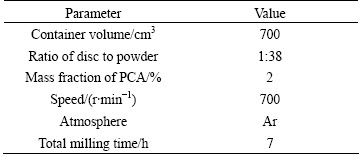
In this study, the Cu-15%NbC (volume fraction) powder composite was synthesized by milling a mixture of the Cu powders (99.5% purity, 0.045 mm, produced by Merck Company), Nb (99.8% purity, 0.045 mm, produced by Alfa Aesar Company) and graphite (99.99% purity, the average particles size <180 ��m, produced by Merck Company) in a high energy vibratory disc mill under argon. Stearic acid was used as the process control agent (PCA) in order to prevent excessive cold welding of these powders during ball milling. The milling parameters are shown in Table 1.
Table 1 Milling parameters of vibratory disc mill
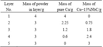
To obtain fine distribution reinforcements in Cu matrix, firstly, Cu and 12.7% Nb (volume fraction) and PCA were milled for 5 h to achieve the super-saturated solid solution of Nb in Cu. After that the stoichiometric amount of graphite was added to the mixture and the milling was continued for 2 h afterward. A pure copper was also milled for 7 h as a witness sample. The as-milled powders during milling were extracted after 1, 2, 3, 5 and 7 h of milling time for examination by the X-ray diffraction (XRD) analysis and scanning electron microscopy (SEM). The crystallite size and internal strain were determined by the Williamson-Hall method [20]. The average values of the internal strain and crystallite size of Cu and NbC were calculated from the first three peaks (111), (200) and (220) for both the Cu and NbC. For preparation of the FG specimen, pure Cu and Cu-15%NbC powders were used. The FGM specimen, as shown in Fig. 1, consisted of five layers (approximately 1 mm each), varying in composition of the NbC particles along the thickness. Table 2 shows the amount of each base powder used in layers.

Fig. 1 Composition of each layer for FGM specimens
Table 2 Composition of each layer in FGM specimen
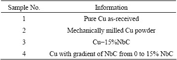
For the compaction of each type of the powders to a pellet with the radius of 25 mm and thickness of 5 mm, the cold and warm presses were performed subsequently. At first, a 50 MPa pre-compaction axial load was applied to the powder and the powder was subjected to 185 MPa pressure after heating this compact at 450 ��C for 20 min. Heating causes the stearic acid (PCA) removal and softening of the milled powder. The compacts were sintered at 900 ��C for 1 h under 0.133 Pa vacuum. To confirm the formation of the phases in the sintered specimen, the XRD test was performed. To study the microstructure, the field emission scanning electron microscopy (FE-SEM) and energy dispersive X-ray (EDX) analysis were used. Archimedes immersion method densitometry was utilized to determine the density of the specimen according to ASTM B328-96. The hardness was measured by the Vickers microhardness tester at an applied load of 10 N for 25 s. The electrical specific resistivity of samples was recorded by a four-point probe set-up. The wear behavior of the specimens was investigated by a pin on the disc apparatus under the constant wear distance of 1000 m, load of 20 N and sliding velocity of 0.25 mm/s. The information of samples is given in Table 3.
Table 3 Information of samples
3 Results and discussion
3.1 Microstructure evolution
Figure 2 illustrates the evolution of powder morphology from the flake shape to the spherical one at different milling time. At the early stage of milling, copper powders are ductile. Powder particles are subjected to high energy collision which causes intense plastic deformation, and the morphology of the powder changes to flake shape. Increasing the milling time leads to increasing the density of defects such as dislocations and stacking faults followed by fracture and cold welding between particles. Then, the powder becomes brittle by fracturing the corner of brittle powder, and the morphology changes to elliptical and then spherical shape [1].
Figure 3 shows the XRD patterns of Cu-15%NbC at different milling time. The changes in XRD patterns at different milling time confirm the change of the microstructure of the powders. By increasing the milling time, the XRD pattern of the powder shows the remarkable line broadening of Cu and Nb and the intensity reduction of Nb peaks. After 5 h of milling, Nb peaks can hardly be detected. This confirms that Nb is completely dissolved within the copper lattice during milling. After 5 h of milling, the graphite powder is added to the mixture of the milled powder. The C peak can be seen in this pattern. The broad and weak peaks of NbC appear after 7 h of milling. ZUHAILAWATI et al [1,2,21] reported that the synthesis of NbC occurs only after heat treatment because the amount of energy transferring to the powder was not sufficiently high to overcome the activation energy required for the reaction to take place even in the long time of milling up to 54 h. However, MARQUES et al [5,22] and ZUHAILAWATI et al [23] reported that the partial formation of NbC occurs during milling and the NbC formation is completed after heat treatment.
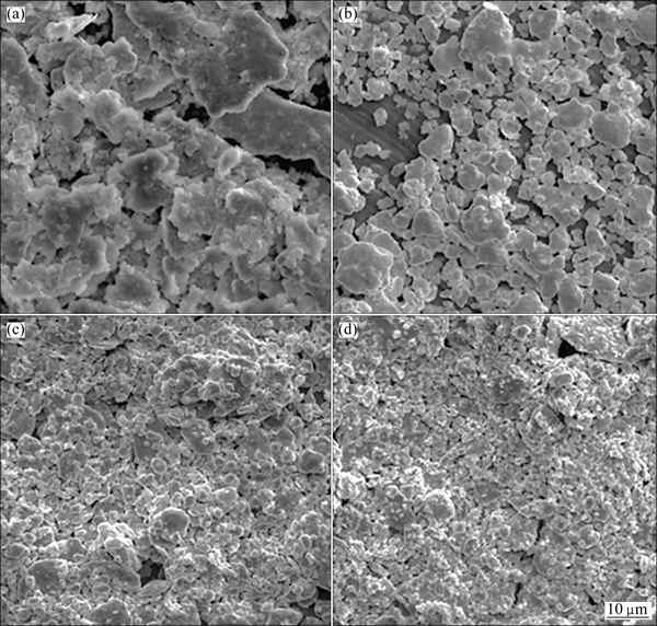
Fig. 2 Powder morphologies at milling time of 20 min (a), 2 h (b), 5 h (c) and 7 h (d)
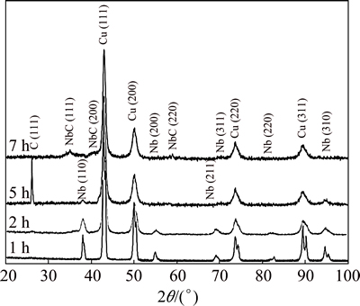
Fig. 3 XRD patterns of Cu-15%NbC powders at different milling time
The lattice parameter of Cu was determined by the Nelson-Riley method [24]. Figure 4 shows lattice parameters of Cu at different milling time. At the early stage of milling, the increase of the milling time causes an increase in the lattice parameter. The lattice parameter reaches to the maximum of 3.642  after 5 h of milling and then reduces to 3.639 after 7 h of milling. The atomic radii of Cu and Nb are 1.28 and 1.45 , respectively. The dissolving of Nb in the interstitial place of the Cu lattice results in the expansion of the lattice parameter. Increasing the amount of solvent Nb atoms followed by the increase of the milling time leads to the further expansion of the lattice and the increase of the Cu lattice parameter. The decrease of the lattice parameter after 5 h of milling may be due to Fe contamination which enters powder mixture from the collisions of the disc and wall which are all Fe-based. There is no trace of Fe in XRD pattern, indicating that Fe has been dissolved in Cu lattice. Due to the smaller atomic radius of Fe (1.27 ) than those of Cu and Nb, the interstitial acceptance of Fe in Cu lattice decreases the lattice parameter. Figure 5(a) shows the cross-section of the as-milled powder which is selected for the mapping analysis to trace the alloying elements. Figures 5(b) and (c) show the mapping of Cu and Nb elements, respectively. Fine distribution of the Nb atoms can be seen in Fig. 5(b), which demonstrates the good alloying of the Nb atoms in the matrix. Figure 5(d) shows Fe mapping from the cross-section of the as-milled powder, confirming the presence of Fe atoms in powders. The precipitations of Nb and the formation of NbC after adding graphite to powder are other possible reasons for decreasing the lattice parameter. Also, the addition of graphite to the powder may decrease the lattice parameter of Cu. BOTCHAROVA et al [25] declared that after supersaturate solution of the interstitial atoms in the lattice, these atoms occupy the interstitial site of the lattice by entering more atoms into the lattice.

Fig. 4 Lattice parameter of Cu at different milling time
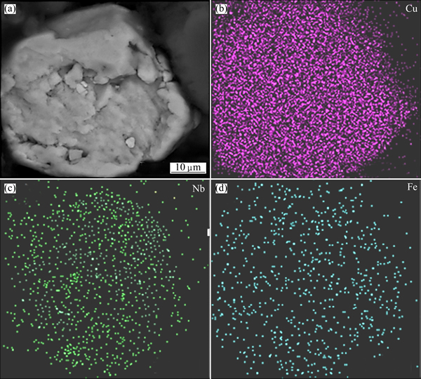
Fig. 5 Cross-section of as-milled powder (a) and mapping analysis of Cu (b), Nb (c) and Fe (d)
The crystallite size and lattice strain were measured by the Williamson-Hall method. Figure 6 illustrates the variation of lattice strain and crystallite size of the specimen at different milling time. The crystallite size of Cu decreases from 61 nm to 20 nm and the lattice strain increases from 0.02% to 0.16% after 7 h of milling. The crystallite size of Nb corresponds to 18 nm after 7 h of milling.
For specimen preparation, the powders were subjected to two-step pressing. Figure 7 shows the cross-section of Sample 4 after sintering. No macro-crack is observed in the specimens using visual testing, and different layers of Sample 4 can clearly be seen in Fig. 7.
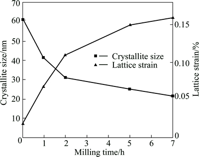
Fig. 6 Crystallite size and lattice parameter of specimen at different milling time
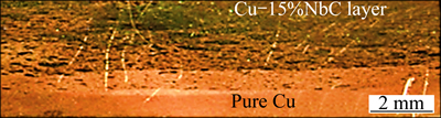
Fig. 7 Macro image of cross-section of Sample 4
Figure 8 shows the optical microstructures of the specimens. It can be seen that the porosity of the specimen increases in Samples 2 and 3 in comparison with that of pure Cu. The mechanical milling (MM) process increases dislocation density and the stacking faults in the powders and the presence of the Nb atoms in the Cu lattice and the formation of NbC decrease the formability and compatibility of the powders [4]. Hence, the compaction of the mechanical milling powder and the composite powder is more difficult than that of pure metal, thereby increasing the porosity and decreasing the density of the specimens.
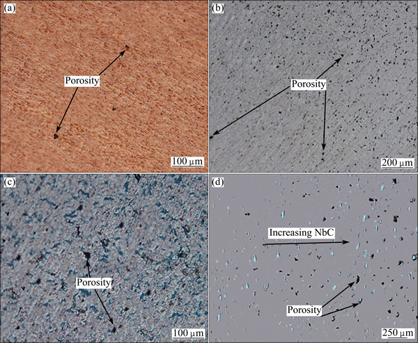
Fig. 8 Optical micrographs of Sample 1 (a), Sample 2 (b), Sample 3 (c) and Sample 4 (d)
Figure 9 shows the XRD pattern of the sintered composite after 7 h of milling and heat treatment at 900 ��C. The diffraction peaks from the in-situ composite are stronger and narrower than those of the as-milled powder. It can be seen that there is no trace of Nb and graphite. The peaks for NbC become sharper and stronger after heat treatment, confirming the complete synthesis of NbC after sintering. The severe plastic deformation during mechanical alloying and enormous energy stored in the powder facilitate the formation of NbC during sintering [2]. Without the hard working caused by mechanical milling, the direct formation of NbC just occurs at high temperatures higher than 1500 ��C [2]. By using the Nelson-Riley and Williamson-Hall equations for Cu peaks, the lattice parameter, lattice strain and crystallite size are obtained to be 3.616 nm, 0.03% and 41 nm, respectively, after sintering.
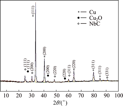
Fig. 9 XRD pattern of Cu-15%NbC after 7 h of milling and heat treatment at 900 ��C
Figure 10 shows the SEM image of the whole cross-section of Sample 4 with Cu and Nb mapping after sintering. The gradient of Nb atoms well distributed without clustering can be seen in Fig. 10(c). Porosity increases with increasing amount of the reinforcement (Fig. 10(a)). The increase of porosity by increasing the reinforcement occurs along the section.
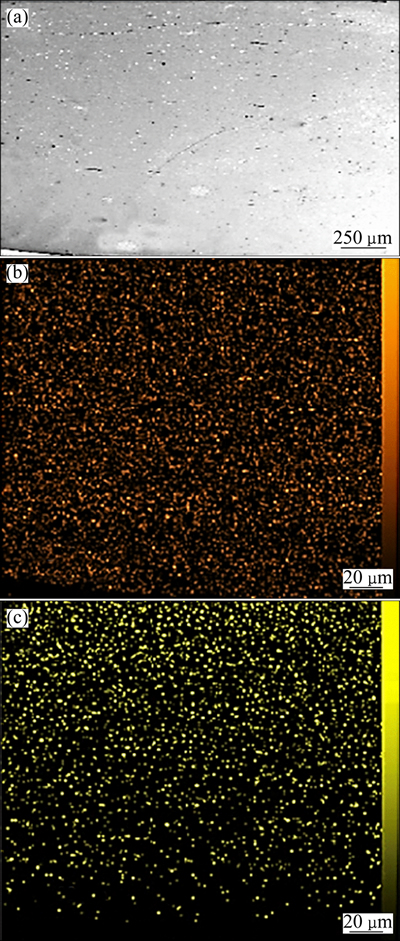
Fig. 10 SEM image of Sample 4 (a) and mapping of Cu (b) and Nb (c)
Figure 11 shows the field emission scanning electron microscopy (FE-SEM) images of Samples 2 and 3 after sintering. It can be seen that the average crystallite size of the composite is about 38 nm in Fig. 11(b). This picture confirms the result of crystal measurement by using XRD peaks and the Williamson- Hall equation. Figure 11(a) obviously shows the growth of crystallite during sintering. The crystallite size of mechanically alloyed Cu increases to micrometric size after sintering. The comparison of Figs. 11(a) and (b) demonstrates the thermal stability of Sample 3 after 1 h sintering at high temperatures. The precipitation of the NbC nanoparticle is the main reason for the remaining of the nanoscale Cu. NbC particles act as an obstacle and prevent the crystallite growth after sintering.
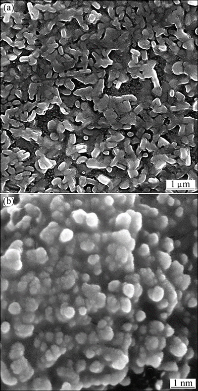
Fig. 11 FE-SEM images of Samples 2 (a) and 3 (b) after sintering at 900 ��C for 1 h
Figure 12(a) shows the back scatter image of Sample 3 after sintering. Because of higher atomic mass of NbC in comparison with Cu, the NbC particles appear brighter. This is also confirmed by the EDX analysis of these particles, which is illustrated in Fig. 12(b) showing high contents of Nb and C in this area. The average size of NbC particles is 36 nm and good distribution of NbC can be seen in this picture. XRD, FE-SEM and EDX results confirm the in-situ formation of the nano NbC particles in the nano-crystallite Cu matrix with fine distribution of reinforcement. The approximately constant crystallite size about 40 nm is a reason for the thermal stability of the Cu/NbC composite.
3.2 Mechanical and physical properties
Table 4 illustrates the mechanical and physical properties of different specimens after sintering. Sample 1 is the dense specimen in comparison with the other samples due to the formability of the pure Cu powder. The hard working on the Cu powder increased the lattice strain and dislocation density and decreased the crystallite size of the specimens [23]. Therefore, the compatibility of the MM powder is more difficult than the pure Cu, and the density of Sample 2 is lower than that of Sample 1. In Sample 3, in addition to the hard working on the powders, the presence of ceramic reinforcement causes lower density of the specimen. The presence of pure Cu in Sample 4 increased the formability of powder and allowed for the flow of materials into the porosities. Thus, the density of the FGM is higher than that of Sample 3. The low density in all samples is due to the low pressure applied during the compaction because of the lake of super alloy die which cannot bear high pressure.
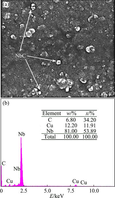
Fig. 12 FE-SEM back scatter (BS) image of Sample 3 after heat treatment (a) and EDX analysis from brighter particle (b)
As reported in Table 4, the hardness of Sample 3 increases abruptly in comparison with that of Samples 1 and 2. The increase in hardness of composite sample is mainly attributed to the increase in the NbC phase and the decrease in the movement of the dislocation according to the Orowans mechanism [4,23]. The fine dispersion of reinforcement as shown in Fig. 12 decreases the obstacle distance and increases the hardness of the composite. The effect of increasing hardness due to the decrease of the crystallite size and internal strain can be proven by comparing hardness of Samples 1 and 2. Figure 13 illustrates the hardness profile in the cross-section of Sample 4. The increase of hardness by increasing NbC particles can be seen in this plot.
Table 4 Mechanical and physical properties of different samples after sintering

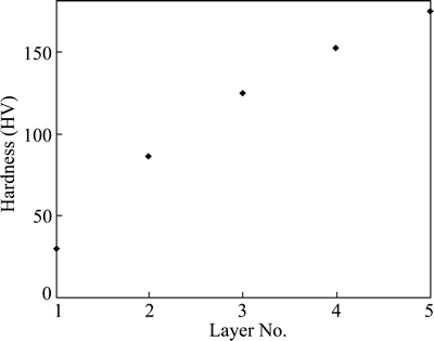
Fig. 13 Vickers hardness of different layers of Sample 4
According to Table 4, the volume reduction of the worn Sample 3 is lower than that of Samples 1 and 2. Usually, increasing hardness improves the wear behavior of the material. Sample 3 shows better wear behavior in comparison with the other samples. The wear behavior of the composite surface of Sample 4 can be considered the same as Sample 3. Figures 14(a) and (b) show the SE and BS SEM images from the sliding surface of pin of Sample 1, respectively, and Fig. 14(c) shows debris morphology after wear. The BS image and EDX analysis show the oxidation of the pin surface at a 1000 m distance of the wear process, which can be seen as a dark area in Fig. 14(b).
An increase in loading and the wear distance increases the sliding surface temperature, causing the softening and formability of the pin surface and the increase of the volume reduction of the specimen. The oxide layer on the pin surface and the oxide debris showed tribo-chemical mechanism during the wear test. The tribo-chemical wear is the characteristic of two- contact surface which has reaction with the surrounding environment. The wear process continues with the formation and dislodge of the product layers. The most common class of tribo-chemical wear mechanisms is oxidation which can be seen in BS SEM in Fig. 14 [26].
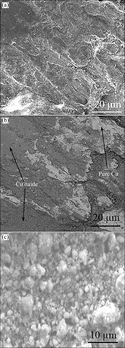
Fig. 14 SEM images of morphology of worn pin surface (a), BS imaging of worn pin surface (b) and morphology of debris (c) of Sample 1
Figure 15 shows the worn pin surface and debris morphology of Sample 3. The low-depth groves in Fig. 15 confirm high hardness and good wear behavior of the composite sample. The nucleation and propagation of the crack can be seen in Fig. 15(b). The presence of cracks on the worn surface and flake morphology of the debris, as can be seen in Fig. 15(c), confirms the delamination mechanism in the worn composite sample.
The composite surface of the FGM sample has the same wear behavior. The mass reduction of different samples shows the enhancement of wear resistivity in the composite sample in comparison with that of the other samples.
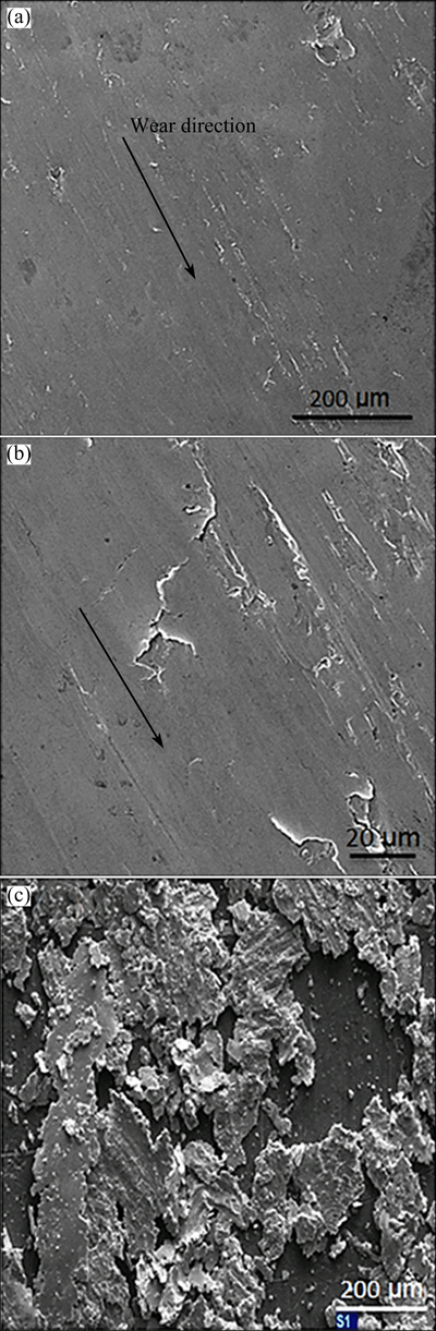
Fig. 15 Macrograph (a) and micrograph (b) of worn pin surface and powder morphology (c) of Sample 3
The electrical conductivity of different samples is also given in Table 4. The mechanically milled powder shows a decrease in electrical conductivity in comparison with Sample 1. The increase of the scattering areas such as porosities, boundaries and dislocations is the main reason for this decrease. The electrical conductivity of Sample 3 is very low. The presence of reinforcements in addition to the previous reason resulted in an abrupt increase in the scattering area and a decrease in the electrical conductivity of this sample. As reported in Table 4, the electrical conductivity of Sample 4 is high. The pure Cu layer and the Cu-rich layer of the FGM sample provide the electron movement path and result in high conductivity of this sample. The comparison of the electrical conductivity of Samples 3 and 4 shows the enhancement of conductivity in the FGM specimen.
4 Conclusions
1) NbC was formed partially after 7 h of milling with a high energy vibratory disc mill. The syntheses of the nanostructure Cu with nanoreinforcement of NbC was addressed by the FE-SEM, EDX and XRD analysis.
2) Constant crystallite size before and after sintering at 900 ��C conceded the thermal stability of the composite. The wear behavior and hardness of the composite sample show an outstanding improvement in comparison with those of pure copper because of the homogeneous and fine distribution of the NbC particles.
3) For electrical contact applications, the hardness and wear resistivity of the surface with electrical conductivity are required. The Cu/NbC functionally graded structure shows the advantage of both Cu and the composite sample. This sample shows high wear resistivity and hardness on the composite surface, while the electron movement path is provided through Cu-rich layers.
Acknowledgement
The authors want to express their gratitude to Sharif University of Technology for the financial support. And also the authors would like to thank Dr. S. AMIRI for valuable guidance.
References
[1] ZUHAILAWATI H, MAHANI Y.Effects of milling time on hardness and electrical conductivity of in situ Cu-NbC composite produced by mechanical alloying [J]. Journal of Alloys and Compounds, 2009, 476: 142-146.
[2] ZUHAILAWATI H, OTHMAN R, LONG B D, UMEMOTO M. Synthesis of copper�Cniobium carbide composite powder by in situ processing [J]. Journal of Alloys and Compounds, 2008, 464: 185-189.
[3] ASTM B193-02. Standard test method for resistivity of electrical conductor materials [S].
[4] LONG B D, OTHMAN R, UMEMOTO M, ZUHAILAWATI H. Spark plasma sintering of mechanically alloyed in situ copper�Cniobium carbide composite [J]. Journal of Alloys and Compounds, 2010, 505: 510-515.
[5] MARQUES M T, FERRARIA A M, CORREIA J B, BOTELHO REGO A M, VILAR R. XRD, XPS and SEM characterisation of Cu�CNbC nanocomposite produced by mechanical alloying [J]. Materials Chemistry and Physics, 2008, 109: 174-180.
[6] SHARMA I G, CHAKRABORTY S P, MAJUMDAR S, BIDAYE A C, SURI A K. A study on preparation of copper�Cniobium composite by aluminothermic reduction of mixed oxides [J]. Journal of Alloys and Compounds, 2002, 336: 247-252.
[7] CELEBI EFE G, ZEYTIN S, BINDAL C. The effect of SiC particle size on the properties of Cu�CSiC composites [J]. Materials and Design, 2012, 36: 633-639.
[8] CELEBI EFE G, IPEK M, ZEYTIN S, BINDAL C.An investigation of the effect of SiC particle size on Cu�CSiC composites [J]. Composite (Part B): Engineering, 2012, 43: 1813-1822.
[9] SHEHATA F, FATHY A, ABDELHAMEED M, MOUSTAFA S F. Fabrication of copper-alumina nanocomposites by mechano- chemical routes [J]. Journal of Alloys and Compounds, 2009, 476: 300-305.
[10] ZUHAILAWATI H, LEONG C K. Properties and spot welding behaviour of copper�Calumina composites through ball milling and mechanical alloying [J]. Materials and Design, 2008, 29: 1311-1315.
[11] MARQUES M T, LIVRAMENTO V, CORREIA J B. Production of copper�Cniobium carbide nanocomposite powders via mechanical alloying [J]. Materials Science and Engineering A, 2005, 399: 382-386.
[12] LONG B D, ZUHAILAWATI H, UMEMOTO M, TODAKA Y, OTHMAN R. Effect of ethanol on the formation and properties of a Cu-NbC composite [J]. Journal of Alloys and Compounds, 2010, 503: 228-232.
[13] MORTENSEN A, SURESH S. Functionally graded metals and metal�Cceramic composites: Part 1. Processing [J]. International Materials Review, 1995, 40(6): 239-265.
[14] MOHAMMADI RAHVARD M, TAMIZIFAR M, BOUTORABI S M A, GHOLAMI SHIRI S. Effect of superheat and solidified layer on achieving good metallic bond between A390/A356 alloys fabricated by the new melt process (cast-decant-cast) [J]. Transaction of Nonferrous Metals Society of China, 2014, 24: 665-672.
[15] RUBIO W M, PAULINO G H, SILVA E C N. Analysis, manufacture and characterization of Ni/Cu functionally graded structures [J]. Materials and Design, 2012, 41: 255-265.
[16] PINTSUK G, BRU NINGS S E, LINKE J, SMID I. Development of W/Cu functionally graded materials [J]. Fusion Engineering and Design, 2003, 66-68: 237-240.
[17] LIU R, HAO T, WANG K, ZHANG T, WANG X P, LIU C S, FANG Q F. Microwave sintering of W/Cu functionally graded materials [J]. Journal of Nuclear Materials, 2012, 431: 206-211.
[18] TU R, SHEN Q, HUA J S, ZHANG L M, YUAN R Z. Fabrication of Al-Cu system with functionally graded density profiles [J]. Functionally Graded Materials, 1996, 1997: 307-311.
[19] LING Yun-han, LI Jiang-tao, GE Chang-chun. Fabrication and evaluation of SiC/Cu functionally graded material used for plasma facing components in a fusion reactor [J]. Journal of Nuclear Materials, 2002, 303: 188-195.
[20] KUSCHKE W M, KELLER R M, GRAHLE P, MASON R, ARZT E. Mechanisms of powder milling investigated by X-ray diffraction and quantitative metallography [J]. Z Metallkde, 1995, 86(12): 804-813.
[21] ZUHAILAWATI H, YONG T L. Consolidation of dispersion strengthened copper�Cniobium carbide composite prepared by in situ and ex situ methods [J]. Materials Science and Engineering A, 2009, 505: 27-30.
[22] MARQUES M T, LIVRAMENTO V, CORREIA J B, ALMEIDA A, VILAR R. Study of early stages of Cu�CNbC nanocomposite synthesis [J]. Journal of Alloys and Compounds, 2007, 434: 481-484.
[23] ZUHAILAWATI H, SALIHIN H M, MAHANI Y. Microstructure and properties of copper composite containing in situ NbC reinforcement: Effects of milling speed [J]. Journal of Alloys and Compounds, 2010, 489: 369-374.
[24] CULLITY B D. Elements of X-ray diffraction [M]. Reading: Addison Wesley, 1967: 259.
[25] BOTCHAROVA E, HEILMAIER M, FREUDENBERGER J, DREW G, KUDASHOW D, MARTIN U. Supersaturated solid solution of niobium in copper by mechanical alloying [J]. Journal of Alloys and Compounds, 2003, 351: 119-125.
[26] FUSHCHICH O I, DANYLUK S, KOVALCHENKO A M. The tribological properties and mechanism of wear of Cu-based sintered powder materials containing molybdenum disulfide and molybdenumdiselenite under unlubricated sliding against copper [J]. Wear, 2012, 106: 290-291.
Cu/NbC�����ϲ��ϵ�ԭλ�ϳɼ����ڵ紥ͷ����Ӧ���еĹ����ݶ���Ϊ
S. GHOLAMI SHIRI1,2, P. ABACHI1, K. POURAZARANG1, M. MOHAMMADI RAHVARD3
1. Department of Materials Science and Engineering, Sharif University of Technology, Tehran 11365-9466, Iran;
2. Damavand Petrochemical Company, Phase 2, Pars Special Economic Energy Zone, Boshehr 1993834557, Iran;
3. School of Materials Science and Engineering and Center of Excellence for High Strength Alloys Technology,
Iran University of Science and Technology, Tehran 16846-13114, Iran
ժ Ҫ��ԭ��Cu��Nb��ʯī��ĩ���ڸ�������ʽ��ĥ�ǣ��������������ĥ7 h�Ʊ�Cu-5%NbC(�������)��ĩ����������ѹ�Ʒ��������900 ��C�ս�1 h�������Ƶ�Cu-NbC�����ݶȲ��Ϻ��ϲ�����Ʒ���о���Ʒ������֯���������ܺ���ѧ���ܡ�������ɨ��羵������ɫɢX���ߺ�X������������������Ʒ���սᴦ�������ߴ�Ϊ18~27 nm�����ṹ�����к��д�СΪ42 nm����������ǿ�֤࣬ʵ�����Ƹ��ϲ��ϵĸ������ȶ��ԡ�Cu-15%NbC���ϲ�����Ʒ��Ӳ���Ǵ�Cu��ƷӲ�ȵ�5��������ڴ�Cu��Ʒ��ĥ���Cu-15%NbC���ϲ�����Ʒ�����ĥ������С���ҵ絼�ʽ�����36.68%IACS������ڸ��ϱ����еĸ��ϲ�����Ʒ��Cu/NbC�����ݶȲ�����Ʒ�ھ����븴�ϲ�����ͬ��Ӳ�Ⱥ�ĥ�����ܵ������£���ʾ��75.83% IACS�Ľϸߵ絼�ʡ���ˣ�����������ѧ���ܺ͵�ѧ���ܵ�Cu/NbC�����ݶȲ��Ͻ���Ϊ�ܺõĵ紥ͷ���ϡ�
�ؼ��ʣ�Cu/NbC�����ϲ��ϣ�ԭλ���ϲ��ϣ���е�Ͻ��紥ͷ��ĥ������
(Edited by Wei-ping CHEN)
Corresponding author: M. MOHAMMADI RAHVARD; Tel: +98-9151806075; Fax: +98-2177240480; E-mail: M.Rahvard@yahoo.com
DOI: 10.1016/S1003-6326(15)63675-5
Abstract: Cu-15%NbC (volume fraction) powder was synthesized using the starting powders of Cu, Nb and graphite in a high energy vibratory disc mill for 7 h of milling under argon atmosphere. A composite sample and a Cu/NbC functionally graded material (FGM) sample were produced by using the two-step press and sintering at 900 ��C for 1 h under vacuum. The microstructure and physical and mechanical properties of the specimens were investigated. The field emission scanning electron microscopy, energy dispersive X-ray and X-ray diffraction analysis confirmed the synthesis of the nanostructure matrix of 18-27 nm with the nanoparticles reinforcement of 42 nm after sintering, verifying the thermal stability of this composite at high temperature. The hardness of Cu-15%NbC was five times greater than that of the pure Cu specimen. The volume reduction of the sample after the wear test decreased in comparison with the pure Cu specimen. The electrical conductivity of the composite specimen decreased to 36.68% IACS. The FGM specimen exhibited high electrical conductivity corresponding to 75.83% IACS with the same hardness and wear properties as those of the composite sample on the composite surface. Thus, Cu/NbC FGM with good mechanical and electrical properties can be a good candidate for electrical contact applications.
