
Influence of alloy components on arc erosion morphology of Ag/MeO electrical contact materials
Chun-ping WU1,2,3, Dan-qing YI2, Wei WENG3, Su-hua LI3, Jie-min ZHOU1
1. School of Energy Science and Engineering, Central South University, Changsha 410083, China;
2. Key Laboratory for Nonferrous Metal Materials, Ministry of Education,
School of Materials Science and Engineering, Central South University, Changsha 410083, China;
3. FuDa Alloy Materials Co., Ltd., Wenzhou 325025, China
Received 7 February 2015; accepted 25 August 2015
Abstract:
Arc erosion morphologies of Ag/MeO(10) electrical contact materials after 50000 operations under direct current of 19 V and 20 A and resistive load conditions were investigated using scanning electron microscope (SEM) and a 3D optical profiler (3DOP). The results indicated that 3DOP could supply clearer and more detailed arc erosion morphology information. Arc erosion resistance of Ag/SnO2(10) electrical contact material was the best and that of Ag/CuO(10) was the worst. Arc erosion morphology of Ag/MeO(10) electrical contact materials mainly included three different types. Arc erosion morphologies of Ag/ZnO(10) and Ag/SnO2(10) electrical contact materials were mainly liquid splash and evaporation, and those of Ag/CuO(10) and Ag/CdO(10) were mainly material transfer from anode to cathode. Arc erosion morphology of Ag/SnO2(6)In2O3(4) electrical contact materials included both liquid splash, evaporation and material transfer. In addition, the formation process and mechanism on arc erosion morphology of Ag/MeO(10) electrical contact materials were discussed.
Key words:
Ag/MeO electrical contact material; alloy component; arc erosion morphology; three-dimensional optical profiler;
1 Introduction
Ag/MeO electrical contact materials have been widely used in switching devices because of their excellent properties in minimizing contact welding and arc erosion during operation [1]. Because contact failure has caused serious accident, the reliability of contact was one of the most important factors. The interaction between the arc and the contact pair was a complex phenomenon involving several mechanisms of material erosion and deposition [2]. Arc erosion had many influencing factors, such as electrical factors [3-5], mechanical factors [6,7], material factors [8,9] and environmental factors [10]. Arcing can produce changes in contact surface morphology and composition [11]. Surface morphology changes also caused changes in contact resistance, which generally increased with repeated arcing [12]. So, it was desirable to clearly understand the relationship between surface morphology and arc erosion. It was the key to obtain the useful and detailed information on contact surface morphology for clearly understanding the relationship between arc erosion and morphology. Conventionally, mass change of electrodes was measured for indirectly evaluating changes in the contact surface configuration caused by operation of the contact. Although this was still a useful technique, sufficient mass change may not exist to enable accurate measurement in some cases. In addition, mass change was not likely to provide sufficient information regarding contact surface configuration, because it can not describe the contact profile. For example, when both a peak and a crater were formed on the same electrode, mass gain associated with the peak and mass loss associated with the crater might cancel each other, resulting in only a slight total mass change. Furthermore, traditional two-dimensional morphology detection method (SEM) has been used to give good qualitative results [13], but it was difficult to truly characterize the arc erosion surface profile of electrical contact materials.
Thus, it was desirable to directly obtain information on contact surface profiles. Some techniques currently available for evaluating contact surface configuration mainly are scanning tunneling microscopy (STM), atomic force microscopy (AFM), scanning laser microscopy (SLM) and three-dimensional optical profiler (3DOP). STM and AFM can provide us with high spatial resolution on the order of nanometer ranger or less [14]. However, their probe is typically not designed to move over several hundreds of micrometers in Z-direction. Accordingly, they are not suitable for evaluating electrical contacts that operate with a load current of several amps or more, because they typically have pips and craters formed thereon with the height or depth on the order of several hundreds of micrometers. Moreover, STM and AFM are not suitable for low-magnification observation, and therefore, they will require very long period of time if used for evaluation of a contact electrode with the diameter of several millimeters. SWINGER and SUMPTION [15] has confirmed that three-dimensional optical profiler (3DOP) enables us to successfully obtain various useful data including clear three-dimensional surface images of contact electrodes after operations with electrical loads, as well as numerical measurements of resultant arc damaged surface (for example, the carter depth, and the pip height, the transferred or eroded volume).
In order to clearly understand the influence of alloy components on arc erosion morphology of Ag/MeO(10) electrical contact materials. In this work, the arc erosion morphology of Ag/MeO(10) electrical contact materials was studied using a three-dimensional optical profiler (3DOP). Furthermore, the formation process and mechanism on arc erosion morphology of Ag/MeO(10) electrical contact materials were discussed.
2 Experimental
Ag/10%ZnO, Ag/10%CuO, Ag/10%CdO, Ag/ 10%SnO2 and Ag/6%SnO24%In2O3 electrical contact materials were prepared by atomization-internal oxidation-sintering-extrude method. Process flow diagram was as follows: composition design��melting�� atomization �� internal oxidation �� compression moulding �� sintering �� extrusion �� drawing �� rivet. The form of contacts is shown in Fig. 1. The movable and stationary contacts have a curved surface.
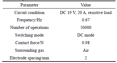
Arc erosion experiment was finished by electrical performance testing machine that was jointly developed by FuDa Alloy Material Co., Ltd. and Xi��an Jiaotong University. The experimental conditions are shown in Table 1.
Mass losses were measured using an electrical scale. By using the scale, mass changes more than 0.1 mg can be measured in accuracy. Microstructure was characterized by an optical microscope (L150), two- dimensional and three-dimensional morphologies were characterized by a scanning electron microscope (JSM-6390A) and a 3D optical profiler (WYKO- NT9100), respectively.
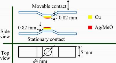
Fig. 1 Shape of contact
Table 1 Experimental conditions
3 Results
3.1Microstructrue and physical performances
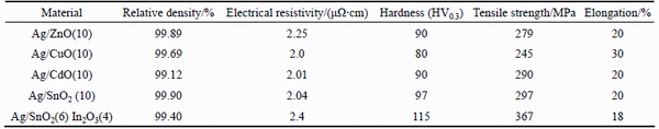
Optical microstructure of Ag/MeO(10) electrical contact materials was represented in Fig. 2, where oxide particles were uniformly distributed on silver matrix. Particle size of ZnO and CuO was smaller than that of CdO, SnO2 and SnO2In2O3. Physical performances of Ag/MeO(10) electrical contact materials were represented in Table 2, where physical performances (relative density, electrical resistivity, hardness, tensile strength and elongation) of Ag/MeO(10) were different due to the difference of alloy components. Relative density of Ag/SnO2(10) electrical contact material was the largest and that of Ag/CdO(10) electrical contact material was the smallest. Electrical resistivity, hardness and tensile strength of Ag/SnO2(6)In2O3(4) electrical contact material were the largest and those of Ag/CuO(10) electrical contact material were the smallest. Whereas elongation of Ag/CuO(10) electrical contact material was the largest and that of Ag/SnO2(6)In2O3(4) electrical contact material was the smallest. Ag/MeO electrical contact material belongs to metal matrix composites with particle reinforce, whose hardness and tensile strengthen were dependent on reinforce phase (oxide particle) size and dispersion strengthening effect. Small particle size and excellent dispersion strengthening effect will result in the increase of hardness and tensile strength. At the same time, both oxide particle size and dispersion strengthening effect were the main influence factors of electrical conductivity of Ag/MeO electrical contact materials. Electron must pass through more oxide particles under the metal matrix composites with small particle size and good excellent dispersion strengthening effect, which resulted in the electrical resistivity increasing due to the required energy increasing. In addition, electrical conductivity and hardness of oxide particle also had an important influence on electrical conductivity, hardness, tensile strength and elongation of Ag/MeO electrical contact materials. Densification degree of powders mainly depended on extrusion and drawing process. Densification process of powders was actually exhaust process. Dispersion distribution of oxide particles can supply more exhaust passage, which will result in higher relative density of Ag/MeO electrical contact materials.
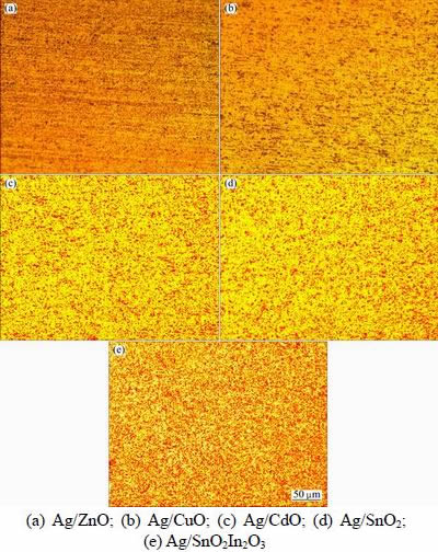
Fig. 2 Optical microstructures of Ag/MeO(10) electrical contact materials
Table 2 Physical performance of Ag/MeO electrical contact materials
3.2 Mass change after arc erosion
Mass of movable and stationary contact will change under the action of arc erosion due to evaporation and splash erosion. In addition, material transfer occurring between movable and stationary contact during arc operation will also result in their mass change. Mass change to some extent reflected the degree of arc erosion. Mass change of Ag/MeO(10) electrical contact materials after 50000 operations was represented in Fig. 3. Mass change on cathode was different from that on the anode. Masses of Ag/CuO(10) and Ag/CdO(10) contact materials on cathode were increased, while masses of other Ag/MeO(10) contact materials were all decreased after arc erosion. Mass change of Ag/SnO2(6)In2O3(4) on cathode was the smallest (-0.4 mg), while that of Ag/ZnO(10) on anode was the smallest (-0.3 mg). Mass change of Ag/SnO2(10) on cathode was the largest (-1.5 mg), while that of Ag/CuO(10) on anode was the largest (-3.7 mg).
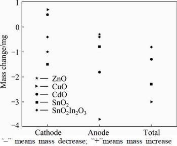
Fig. 3 Mass change of Ag/MeO(10) electrical contact materials after arc erosion
3.3 Arc erosion morphology
3.3.1 Two-dimensional macro-morphology
The two-dimensional macro-morphologies of Ag/MeO(10) electrical contact materials containing different alloy components (ZnO, CuO, CdO, SnO2 and SnO2In2O3) after 50000 operations were represented in Fig. 4. Surface morphology of Ag/MeO(10) contact material was changed under arc erosion action. Arc erosion spots were observed on both cathode contact and anode contact surface. For the same Ag/MeO(10) contact material, arc erosion morphology of cathode contact was different from that of anode contact. For the same electrode, arc erosion morphologies of Ag/MeO(10) electrical contact material containing different alloy components (ZnO, CuO, CdO, SnO2 and SnO2In2O3) were different, which indicated that alloy component had an important influence on arc erosion morphology of Ag/MeO electrical contact materials. Circle erosion spot was observed on both cathode and anode contact surface of Ag/ZnO(10) contact material, and erosion spot on both cathode and anode contact was relatively flat. Several large convex peaks were observed on Ag/CuO(10) and Ag/CdO(10) cathode contact surface, while several large concave pits were observed on Ag/CuO(10) and Ag/CdO(10) anode contact surface. Many small convex peaks were observed on Ag/SnO2(10) and Ag/SnO2(6)In2O3(4) cathode contact surface, while many small concave pits were observed on Ag/SnO2(10) and Ag/SnO2(6)In2O3(4) anode contact surface. The result of Fig. 4 indicated that surface change of Ag/CuO(10) and Ag/CdO(10) contact materials was the most serious and that of Ag/SnO2(10) contact material was the slightest. Consequently, arc erosion of Ag/CuO(10) and Ag/CdO(10) contact materials was the most serious and that of Ag/SnO2(10) contact material was the slightest. Arc erosion resistance of Ag/SnO2(10) contact material was better than that of other Ag/MeO(10) contact material in this experiment.
3.3.2 Three-dimensional macro-morphology
Three-dimensional macro-morphologies of Ag/MeO(10) electrical contact materials containing different alloy components (ZnO, CuO, CdO, SnO2 and SnO2In2O3) after 50000 operations were represented in Fig. 5.
Three-dimensional morphology of Ag/MeO(10) electrical contact materials clearly reflected the change details of surface after arc erosion, which was very helpful to analyze the influence of arc erosion on Ag/MeO(10) electrical contact materials. Contact area of Ag/ZnO(10) between cathode and anode was larger and surface change was smaller. Deformation was observed on Ag/ZnO(10) anode surface due to the action of contact force and arc erosion. Surface morphology of Ag/CuO(10) and Ag/CdO(10) was seriously changed after arc erosion. Cathode surface of Ag/CuO(10) and Ag/CdO(10) was changed from curved shape to peak shape. Anode surface of Ag/CuO(10) and Ag/CdO(10) was changed from curved shape to crater shape. Four large peaks were observed on Ag/CuO(10) cathode contact surface, while four corresponding pits were observed on anode contact surface. Five small peaks were observed on Ag/CdO(10) cathode contact surface, while corresponding five pits were observed on anode contact surface. Arc erosion of Ag/CuO(10) and Ag/CdO(10) contact material belongs to point contact, which means that arc mainly gathered in several contact points and then resulted in serious arc erosion. Surface morphology change of Ag/SnO2(10) contact material was the same as Ag/ZnO(10) contact material. But the contact area of Ag/SnO2(10) between cathode and anode was larger than that of Ag/ZnO(10), and surface change and deformation were slighter than those of Ag/ZnO(10). So, the arc erosion of Ag/SnO2(10) contact material was slighter than that of Ag/ZnO(10). Several very small peaks were observed on Ag/SnO2(6)In2O3(4) cathode surface and several corresponding small pits were observed on anode surface. At the same time, contact zone was observed between cathode and anode surface. So, arc erosion of Ag/SnO2(6)In2O3(4) contact material included not only point contact but also area contact. Consequently, arc erosion resistance of Ag/SnO2(10) contact material was the best and that of Ag/CuO(10) contact material was the worst.
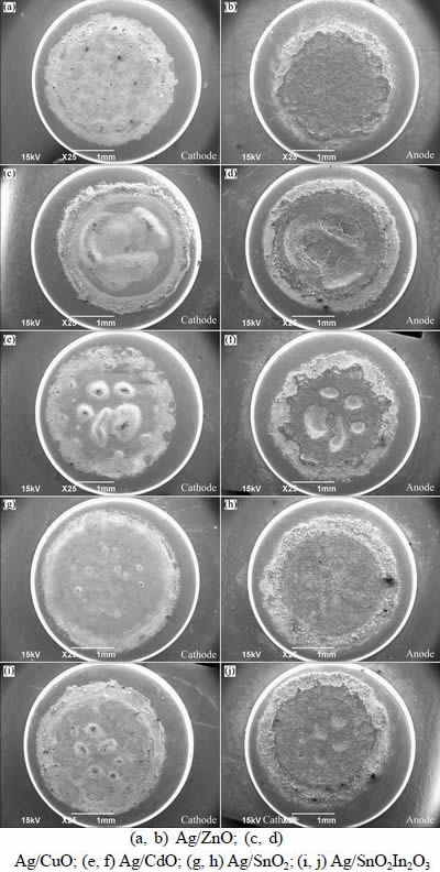
Fig. 4 Two-dimensional macro-morphologies of Ag/MeO(10) electrical contact materials after arc erosion
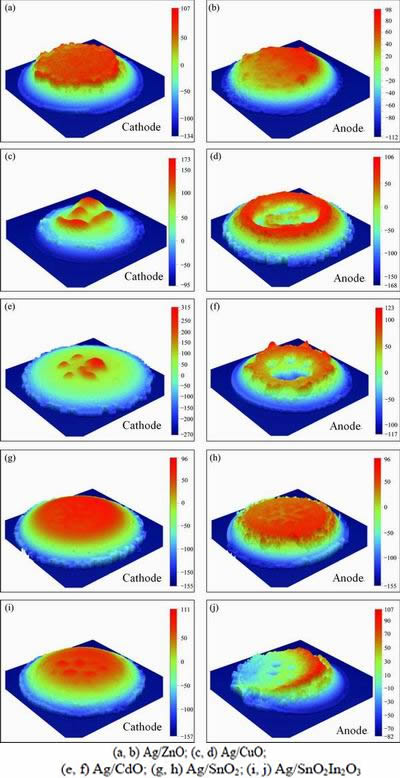
Fig. 5 Three-dimensional morphologies of Ag/MeO(10) electrical contact materials after arc erosion
3.3.3 Information on contact surface profiles
Information on contact surface X and Y profiles of Ag/MeO(10) electrical contact materials after 50000 operations on center point was represented in Fig. 6 and Fig. 7, respectively. The change of X profile was smaller than that of Y profile on cathode surface of Ag/ZnO(10) electrical contact material. The change of X profile and Y profile was small and similar on anode surface of Ag/ZnO(10) electrical contact material. The results of contact surface profiles indicated that the arc erosion on cathode of Ag/ZnO(10) electrical contact material was more serious, which was consistent with the result of mass change. Peaks were observed on cathode surface profile, craters were observed on anode surface profile of Ag/CuO(10) and Ag/CdO(10) contact materials. It indicated that arc erosion resulted in the material transfer from anode to cathode of Ag/CuO(10) and Ag/CdO(10) contact materials. At the same time, it also explained the reason of Ag/CuO(10) and Ag/CdO(10) contact materials mass increasing on cathode. The change of X profile and Y profile was slight and similar on cathode surface, while the change of X profile was larger than that of Y profile on anode surface of Ag/SnO2(10) electrical contact material. The change of X profile and Y profile was slight, but a small peak was observed on cathode surface profile of Ag/SnO2(6)In2O3(4) contact material. While the change of X profile and Y profile was large on anode surface of Ag/SnO2(6)In2O3(4) contact material. It indicated that the arc erosion on anode was more serious than that on cathode of Ag/SnO2(6)In2O3(4) contact material.
4 Discussion
Arc erosion of electrical contact material was a kind of very complicated physical phenomena. Influence factors of arc erosion mainly included electrical factors (voltage, current and load), material factors (physical and chemical properties, fabrication method and additive), mechanical factors (contact shape and size, electrode spacing and arc movement) and environmental factors (temperature, humidity, environmental media and pressure). In this work, the influence of material factor (alloy components) on arc erosion of Ag/MeO(10) was investigated. The above results indicated that alloy components had an important influence for microstructure, physical performance, mass change of arc erosion and arc erosion morphology of Ag/MeO(10) contact materials. So, it was desirable to discuss the influence of alloy components on arc erosion process and mechanism of Ag/MeO(10) electrical contact materials.
Opening or breaking a contact pair in a low voltage switching system usually results in an arc being drawn between the contact pair. In the opening process, gas between electrode spacing became conductor from insulators due to the gas ionization and then resulted in the arc discharge. Arc discharge made the temperature rising and then led to arc erosion. At the same time, the collision between moveable and stationary contact will cause mechanical wear and bounce, which results in the arc time extending. In the breaking process, contact resistance increased due to the decrease of contact force and actual conducting area. At the instant of contact surface separation, the heat generated by electrical contact resistance will be concentrated to a very small range area and then make temperature rise quickly to metal melting point and boiling point. Finally, it may cause the explosive vaporization. Whether in opening or breaking process, arc will be generated between electrodes. Arc will repeatedly erode the contact surface and then result in the change of contact surface composition and morphology and temperature rising. The changes of contact surface composition mainly include floating, sinking and enrichment of the second phase particles with high melt point in the arc molten pool, enrichment of the matrix component, and surface contamination. Changes of surface morphology mainly include the melting, splash, liquid flow, evaporation and solidification of material.
The above results indicated that alloy component had an important influence on the arc erosion of Ag/MeO(10) electrical contact materials. Arc erosion morphology of Ag/ZnO(10) and Ag/SnO2(10) electrical contact materials was similar, and that of Ag/CuO(10) and Ag/CdO(10) electrical contact materials was similar.
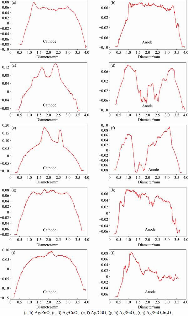
Fig. 6 Information on contact surface X profiles of Ag/MeO electrical contact materials at center point
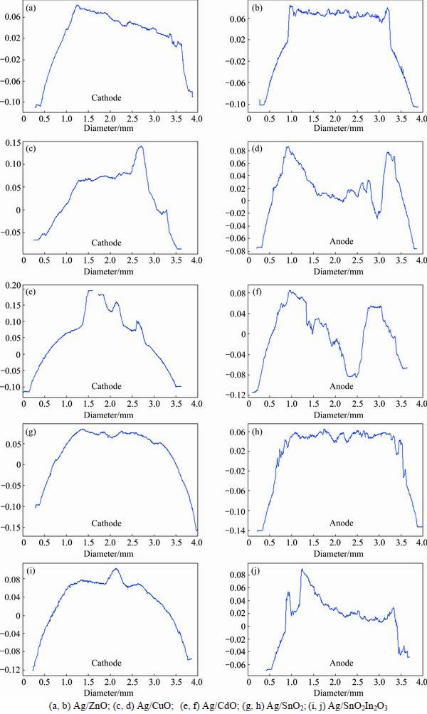
Fig. 7 Information on contact surface Y profiles of Ag/MeO electrical contact materials at center point
Arc erosion of Ag/ZnO(10) and Ag/SnO2(10) electrical contact materials was mainly liquid splash and evaporation, and that of Ag/CuO(10) and Ag/CdO(10) electrical contact materials was mainly material transfer from anode to cathode. Arc erosion of Ag/SnO2(6)- In2O3(4) electrical contact materials included both liquid splash, evaporation and material transfer. Arc erosion process schematic diagram of Ag/MeO(10) electrical contact materials in breaking process was represented in Fig. 8. When contact material moved from connect to disconnect position, contact force and actual conducting area necessarily gradually decreased, which resulted in the contact resistance increasing and contact surface temperature rising. So, when the contact materials began to break, contact surface melted and formed molten metal bridge between cathode and anode due to the contact resistance increasing and contact surface temperature rising. With the increase of spacing between cathode and anode, the metallic phase arc generated and discharged since the metal vapor between electrode spacing freed from the contact surface. Charged particles were mainly electron, metal ion and metal atoms. Metal ion and electron moved to cathode and anode surface under the action of electric field force, respectively. The metal ion deposited on cathode surface and formed peak, while the electron bombarded the anode and then resulted in the further rising on anode surface. So, the material transferred from anode to cathode (see Fig. 9), which can lead to the change of electrode spacing and cause the ration change between connect and break and finally lead to the failure of contact.
5 Conclusions
1) More detailed information of arc erosion morphology can be obtained by using 3D optical profiler, since it not only can characterize three-dimensional morphology but also can truly characterize the arc erosion surface profile of electrical contact materials, which is helpful to analyze arc erosion mechanism of electrical contact materials.
2) Arc erosion morphology of Ag/MeO(10) electrical contact materials after 50000 operations under direct current of 19 V and 20 A and resistive load conditions mainly includes three types. Arc erosion morphology of Ag/ZnO(10) and Ag/SnO2(10) electrical contact materials was mainly liquid splash and evaporation, and that of Ag/CuO(10) and Ag/CdO(10) electrical contact materials was mainly material transfer from anode to cathode. Arc erosion morphology of Ag/SnO2(6)In2O3(4) electrical contact materials included liquid splash, evaporation and material transfer.

Fig. 8 Arc erosion process schematic diagram of Ag/MeO(10) electrical contact materials in breaking process
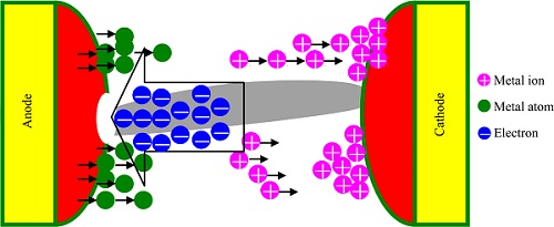
Fig. 9 Schematic diagram of material transfer from anode to cathode
3) In this experimental conditions, the arc erosion resistance of Ag/SnO2(10) electrical contact material was the best and that of Ag/CuO(10) electrical contact material was the worst.
References
[1] JIANG Yong, XU Can-hui, LAN Guo-qiang. First-principles thermodynamics of metal-oxide surface and interfaces: A case study review [J]. Transactions of Nonferrous Metals Society of China, 2013, 23(1): 180-192.
[2] WALCZUK E, BORKOWSKI P, FRYDMAN K, WOJCIK G D, BUNCHOLC W. Migration of composite contact materials components at high current arcing [C]//Proceedings of the International Conference of Electrical Contacts. Sendai, Japan, 2006: 143-149.
[3] CHAABANE L, SASSI M. Experimental determination of factors influencing contact by electrical arc [C]//Proceedings of the International Conference of Electrical Contacts. Saint Malo, France, 2008: 43-47.
[4] JEMAA N B, QUEFFELEC J L. Some investigations on slow and fast arc voltage fluctuations for contact materials proceeding in various gases and direct current [J]. IEEE Transactions on Components, Hybrids, and Manufacturing Technology, 1991, 14: 113-117.
[5] JEMAA N B. Break arc duration and contact erosion in automotive application [J]. IEEE Transaction on Components, Packaging and Manufacturing Technology-Part A, 1996, 1: 82-86.
[6] SCHULLMAN M B, SLADE F G, LOUD LD. Influence of contact geometry and current on effective erosion of Cu-Cr, Ag-WC, and Ag-Cr vacuum contact materials [J]. IEEE Transactions on Components and Packaging Technology, 1999, 3: 405-413.
[7] MCBRIDE J W, SHARKH S M A. The effect of contact opening velocity and the moment of contact opening on the eroding of Ag/CdO contact [C]//Proceedings of the 39th IEEE Holm Conference on Electrical Contacts. Pittsburgh, PA, USA, 1993: 87-95.
[8] CHEN L C, LI Z B, ZOU J Y. Effect of fabrication method and additive on operating performance of silver metal oxide electrical contact materials [J]. Low Voltage Apparatus, 1994, 3: 47-51.
[9] JIA Q C,YU J, CHEN J C, LIU L J, LU W T. Sulfide corrosion behavior, mechanical and optical properties of silver-indium alloy with yttrium addition [J]. Materials Review, 2015, 29(10): 94-96.
[10] VINARICKY E, BEHRENS V. Switching behavior of silver/graphite contact material in different atmospheres in regard to contact erosion [C]//Proceedings of the 44th IEEE Holm Conference on Electrical Contacts. Arlington, VA, USA, 1998: 292-300.
[11] KOSSOWSKY R, SLADE PG. Effect of arcing on the microstructure and morphology of Ag/CdO contacts [J]. IEEE Transactions on Parts, Hybrids, and Packing, 1973, 9: 39-44.
[12] WITTER G J, POLEVOY I. A study of contact resistance as a function of electrical load for silver based contacts [C]//Proceedings of the International Conference of Electrical Contacts. Nagoya, Japan, 1994: 503-568.
[13] LI J, HOU Y B, LI H, CAI Y, CHEN G M, LI Y L. Study on DC arc erosion of Ag/SnO2 contact material with processing technology and additives [J]. Journal of Hunan Colleges of Engineering, 2012, 22: 1-6.
[14] MAKOTO H, KEISUKE T. Non-contacting evaluation schemes of contact surface damages with several optical techniques [C]//Proceedings of the 1st International Conference on Electric Power Equipment-Switching Technology. Xi��an, China, 2011: 152-155.
[15] SWINGLER J, SUMPTION A. Arc erosion of Ag/SnO2 electrical contacts at different stages of a break operation [J]. Rare Metals, 2010, 29: 87-97.
�Ͻ�Ԫ�ض�Ag/MeO��Ӵ����ϵ绡��ʴ��ò��Ӱ��
�ⴺƼ1,2,3������2���� Φ3�����ػ�3��������1
1. ���ϴ�ѧ ��Դ��ѧ�빤��ѧԺ����ɳ 410083��
2. ���ϴ�ѧ ���Ͽ�ѧ�빤��ѧԺ����ɫ�������Ͽ�ѧ�빤�̽������ص�ʵ���ң���ɳ 410083;
3. ����Ͻ���Ϲɷ�����˾������ 325025
ժ Ҫ��ͨ��ɨ��羵����ά��ѧ�����ǹ۲�Ag/MeO(10)��ͷ��ֱ��19 V��20 A�������غ������²���50000�κ�ĵ绡��ʴ��ò�������������ά��ѧ�����ǿ����ṩ����������ϸ�ı�����ʴ��ò��Ϣ������ͬ�IJ��������£�Ag/SnO2(10)��ͷ�Ŀ��绡��ʴ������ǿ����Ag/CuO(10)��ͷ�Ŀ��绡��ʴ������Ag/MeO(10)��ͷ�ĵ绡��ʴ��ò��Ҫ���������͡�Ag/ZnO(10) ��Ag/SnO2(10)�ĵ绡��ʴ��ò��Ҫ��Һ���罦��������Ag/CuO(10)��Ag/CdO(10)��ͷ�ĵ绡��ʴ��ò��Ҫ�Dz��ϴ�������������ת�ƣ���Ag/SnO2(6)In2O3(4)��ͷ�ĵ绡��ʴ��ò�����Һ���罦���������в��ϵ�ת�ơ����⣬���۲�ͬAg/MeO(10)��ͷ�ĵ绡��ò���γɹ��̺ͻ�����
�ؼ��ʣ�Ag/MeO��ͷ���Ͻ���Ԫ���绡��ʴ��ò����ά��ѧ������
(Edited by Yun-bin HE)
Foundation item: Project (2012QNZT003) supported by the Fundamental Research Funds for the Central Universities, China; Project (2012M521542) supported by the Postdoctoral Science Foundation of China; Project (14JJ3014) supported by the Hunan Provincial Natural Science Foundation of China; Project (BSh1202) supported by the Zhejiang Provincial Postdoctoral Scientific Research Foundation of China
Corresponding author: Chun-ping WU; Tel: +86-731-88877862; E-mail: wcpphd@126.com
DOI: 10.1016/S1003-6326(16)64105-5
Abstract: Arc erosion morphologies of Ag/MeO(10) electrical contact materials after 50000 operations under direct current of 19 V and 20 A and resistive load conditions were investigated using scanning electron microscope (SEM) and a 3D optical profiler (3DOP). The results indicated that 3DOP could supply clearer and more detailed arc erosion morphology information. Arc erosion resistance of Ag/SnO2(10) electrical contact material was the best and that of Ag/CuO(10) was the worst. Arc erosion morphology of Ag/MeO(10) electrical contact materials mainly included three different types. Arc erosion morphologies of Ag/ZnO(10) and Ag/SnO2(10) electrical contact materials were mainly liquid splash and evaporation, and those of Ag/CuO(10) and Ag/CdO(10) were mainly material transfer from anode to cathode. Arc erosion morphology of Ag/SnO2(6)In2O3(4) electrical contact materials included both liquid splash, evaporation and material transfer. In addition, the formation process and mechanism on arc erosion morphology of Ag/MeO(10) electrical contact materials were discussed.
