

Structural stability estimation of whirling unit
Son-Jae HWAN1, Han-Chang WOO2, Lee-Sang RYONG3, Lee-Young MOON3
1. Daegu Machinery Institute of Component & Materials Foundation, Daegu, Korea;
2. Department of Automobile, Yeungnam College of Science & Technology, Daegu, 705-717, Korea;
3. Department of Mechanical Engineering, Kyungpook National University, Daegu, 220-60, Korea
Received 2 March 2009; accepted 30 May 2009
Abstract:
Whirling is a cutting process in which a series of cutting edges on whirling ring remove material by turning over a rotating workpiece. In this study static and dynamic stability of whirling unit was estimated by using ADAMS and NASTRAN softwares. Each maximum force acting on the bearing attached to the spindle assembly and the cutting tool attached to the whirling ring with the rotating speed of 6 000 r/min was 235 N and 902 N respectively. The maximum stress of 0.74 MPa on the base frame is far smaller than the yield strength of 282 MPa. The calculated natural frequency of 148 Hz of the system is far from the frequency of the driving speed of 6 000 r/min. The experimentally obtained maximum cutting force of 792 N is smaller than that of calculated value. And the experimentally obtained natural frequency of 118 Hz is beyond the driving speed of 6 000 r/min. From above results it can be judged that the whirling system is statically and dynamically stable.
Key words:
Whirling unit; structural stability estimation; ADAMS software; NASTRAN software; mode shape measurement;
1 Introduction
Manufacturing of worm gears is very important in the automobile industries. Recently, whirling processes are overwhelmingly used in the manufacture of worms compared to roll forming processes, because of increasing demands of shape accuracy and good surface finish [1]. To achieve a good cutting practice of worm, the structural stability of whirling unit should be analyzed beforehand [2].
In this study, using ADAMS and NASTRAN softwares the structural stability of whirling unit was estimated. At the same time, the cutting force measuring experiments and vibration tests were carried out to substantiate the simulated results.
2 Cutting in whirling unit
Cutting in the whirling unit is performed in which a series of cutting edges around the whirling ring remove material by turning over the rotating workpiece, as shown in Fig.1.
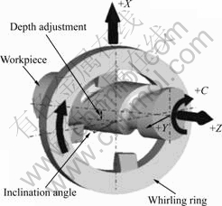
Fig.1 Schematic view of whirling process
The cutting geometry in the whirling unit is shown in Fig.2. The maximum depth of cut, shown in the figure as ��EF��, is calculated from Eq.(1) [3] and the cross section of the chip removed by a cutting insert is shown in the figure as ��CDE�� [4-6].
![]() (1)
(1)
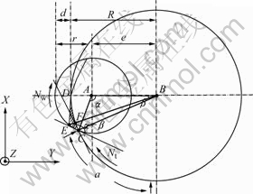
Fig.2 Geometry of cutting in whirling process
3 Cutting force simulation
For simulating the cutting forces in whirling process using ADAMS software, the whirling unit is divided into two parts, i.e. cutting edges and spindle assembly. The 1st, 3 rd, and 5th cutting edges are rough cutting bites and the 2nd, 4th, and 6th are fine cutting bites. The cutting conditions used are shown in Table 1.
Table 1 Cutting input conditions
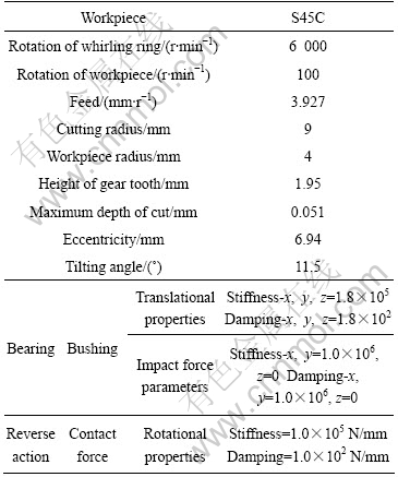
Fig.3 shows that the magnitudes of the estimated cutting forces by rough cutting bites are larger than those by fine cutting bites.
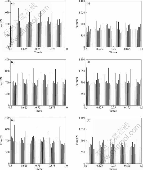
Fig.3 Cutting force of each bite in whirling ring: (a) 1st bite; (b) 2nd bite; (c) 3rd bite; (d) 4th bite; (e) 5th bite; (f) 6th bite
It is observed that the maximum cutting force on the cutting edge is 902 N and the maximum force in the bearing assembly is 235 N. It was known that the magnitude of main cutting force FX is larger than that of the other component forces FY and FZ, as seen in Fig.4 [7-8].
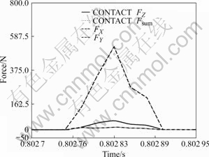
Fig.4 Cutting forces FX, FY, FZ and their sum Fsum
4 Estimation of structural stability
4.1 Maximum stress and deformation
For static structural estimation of the whirling unit using NASTRAN software, the maximum stress and deformation in the unit were obtained.
It is assumed that nodes in the bottom of gear housing have three degree of freedom, and nodes in the center and inner parts of the bearing assembly are constrained in the MPC (Multi Point Constraint) condition, as shown in Fig.5.

Fig.5 Boundary and load conditions of whirling unit
The input force in the center of bearing assembly is 235 N which were obtained using ADAMS software. The mechanical properties of the unit are shown in Table 2.
Table 2 Mechanical properties of unit
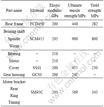
Fig.6 shows that the maximum stress of 0.74 MPa on the base frame and the maximum deformation at the end of the motor is 1.75 ��m [9]. The yield strength of the base frame is 282 MPa and the deformations in the whirling unit are negligible. From the above it can be judged that the structure of the whirling unit is statically stable [10].
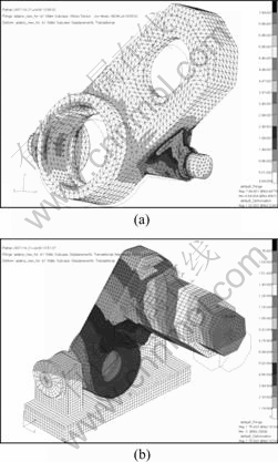
Fig.6 Von-Mises stress of base frame (a); Deformation of motor in whirling unit (b)
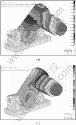
Fig.7 1st (a) and 2nd (b) order mode shape
4.2 Natural frequencies
For dynamic structural stability estimation of whirling unit, the modal analysis of the vibration with NASTRAN software was carried out.
At the 1st order mode it was found that the displacement of the motor and the whirling body are the largest in the whirling unit, their natural frequency is 148 Hz. At the 2nd order mode it was known that the displacement of the motor is the largest and its natural frequency is 258 Hz.
The driving speed of 6 000 r/min of whirling unit is far below the estimated natural frequencies of 148 Hz (8 800 r/min) and 258 Hz (15 400 r/min) respectively. It can be judged that the structure of whirling unit is dynamically stable.
5 Experiments for determination of cutting force
The non-contact rotating tool dynamometer (Kistler RCD 9123B) was used to measure the cutting forces generated during the whirling process, as shown in Fig.8.
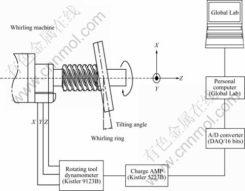
Fig.8 Cutting force measurement system with rotating tool dynamometer
The data of the cutting force components FX, FY, and FZ were obtained at the interval of 40 ��s during the period of 3.4. The sum of cutting force components, Fsum could be calculated from [11]
![]() (2)
(2)
The maximum cutting force on the cutting edge measured in the experiments is 792 N, which is near to the maximum cutting force of 902 N simulated using ADAMS software. The magnitudes of the main cutting force FX and the passive cutting force FY are larger than that of the feed force FZ, as shown in the figure. Because the magnitude of the real passive cutting force FY in the experimental is far larger than that of estimated, the transverse vibration (vibration perpendicular to the axis) of the workpiece takes place[12].
6 Experiments for determination of natural frequency
To measure the natural frequencies of the whirling unit itself, modal test in the stop mode was performed. And to verify whether the resonance takes place at the natural frequencies in the constant speed driving mod
vibration test with no load at specific rotation speed from 4 000 to 8 000 r/min was performed [13]. Fig.10 shows the natural frequencies measurement system. The test conditions are shown in Table 3.

Fig.9 Cutting force components FX, FY, and FZ (a) and their sum Fsum of cutting force (b)
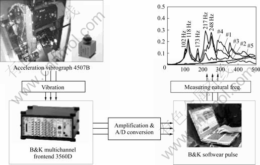
Fig.10 Vibration measurement system with accelerometers
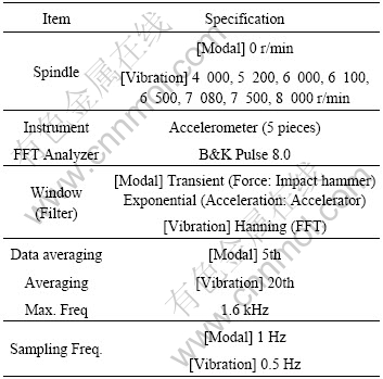
Table 3 Test conditions in modal and vibration test
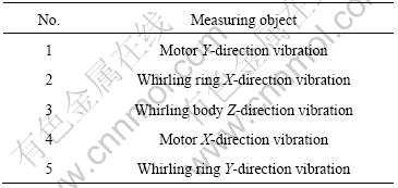
Accelerometers were set-up at the 5 point as shown in Fig.11, and in Table 4 measuring objects are indicated. Fig.12 shows that several parts of whirling unit vibrate at their natural frequencies between 100 and 270 Hz. But the responses of the 2 and 5 accelerometers in the figure shows that the whirling ring does not vibrate below 500 Hz. On the other hand the responses of No.1, No.3, and No.4 accelerometers show that the motor and whirling body vibrate at the natural frequencies of 118, 173, 217, and 248 Hz.
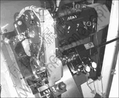
Fig.11 Setting-up positions of accelerometers
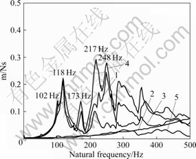
Fig.12 Measurement results of natural frequency in modal test
Table 4 Vibration measuring objects with accelerometers
The result of 1st order vibration test in the constant speed driving mode shows the larger displacement of the vibration takes place at 118 Hz (7 080 r/min) than any other frequencies, as shown in Fig.13. The reason is that the frequency of the forced vibration is the same with the natural frequency of the free vibration.

Fig.13 Test result of vibration at 1st order mode
And it was verified that the natural frequency of 118 Hz of the motor and whirling body measured in the test was near to that of 148 Hz at the 1st order mode estimated using NASTRAN software.
Fig.14 shows the result of the 2nd order vibration test in the constant speed driving mode. It can be found that the resonance did not take place at 173, 217 and 248 Hz, which were the natural frequencies of the free vibration measured in the modal test [14].
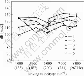
Fig.14 Test result of vibration at 2nd order mode
7 Conclusions
1) With the non-contact rotating tool dynamometer, it was verified that the cutting force of 920 N estimated is effective.
2) The maximum estimated stress and deformation of the whirling unit were 0.74 MPa and 1.75 ��m. It can be judged that the structure of the whirling unit is statically stable.
3) The natural frequency of the motor and whirling body measured in the vibration test was 118 Hz, which was near to that of estimated 158 Hz.
4) The natural frequency of 118 Hz (7 080 r/min) measured in the vibration test was beyond the driving speed of 6 000 r/min of the whirling unit, and it can be judged that the structure of the whirling unit was dynamically stable.
References
[1] KO D C, LEE J M, KIM B M. Development of form rolling technology for high precision worm using the rack dies of counter flow type [J]. Journal of the Korean Soc Precision Eng, 2004, 21: 57-64.
[2] LEE J K, YANG W C, SON J S, HAN H D, KIM H S. A study on performance improvement of whirling machines [J]. Journal of the Korean Soc Mech Eng, 2005, 29: 1416-1429.
[3] MALKIN S. Grinding technology [M]. Chichester: Ellis Horwood Limited, 1989: 5-116.
[4] SON J H, PARK C W, KIM S I, JUNG H C, HAN C W, LEE Y M. Cutting force analysis in whirling process [C]//International Conference on Advanced Materials, Development and Performance. 2008: 131-137.
[5] SHETH D S, MALKIN S. CAD/CAM for geometry and process analysis of helical groove machining [J]. Annals of CIRP, 1990, 39(1): 129-132.
[6] MOHAN L V, SHUNGMUGAM M S. Simulation of whirling process and tool profiling for machining of worm [J]. Journal of Materials Processing Technology, 2007, 185: 191-197.
[7] LITVIN F L, NAVA A, FAN Q, FUENTES A. New geometry of face worm gear drives with conical and cylindrical worms; generation, simulation of meshing, and stress analysis [J]. Computer Methods in Applied Mechanics and Engineering, 2002, 191: 2035-3054.
[8] SU D, QIN D. Integration of numerical analysis, virtual simulation and finite element analysis for the optimum design of worm gearing [J]. Journal of Materials Processing Technology, 2003, 138: 429-435.
[9] SIMON V. Stress analysis in worm gears with ground concave worm profile [J]. Mechanism and Machine Theory, 1996, 31: 1121-1130.
[10] COCHARAN W G. Approximate Significance level of the behrens-Fisher test [J]. Biometrics, 1964, 20: 191-195.
[11] REGINALD C, GEORGE E C, ALVIN M S. Modelling of friction stir welding for robotic implementation [J]. Int Journal of Modelling, Identification and Control, 2006, 1: 101-106.
[12] KULJANIC E, SORTINO M. TWEN, a method based on cutting forces-monitoring tool wear in face milling [J]. Int Journal of Machine Tools & Manufacture, 2005, 45: 29-34.
[13] RAO S S. Mechanical vibration [M]. Pearson Prentice Hall, 2004: 711-716.
[14] SHIN Y C, EMAN K F, WU S M. Experimental complex modal analysis of machine tool structures [J]. Journal of Engineering for Industry, 1989, 111: 126-131.
Corresponding author: Lee-Young MOON; Tel: +82-53-950-5574; Fax: +82-53-950-6550; E-mail: ymlee@knu.ac.kr
